© Korean Powder Metallurgy Institute 881
-Diamond distribution in a diamond tool is typically random due to the powder metallurgy used to manufacture the tool. During blending process of diamond grits and metal powder, the light diamond is intrinsically difficult to mix uniformly with the heavy metal. Consequently, diamond tend to segregate in the diamond tool. When diamond grits are too close to one another, they do not penetrate into the work material effectively. On the other hand, if diamond grits are too sparse in spacing, they tend to be overly stressed during the cutting action. As a result, diamond tools perform poorly due to the segregation of diamond grits in the tool matrix.
In 1997, Chien-Min Sung applied several patents that showed the first time diamond grits could be set in a predetermined pattern. Since then, this method has been practiced with diamond tools that outperformed conventional products.
Fig. 1. The patents of Chien-Min Sung (Sung, U.S. Patents 6,039,641; 6,193,770; 6,286,498; 6,368,198; 6,679,243; 6,884,155) allow diamond to be distributed with a predetermined pattern.
Fig. 2. DiaGrid® diamond tools introduced in 1997 by
Kinik Company.
Diamond Disks’ Revolutions 2006 POWDER METALLURGY
World Congress
C06-02-2
Diamond Tools with Diamond Grits Set in a Predetermined Pattern
James C. Sung
1
KINIK Company, 64, Chung-San Rd., Ying-Kuo, Taipei Hsien 239, Taiwan, R.O.C.
2
National Taiwan University, Taipei 106, Taiwan, R.O.C.
3
National Taipei University of Technology, Taipei 106, Taiwan, R.O.C. [email protected]
Abstract
In 1997, Dr. James Chien-Min Sung patented the technology of making diamond tools according to a predetermined pattern. The optimization of this pattern may double the tool life and the cutting speed. In 1998, Sung also made DiaGrid® saw
segments that showed superior performance in cutting granite and marble. In 2000, Sung visited Shinhan and introduced them this revolutionary concept of diamond saw segments. In 2005, Shinhan adapted the idea and produced saw segments with diamond grits set in a predetermined pattern, their results confirmed that the sawing speed and the sawing life were both improved over conventional designs.
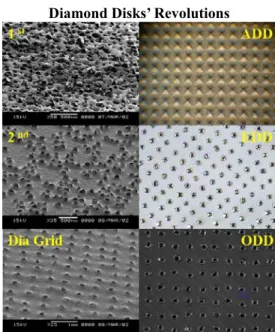
© Korean Powder Metallurgy Institute 882 -Fig. 3. The conversion of randomly distributed diamond for CMP pad conditioners and the new designs of ADD stands for Advanced Diamond Disk for polycrystalline (PCD) pad conditioners. ODD stands for Organic Diamond Disk with diamond set in an epoxy resin. EDD stands for Electroplating Diamond Disks. All ADD, ODD, and EDD are reversely manufactured with diamond tips leveled to within 10 microns. In contrast, conventional diamond disks, even it has a diamond grid pattern, has a very large diamond tip variations (50-100 microns). All samples were designed for fitting Applied Materials Mirra Polisher with diameter about 100 mm.
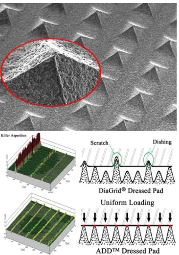
Due to the highly leveled diamond tips, ADD can dress pad to produce a much uniform asperities. Such uniformity can assure the uniform polishing of expensive wafers. In contrast, conventional diamond grid pad conditioners dressed pad show uneven asperities. The highest “killer asperities” can easily cause the ove polishing of interconnects. Such over polishing can result in scratch damages or dishing erosion on the wafer surface.
Fig. 4. Conventional diamond grid may create “killer asperities” on the pad, and hence, the wafer being polished may be damaged. ADD™ will never produce “killer asperities” so they are ideal for making IC with 65 nm line width or smaller.
Fig. 5. Diamond saw segments with diamond distributed in a predetermined pattern (Sung, Chien-Min, Superhard Materials, Chung-Hwa Publication, 2000, Fig. 4-46 for the left diagram; and 2005 Industial Diamond Review for the right diagram).
Fig. 6. An ideal saw segment that shows the gradation of diamond size and diamond concentration. The larger diamond is located at the center for faster cutting. The small diamond flanks on both side to allow a smoother finish on the cut surface. Also the diamond concen- tration is higher toward the leading edge where the severe cutting action is taking place.
References
1. Chien-Min Sung, U.S. Patent 6,039,641. (2000) 2. Chien-Min Sung, U.S. Patent 6,193,770. (2001) 3. Chien-Min Sung, U.S. Patent 6,286,498. (2001) 4. Chien-Min Sung, U.S. Patent 6,368,198. (2002) 5. Chien-Min Sung, U.S. Patent 6,679,243. (2004) 6. Chien-Min Sung, U.S. Patent 6,884,155. (2005)