Calculations of IAEA-CRP-6 Benchmark Case 1 through 7 for a TRISO-Coated Fuel Particle
Kim Young Min, Y.W. Lee, and J.H. ChangKorea Atomic Energy Research Institute
P.O. Box 105, Yuseong-gu, Daejeon, 305-600, Republic of Korea E-mail: [email protected]
1. Introduction
IAEA-CRP-6 is a coordinated research program of IAEA on Advances in HTGR fuel technology. The CRP examines aspects of HTGR fuel technology, ranging from design and fabrication to characterization, irradiation testing, performance modeling, as well as licensing and quality control issues.
The benchmark section of the program treats simple analytical cases, pyrocarbon layer behavior, single TRISO-coated fuel particle behavior, and benchmark calculations of some irradiation experiments performed and planned. There are totally seventeen benchmark cases in the program. Member countries are participating in the benchmark calculations of the CRP with their own developed fuel performance analysis computer codes. Korea is also taking part in the benchmark calculations using a fuel performance analysis code, COPA (COated PArticle), which is being developed in Korea Atomic Energy Research Institute.
The study shows the calculational results of IAEA-CRP-6 benchmark cases 1 through 7 which describe the structural behaviors for a single fuel particle.
2. Development of COPA-MECH
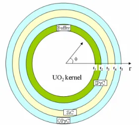
The TRISO-coated fuel particle consists of a kernel, a buffer, an inner pyrocarbon (IPyC) coating layer, a silicon carbide (SiC) barrier layer, and an outer pyrocarbon (OPyC) coating layer as shown in Figure 1. The SiC layer can be assumed to be elastic. The SiC layer is considered to remain unchanged under irradiation and experience no significant change in its mechanical properties during life. Under fast neutron irradiation, the PyC layer first shrinks and then swells in the radial direction, and continually shrinks in the tangential directions. The PyC layer experiences irradiation-induced creep as well.
The mathematical modeling on thermo-mechanical behaviors of a TRISO-coated fuel particle is set up for the three coating layers [1]. The solution can be obtained by a combined method of a closed form solution method [1, 2] and an explicit solution method [3]. Using the solution, a FORTRAN program, COPA-MECH, was developed to calculate the stresses and strains of the three coating layers.
Figure 1. A TRISO-coated fuel particle. 3. Benchmark Case 1 through 7 of IAEA-CRP-6 Case 1 is for elastic SiC. The particle has a kernel, a buffer, and only a SiC coating layer. The SiC coating layer is elastic. Case 2 is for a simple BISO. The particle has a kernel, a buffer, and only an IPyC coating layer. Case 3 is for IPyC and SiC composite without fluence. The particle has a kernel, a buffer, and two coating layers, IPyC and SiC. Case 4a is for IPyC and SiC composite with no creep and constant swelling. Case 4b is for IPyC and SiC composite with constant creep and no swelling. Case 4c is for IPyC and SiC composite with constant creep and constant swelling. Case 4d is for IPyC and SiC composite with constant creep and fluence-dependent swelling. In Case 4, the particle is the same one as in Case 3. Case 5 through 8 are for a TRISO. In Case 5, the particle has a kernel whose diameter is 350 µm. In Case 6, the particle has a kernel whose diameter is 500 µm. In Case 7, the particle is the same as in Case 6 except that the pyrocarbon BAF is increased to 1.06.
Dimensional and material data for Case 1 through 7 are presented in the reference 4.
4. Results
Table 1 shows the maximum tangential stresses of the SiC layer in Case 1 through 3 calculated with the codes COPA-MECH, PARFUME (USA), and STRESS3 (UK). Transactions of the Korean Nuclear Society Autumn Meeting
The results are in good agreement except the PARFUME result in Case 3. Figure 2 presents the radial stress between the IPyC and SiC layers, and the maximum tangential stresses of the IPyC and SiC layers in Case 4d. The results from COPA and PARFUME shows a little disagreement when the fluence is between 0.5×1025 and
0.8×1025 n/m2. Figures 3 through 5 are the maximum
tangential stresses of the IPyC and SiC layers in Case 5 through 7, respectively. The tangential stresses of the IPyC layer from COPA and PARFUME are in good agreement all over the fluence range in Case 5 through 7. However, the tangential stresses of the SiC layer do not agree when the fluence is between 0.5×1025 and 2.6×1025
n/m2. Table 1 shows the disagreement of the SiC
tangential stress from COPA and PARFUME. This disagreement will be easily checked and corrected because it consistently appears at the intermediate fluence. Table 1. Maximum tangential stress (MPa) of SiC the layer
in Case 1 through 3
Case COPA PARFUME STRESS3
1 125.19 125.19 125.3 2 50.20 50.20 50.2 3 104.38 108.58 104.3
Figure 2. Radial and tangential stresses of Case 4d.
Figure 3. Tangential stresses of Case 5.
Figure 4. Tangential stresses of Case 6.
Figure 5. Tangential stresses of Case 7. 4. Conclusion
From the calculations of the IAEA-CRP-6 benchmark Case 1 through 7 for a TRISO-coated fuel particle, the following conclusions are made:
1. In Case 1 through 3, the maximum tangential stresses from COPA, PARFUME, and STRESS3 agreed well except PARFUME result in Case 3.
2. In Case 4d, the stresses from COPA and PARFUME showed a little disagreement at the fluence of 0.5×1025 to
0.8×1025 n/m2.
3. In Case 5 through 7, the tangential stresses of the IPyC layer from COPA and PARFUME are in good agreement all over the fluence range, but the tangential stresses of the SiC layer do not agree consistently at the fluence of 0.5×1025 to 2.6×1025 n/m2.
Acknowledgement
This work has been carried out under the Nuclear Research and Development Program supported by the Ministry of Science and Technology in the Republic of Korea. REFERENCES 0 1 2 3 -400 -300 -200 -100 0 100 200 C O PA IPyC tangential SiC tangential PARFUME 0.0 0.5 1.0 1.5 2.0 2.5 3.0 -50 0 50 100 150 CO PA IPyC tangential IPyC /SiC radial SiC tangential PARFUME 0 1 2 3 -400 -300 -200 -100 0 100 200 C OPA IPyC tangential SiC tangential PARFUME 0 1 2 3 -400 -300 -200 -100 0 100 200 C O PA IPyC tangential SiC tangential PARFUME
[1] Miller, G.K., Int. J. Solids Structures, 32(14), pp. 2077-2093 (1995).
[2] Miller, G.K. and R.G. Bennett, J. Nucl. Mater., 206, pp. 35-49 (1991).
[3] Stevens, D.W., Nucl. Technol, 10, pp. 301-306 (1970). [4] Maki, J.T. and G.K. Miller, “TRISO-Coated Particle Fuel Performance Benchmark Cases,” INL (2005).