1. INTRODUCTION
Astable control system is developed and based on the variable structure system (VSS) theory. Variable structure control (VSC) systems, or sliding mode control (SMC) systems have been desired and dynamics are determined by the control laws which drive the system states to reach and remain on a sliding mode surface. SMC is insensitive to the parameters of the system, time varying parameter fluctuation, and external disturbances [1-2]. Hung et al [3] has reviewed the control strategy for linear and nonlinear systems. However, SMC results may fail to meet the desired performance (for example in the steady-state regime).
Recently, some researchers suggested fuzzy sliding-mode controllers (FSMC) which take the features of both SMC and FLC. The fuzzy logic control (FLC) has been an active research topic in automation and control theory since the work of Mandani, [5], which was based on the fuzzy sets theory of Zadeh, [4]. Fuzzy logic control using linguistic information possesses several advantages such as universal approximation theorem and rule-based algorithm [6]. The problems to be resolved in fuzzy logic control design are the determination of the linguistic state space and definition of the membership functions of the control rules. Palm[7] proposed a sliding-mode fuzzy controller, which many fuzzy rules are required in the control process. Yu et al [8], Established a set of linear models to design the controller but not was easily analysed for high-order systems. Park[9] and Chang et al[10] , developed chattering and enhancing the robustness of the controllers , but it was not be satisfactory for higher order systems which
require a higher dimensional switching surface.
Fuzzy inference systems introduced by Takagi and Sugeno (T-S) [11] change the defuzzification procedure where dynamic systems are used for this purpose. The potential advantage of the method is that, under certain constraints, the stability of the system can be studied. Jang et al [12] propose an adaptive neuro fuzzy inference system (ANFIS), in which polynomials are used in the defuzzification. Adaptive neuro-fuzzy inference systems exhibit both the numeric power of neural networks and verbal power of fuzzy inference systems. With these approaches, the fuzzy rules can be automatically adjusted to achieve satisfactory system response by some dynamic adaptation laws. These control schemes use many fuzzy rules and prior knowledge of the controlled plant are necessary in the design process. These approaches have inspired researchers to develop the adaptive fuzzy sliding-mode control (AFSMC) [13], by using some fuzzy rules and automatically to adjust the fuzzy rules.
This study, a hybrid proposed control strategy, a nonlinear dynamic systems stabilized the control system by applying sliding mode control (SMC). The sliding mode part of the solution is based on “eigenvalue/vector”-type controller [14], and uses a backstepping approach to tracking errors. Particularly, the work presented in Elf et al [15-16], emphasizes that the robustness and stability properties of intelligent control strategies can be studied through the use of SMC theory, can well be used for the purpose of learning. Adaptive neuro-fuzzy inference systems are used inverse learning. This learning structure also contains a trained forward model of the system place in parallel with the stable
Enhanced Variable Structure Control
With Fuzzy Logic System
Veeraphon Charnprecharut*, Kitti Phaitoonwattanakij*, and Somporn Tiacharoen**
Department of Electronics Engineering, Faculty of Engineering King Mongkut's Institute of Technology Ladkrabang, Bangkok 10520, Thailand.
(Tel : +66-09-799-9928, +66-2-; E-mail: [email protected]*) Department of Electronics Engineering, Faculty of Engineering
North Eastern University, Khonkaen 40000, Thailand. (Tel : +66-43-222-959 ext 128 E-mail: [email protected]**)
Abstract: An algorithm for a hybrid controller consists of a sliding mode control part and a fuzzy logic part which are purposely for nonlinear systems. The sliding mode part of the solution is based on “eigenvalue/vector”-type controller is used as the backstepping approach for tracking errors. The fuzzy logic part is a Mamdani fuzzy model. This is designed by applying sliding mode control (SMC) method to the dynamic model. The main objective is to keep the update dynamics in a stable region by used SMC. After that the plant behavior is presented to train procedure of adaptive neuro-fuzzy inference systems (ANFIS). ANFIS architecture is determined and the relevant formulation for the approach is given. Using the error (e) and rate of error (de), occur due to the difference between the desired output value (yd) and the actual output value (y) of the system. A dynamic adaptation law is proposed and proved the particularly chosen form of the adaptation strategy. Subsequently VSC creates a sliding mode in the plant behavior while the parameters of the controller are also in a sliding mode (stable trainer). This study considers the ANFIS structure with first order Sugeno model containing nine rules. Bell shaped membership functions with product inference rule are used at the fuzzification level. Finally the Mamdani fuzzy logic which is depends on adaptive neuro-fuzzy inference systems structure designed. At the transferable stage from ANFIS to Mamdani fuzzy model is adjusted for the membership function of the input value (e, de) and the actual output value (y) of the system could be changed to trapezoidal and triangular functions through tuning the parameters of the membership functions and rules base. These help adjust the contributions of both fuzzy control and variable structure control to the entire control value. The application example, control of a mass-damper system is considered. The simulation has been done using MATLAB. Three cases of the controller will be considered: for backstepping sliding-mode controller, for hybrid controller, and for adaptive backstepping sliding-mode controller. A numerical example is simulated to verify the performances of the proposed control strategy, and the simulation results show that the controller designed is more effective than the adaptive backstepping sliding mode controller.
Keywords: Fuzzy logic control, nonlinear systems, adaptive backstepping sliding mode controller, Mamdani fuzzy logic, adaptive neuro-fuzzy inference systems, Sugeno model
system. The error signal for the training algorithm is the difference between the training signal and the system output. A adaptive neuro-fuzzy inference systems are transferred to a standard fuzzy system to change the structure and reduce the knowledge base. A numerical example is simulated by the hybrid proposed control strategy and adaptive backstepping sliding mode controller. The quality of simulation results shows the effectiveness of the hybrid proposed control strategy with desired tracking accuracy and robustness.
2. MASS DAMP SYSTEM
The model and some additional uncertainty assumption:
)
(
1
0
1
0
1
0
2 1 2 1
t
m
u
m
x
x
m
d
m
k
x
x
d
ú
ú
û
ù
ê
ê
ë
é
+
ú
ú
û
ù
ê
ê
ë
é
+
ú
û
ù
ê
ë
é
ú
ú
ú
û
ù
ê
ê
ê
ë
é
-=
ú
û
ù
ê
ë
é
&
&
(1)For simplicity, let
m
=
1
, assume the parameter uncertainties arek
Î
[
k
min,
k
Max]
,]
,
[
d
mind
Maxd
Î
. With the uniform bounds are0
)
(
d
d
t
£
,x
1Î
[
x
1min,
x
1Max]
{ }
m
and{ }
m
s
x
x
x
2Î
[
2min,
2Max]
. Let]
,
[
min0
k
k
Maxk
Î
andd
0Î
[
d
min,
d
Max]
be nominal values. In this study, letx
1d is desired trajectory, andx
~
=
x
-
x
d(
t
)
is the corresponding tracking error.3. THE ALGORITHM
3.1 Sliding Mode Control (Variable Structure Control) Variable Structure Control (VSC) has successfully been applied to a wide variety of systems having uncertainties in the representative system models. The philosophy of the control strategy is simple, being based on two goals. First, the system is forced towards a desired dynamics, second, the system is maintained on that differential geometry. In the literature, the former dynamics is named the reaching mode, while the latter is called the sliding mode. The control strategy borrows its name from the latter dynamic behavior, and is called Sliding Mode Control (SMC).
Therefore, for the applications in which the desired signals are unavailable, the method cannot be used without any modification. In this part, parallel to the philosophy of variable structure controller design procedure, a switching function is defined and described by (2). The symbol e seen in (2) is the discrepancy between the reference state value and observed state value.
e
e
s
=
&
+
l
(2)If one replaces error with s of (2), it is
straightforward to prove that the Lyapunov function in (3) is minimized in time and its time derivative is enforced to have negative values.
2
2
1
s
V
=
(3)For this case, the selection of gain values must be reasonably large for compensating the bounds introduced with the new selection.
3.2 Fuzzy Logic Control
The concept of FLC is to utilize the qualitative knowledge of a system to design a practical controller, it is generally applicable to plants that are ill-modeled, but qualitative knowledge of experienced operators available for design. In general, a fuzzy control algorithm consists of a set of heuristic decision rules and can be regarded as a nonmathematical control algorithm, in contrast to a conventional feedback control algorithm. The input signals are first fuzzified to allow a structured fuzzy representation of the input signals. These fuzzy signals are then fed into an fuzzy inference engine which can be a loop-up table or a series of IF-THEN statements. Such a nonmathematical control algorithm has been proved to be very attractive whenever controlled system cannot be well defined or modeled. The fuzzy rules are given in the following form:
i i 1 i 1 i i iis X and x is X THENu isU x IF : i Rule + + (4)
where i=1, 2,… n, Xi and Xi+1 are the label of the fuzzy set (membership functions) of xi and xi+1, and Ui is fuzzy quantity of the controller output. The triangular-typed functions and other typed are used to design the membership functions of IF-part and THEN-part.The complete rule base of a conventional fuzzy system with n input variables has pn rules, where p is the number of linguistic terms per input variable. As the dimension and complexity of a system increase, the size of the rule base increases exponentially. The engine produces a structured description of the control action which must be further defuzzified to get a nonstructural (traditional numerical) control output to drive the system. The defuzzification of the control output is accomplished by the method of center-of-gravity. where wi is the fring weight of the ith rule.
å
å
= =´
=
m i i m i i i fsw
w
s
u
1 1)
(
a
(5)3.3 ADAPTIVE NEURO FUZZY INFERENCE SYSTEMS (ANFIS)
As is known from the theory of fuzzy systems, different fuzzification and defuzzification strategies with different rule base structures can result in various solutions to a given task. Fuzzifier outputs the firing strengths for each rule. The vector of the firing strengths is normalized and the resulting vector is defuzzified by utilizing the first order Sugeno model, in which a polynomial is used as the defuzzifier. The choice concerning the order of the polynomial and the variables to be used in the defuzzifier are left to the designer. The structure for two inputs and one output is illustrated in (6) and a sample rule is described below for m input one output ANFIS.
1 m i, m m i, 1 i,1 i m i, m i,2 2 i,1 1
q
u
q
u
q
f
THEN
U
is
u
AND
AND
U
is
u
AND
U
is
u
IF
++
+
¼
+
=
¼
(6)In the IF part of this representation, lowercase variables denote the inputs, uppercase variables stand for the fuzzy sets corresponding to the domain of each linguistic label. The ANFIS output is clearly a linear function of the adjustable defuzzifier parameters denoted by qi,j. The system that is considered in this study uses Bell shaped membership functions as described by (7) and the overall
realization is given in (8). ij b ij ij j j ij
a
c
u
u
f
21
1
)
(
-+
=
(7)å
å Õ
Õ
å
= = = = = = = Rules i i ni Rules i Inputs j ij j Inputs j ij j Rules i i fw u u f F # 1 # 1 # 1 # 1 # 1 ) ( ) ( (8)In (8), the vector of firing strengths denoted by w is normalized and the resulting vector is represented by wn. The relevant backpropagated error values for the adjustable ANFIS parameters are given in (9) through (11).
ïî
ï
í
ì
+
=
+
£
£
=
1
ew
1
1
ew
ni ni ,m
j
m
j
u
N
qi j j (9) ij ij j ni i ij cc
u
w
F
f
e
N
2
2
)
(
-
-=
(10) ij ij j ni i ijc
u
w
F
f
e
N
3
)
(
2
)
(
2-=
(11)The error backpropagation based part of the training procedure is evaluated by using the quantities described in (9) through (11).
4. CONTROLLER DESIGN
The main objective is to keep the update dynamics in a stable region by used VSC. The block diagram of a hybrid control system is illustrated in Fig.1.
Fig.1 Block diagram of hybrid control system architecture. The first stage presents the derivation of SMC based on parameter stabilizing law. The second stage, ANFIS architecture is determined and the relevant formulation for the approach is given. Using the error (e) and rate of error (de), occur due to the difference between the desired output value (yd) and the actual output value (y) of the system. A dynamic adaptation law is proposed and proved the particularly chosen form of the adaptation strategy. Subsequently VSC creates a sliding mode in the plant behavior while the parameters of the controller are also in a sliding mode (stable trainer).
At the third stage (adjustment stage), Madani architecture is designed and the relevant formulation for the approach is given. According to ANFIS architecture, membership function of the input value (e,de) and the actual output value (y) of the system could be changed to trapezoidal and triangular functions through tuning the parameters of the membership functions and rules base. These help adjust the contributions of both fuzzy control and variable structure control to the entire control value.
4.1 Sliding Mode Control Design
The first step of sliding-mode control design is to select a sliding surface that models the desired closed-loop performance in state variable space. Then design the control such that the system state trajectories are forced toward the sliding surface and stay on it. By used the ”eigenvalue/vector” -type controller, a backstepping approach. The system in component form: 2 1
x
x
·=
(12a))
(
)
(
0 0 2a
x
u
f
x
t
x
·=
T+
+
+
d
(12b) witha
0T=
[
-
k
0-
d
0]
,x
d
d
k
k
x
f
0(
)
=
[
0-
0-
]
. Letx
1d be the desired trajectories, and define the tracking errors withd
x
x
x
~
1=
1-
1 dx
x
x
~
1 2 1 · ·-=
(13a))
(
)
(
0 0 2a
x
u
f
x
t
x
·=
T+
+
+
d
(13b)Now we will use a backstepping approach to
d
x
x
x
~
1 2 1 · ·-=
.x
2=
j
(
x
~
1)
and choose j to stabilizex
~
1x
2x
1d · ·-=
using any favorite method. Take for instance: d px
x
k
x
~
1)
~
1 1(
=
-
-
&
j
(14)The sliding surface can now be defined as
)
~
(
1 2x
x
z
=
-
j
(15)and the differential equation becomes VSC (Stable Trainer) Mass-Damper System å å FLC (ANFIS) -x +xd
)
(
)
(
)
(
0 1 1 2 0t
x
f
u
x
x
x
k
x
a
z
d d p Td
+
+
+
-+
=
·&
&
&
(16)Let the control be defined as
u
x
x
x
k
x
a
u
d d p T+
-+
-=
1 1 2 0(
)
&
&
&
(17)where u will be defined later. Then we have
)
(
)
(
0x
t
f
u
z
·=
+
+
d
Define the Lyapunov-like function
2
1
1
z
V
=
(18)the derivative becomes:
z
t
x
f
u
z
V
£
+
(
0(
)
+
d
(
)
)
· (19) From above we find the bounds (this time less conservative)0
)
(
d
d
t
£
andf
0(
x
)
£
e
x
wher e is the worst-casenorm of
[
k
0-
k
d
0-
d
]
, i.e.e
£
--
]
[
k
0k
d
0d
"
k ,
d
. Now, take(x)sgn(z)
-u
=
h
(20)where h(x) is a continuous positive function defined as
0
,
(x)
D
e
+
d
0+
h
0h
0>
h
x
. Then we get0
0<
-£
z
V
&
h
(21)Note that we can once again choose to approximate the signum function, like
sgn(x)
sat
z
÷÷
ø
ö
çç
è
æ
@
f
where f is the boundary layer coefficient. The total control law is this time given by:)
sgn(
]
[
)
(
0 0 1 1 2 0z
x
x
x
x
k
x
a
u
d d p Th
d
e
+
-+
-=
&
&
&
(22)where
z
=
k
px
1+
x
2-
k
px
1d-
x
&
1p. Placing poles of inner loop, Choosingl
2=
0
,
l
1=
-
1
,2
0
=
h
and geth
=
1
,
f
(
t
)
£
11
.
2361
and5
)
(
)
(
t
=
t
£
g
d
. this givesh
=
18.2361
.4.2 ANFIS Controller Design
The first step in the controller design is designing the sliding surface as the input variable of fuzzy rules, which usually uses the error (e) and the rate of error (de) as the input variables. This study considers the ANFIS structure with first order Sugeno model containing nine rules. Bell shaped membership functions with product inference rule are used at the fuzzification level.
The results presented concern the tuning of all adjustable parameters of the ANFIS structure during the learning process (100 epoch). The ANFIS membership are depicted in Fig. 2. Fig. 3 that show ANFIS surface, a fluctuation occurs on the error or rate of error, it is dampened out by the use of VSC philosophy in the learning strategy.
Fig.2 The ANFIS Membership are Depicted.
Fig.3 The ANFIS Surface. 4.3 Fuzzy Controller Design
From ANFIS architecture, membership function of the input value (e, de) and the actual output value (y) of the system could be change to the trapezoidal and triangular membership functions, as Fig. 4 and Fig. 5 illustrated. Then tuning the parameters (center position and width) of the membership functions. According to ANFIS rules base, the hybrid controller consists of a sliding mode control part and a fuzzy logic part therefor the output of the fuzzy controller is the control signal increment or decrement. Four linguistic fuzzy sets are applied for the input and output variables. Fuzzy rules are obtained based on the following reasoning:
IF the error of the system is at the higher level, the effect of FLC on the system should be more enhanced than that of VSC in order to drive the system to the sliding mode surface rapidly.
IF the error of the system is at the lower level, the effect of FLC on the system should be more enhanced than that of VSC
in order to reduce the rapid change of the control value and the chattering phenomenon of VSC at the balanced position.
IF the error of the system is at the middle level then rate of error is the main effect of FLC. Which the rate of error of the system is normal then the output of FLC in order to improve the rapidness of the system response and drive the system to the desired position rapidly. With the rate of error of the system is higher level then the output of FLC is not changed.
The max-min method and center of gravity method are adopted for fuzzy inference logic and defuzzification algorithm. After adjustment stage the FLC have a surface in Fig. 6.
Fig.4 The Input Membership are Error and Rate of Error.
Fig.5 The Output Membership of FLC.
Fig.6 Fuzzy Control Surface.
5. SIMULATION
The simulation has been done using MATLAB. Three cases of the controller will be considered: for backstepping sliding-mode controller, for hybrid controller, and for adaptive backstepping sliding-mode controller. Experiments will be made to indicate the quality of the desired trajectory tracking, the desired trajectory is
x
1d(t)
=
2sin(2t)
, and theinitial conditions are
x
0=
[
0
.
9
,
-
8
]
T . Moreover, the true parameters arem
=
1
,k
Î
[
0
.
5
,
1
.
5
]
and]
3
,
1
[
Î
d
, while the nominal values in the sliding mode case are set tok
0=
1
,d
0=
2
, the settings used are{ }
m
x
1Î
[
0
,
1
]
,d
(
t
)
£
5
,x
2Î
[
-
10
,
10
]
{ }
m
s
andu
max=
100
{ }
N
5.1 Backstepping sliding-mode controller
A simulation with the controller parameters kp = 2, kd = 4, poles placed at p = [-1; 0], h0 = 2, and boundary layer coefficient f = 0.1,gives the response.
Fig. 7 The tracking response with the backstepping sliding-mode controller.
Fig. 8 The Control force with the backstepping sliding-mode controller. 5.2 Adaptive backstepping sliding-mode controller
Adaptive backstepping sliding-mode controller, as backstepping sliding-mode controller but adapt the unknown constant bias, d(t) = d. When the parameters k and d in the plant assume that these parameters are known. The objective is now to compare a hybrid controller and Adaptive backstepping sliding-mode controller with the controller parameters kp = 2, kd = 4 and g = 50, and true d(t) = d = 5.
Fig. 9 The Tracking Response with The Adaptive Backstepping Sliding-Mode Controller.
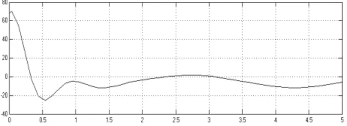
Fig. 10 The Control Force of The Adaptive Backstepping Sliding-Mode Controller. 5.3 The Hybrid Controller
Fig. 11 The Tracking Response with The Hybrid Controller.
Fig. 12 The Control Force of The Hybrid Controller.
Fig. 13 The State Plane of The Adaptive Backstepping Sliding-Mode Controller and Hybrid Controller.
5. CONCLUSION
A new hybrid controller is proposed. Simulations have shown that the hybrid controller performs much better than the adaptive backstepping sliding-mode controller under desired trajectory tracking. The results demonstrate that the hybrid controller has the rapid system response. However, the simulations have shown some responses here to validate the hybrid controller design. Some circumstance, a high frequency of desired trajectory occurs. Therefor the FLC structures should be adjusted again. A further research is still needed. ACKNOWLEDGMENTS
Authors of the paper would like to acknowledge the support of North Eastern University, Khonkaen, Thailand.
REFERENCES
[1] V. I. Utkin, “Variable structure systems with sliding modes,” IEEE Trans. Automatic Control, AC22, No.2, pp. 212-222, 1977.
[2] S. C. Chung and C. L. Lin, “A General Class of Sliding Surface for Sliding Mode 2Control,” IEEE Trans. on Automatic Control, Vol.43, No.1, pp. 115-119, 1998. [3] J. Y. Hung, W. Gao and J. C. Hung, “Variable Structure
Control: A Survey,” IEEE Trans. on Industrial Electronics, v.40, no.1, pp. 2-22, February 1993. [4] L. A. Zadeh, Fuzzy sets, Information and Control, vol. 8,