4-3 / T.-G. Kim
• IMID 2009 DIGEST
Abstract
A red phosphor, (Sr,Ca)2P2O7:Eu2+,Mn2+, for UV-LED
was synthesized under a reducing atmosphere, and its luminescent properties were investigated. The phosphor absorbs ultraviolet light at around 400 nm and efficiently emits red light at approximately 610 nm through an energy transfer from Eu2+ to Mn2+. Using the
varied input current test for the phosphor-loaded LED lamps, it was found that the luminescent efficiency of the phosphor decreased with increasing light flux. This might be due to an increased probability of excited-state absorption and the consequent non-radiative relaxation in Mn2+ ions in the condition of high photon influx.
1. Introduction
Recently, InGaN-based white light emitting diodes (LEDs) have attracted much attention as one of the next generation illumination systems due to their high efficiency, excellent durability, and eco-friendly substances. A common method for fabricating white light LEDs is through combinations of the blue emission from InGaN chips and the yellow light from phosphors. However, the color rendering index (CRI) of the white light produced by these combinations is not high enough to provide sunlight-like illumination. Methods of pumping green and red phosphors with blue LEDs and of stimulating blue, green, and red phosphors with ultraviolet (UV) LEDs have been suggested as an alternative due to its high CRI and color stability [1-6].
Among the phosphors for UV LED, red phosphor has been difficult issue because of the large difference between excitation and emission. For that, Eu2+ and
Mn2+ co-doped phosphors have been suggested as
candidates by several researchers, since Mn2+
co-doped with Eu2+ can create efficient red band emission
with the help of energy transfer from Eu2+, which can
absorb near UV light well [2-6]. In this study, (Sr,Ca)2P2O7:Eu2+,Mn2+ was selected for investigation
among the various reported phosphors, such as
Sr3MgSi2O3:Eu2+,Mn2+, CaAlSi2O8:Eu2+,Mn2+, SrZn2
(PO4)2:Eu2+,Mn2+, and BaMg2Si2O7:Eu2+,Mn2+, due to
its highly efficient emission [2-6]. Especially, the on-chip properties with the variation in UV LED power are discussed.
2. Experimental
The (Sr0.88-x,Ca0.1)2P2O7:Eu2+,Mn2+ phosphors were
prepared by solid-state reaction. Stoichiometric amounts of SrCO3 (Aldrich, 99.995%), CaCO3
(Kojundo, 99.99%), Eu2O3 (Aldrich, 99.999%),
MnCO3 (Aldrich, 99.99%), and (NH4)H2PO4 (Aldrich,
99.999%) were ground in an agate mortar for 30 min in order to achieve homogeneous mixing. The mixtures were fired at 1000°C for 6 h in an air atmosphere. To reduce Eu3+ and Mn4+ to Eu2+ and
Mn2+, the mixtures were fired again at 1000°C for 6 h
in a N2/H2 (= 95:5) mixed atmosphere.
In the fabrication process for LED lamps, resin and hardener (SJC Polychemical, SJ 4500A and B) were mixed in a 1:1 volume ratio to become a curable type epoxy resin mixture. The phosphors were mixed with this epoxy mixture and kept in vacuum. The phosphor-epoxy mixture was dispensed on InGaN-based LEDs with a 0.3×0.3 mm2 active area and
thermally cured at 150°C for 1 h . The peak wavelength of LED emission was mainly 400 nm and the average radiant flux was about 50 mW under 20 mA operation.
Photoluminescence (PL) and photoluminescence excitation (PLE) were measured with a spectrophotometer (Hitachi, F-7000) at room temperature, which utilized a xenon lamp as an excitation source. The optical characteristics of LED lamps were analyzed with a spectrophotometer having an integrating sphere (Instrument Systems, CAS 140) at room temperature.
Luminescent Properties of Two-Ions Doped Phosphors for LED Application
Tae-Gon Kim, Young Sic Kim, and Seoung-Jae Im
1Materials Research Lab., Samsung Advanced Institute of Technology, Yongin, Gyeonggi-do 446-712, Korea
Tel.:82-31-280-8127, E-mail: [email protected]
4-3 / T.-G. Kim
IMID 2009 DIGEST •
3. Results and discussion
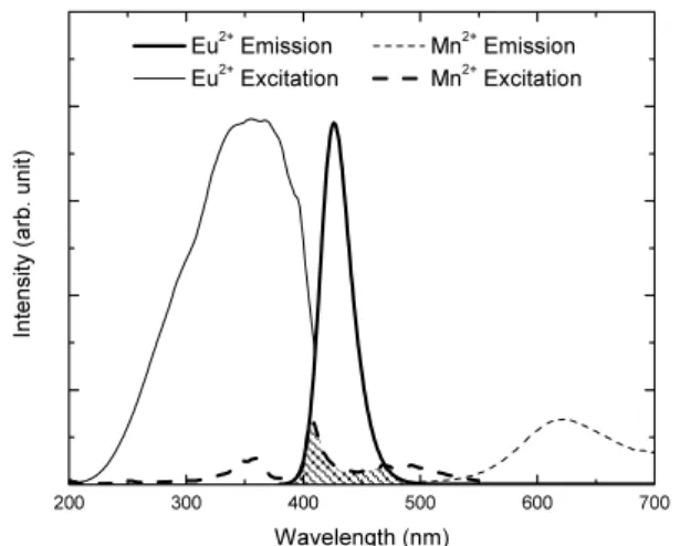
Figure 1 shows PL and PLE spectra of (Sr0.88,Ca0.1)2P2O7:0.02Eu2+ and (Sr0.78,Ca0.1)2P2O7:
0.12Mn2+. Emission and excitation of Eu2+ occur
through the general 4f6d1 ↔4f7 transition. The
concentration of the Eu2+ single-doped phosphor was
fixed at 0.02, where the emission was the most intense. The excitation peaks of (Sr0.78,Ca0.1)2P2O7:0.12Mn2+
around 360, 405, and 480 nm, and the shoulder around 420 nm, correspond to the transitions from 6A
1 to 4T2, 4A
1/1E, 4T1, and 4T2 in the 3d levels of Mn2+,
respectively [2,3]. The emission of the phosphor occurs through the spin-forbidden transition from 4T
1
to 6A
1. Due to the spectral overlap between the
excitation of the activator and the emission of the sensitizer (shaded region in Fig. 1), effective energy transfer from Eu2+ to Mn2+ is expected in the co-doped
phosphor.
The luminescent properties of (Sr 0.88-xCa0.1)2P2O7:0.02Eu2+,0.10Mn2+ phosphors in devices
were examined by loading them in UV-LED lamps. Figure 2 shows the luminescent spectra of an UV-pumped white LED composed with red, green, and blue phosphors, which are normalized with the intensity of the UV emission at around 400 nm. Green and blue phosphors used in this test were Sr2Ga2SiO7:Eu2+ and Sr5(PO4)3Cl:Eu2+. (Sr0.76,Ca0.1)2
200 300 400 500 600 700 Eu2+ Emission Mn2+ Emission Eu2+ Excitation Mn2+ Excitation In te ns ity (a rb . u ni t) Wavelength (nm)
Fig. 1. PL and PLE spectra of (Sr0.88,Ca0.1)2P2O7:
0.02Eu2+ and (Sr
0.78,Ca0.1)2P2O7:0.12Mn2+.
Fig. 2. Spectra of UV-pumped white LED with red, green, blue phosphors, which are normalized with the intensity of UV emission operating from 10 to 70 mA.
P2O7:0.02Eu2+,0.10Mn2+ was selected as the red
phosphor. In operating LED lamps, the brightness of the red phosphor showed saturation with increasing input current from 10 to 70 mA, differently from the green and blue phosphors.
The brightness saturation of the red phosphor can be quantitatively explained by considering the power conversion efficiency (PCE). The PCE is defined as
em ex ext
Q ×λ /λ , where Qext is the external quantum
efficiency of a phosphor in a LED lamp, while λex
and λem are wavelengths of excitation and emission,
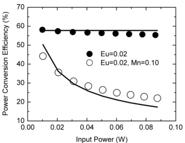
respectively. As the input power (UV flux) of UV LED increases from 10 to 88 mW, the PCE of (Sr 0.88-xCa0.1)2P2O7:0.02Eu2+,0.10Mn2+ reduces from 44 to
23%, as shown in Fig. 3. In contrast, (Sr0.88Ca0.1)2
P2O7:0.02Eu2+ shows the almost constant PCE with
variation of UV flux. It is known that the saturation of luminescence originates from a ground state depletion of Mn2+ activator due to its relatively long decay time
compared to photon influx [7-9]. However, it is not a clearly speculated explanation about the phenomenon. In order to understand the relation of PCE and light influx, rate equations for the luminescence of single-activator-doped (Eq. (1)) and co-doped phosphors (Eq. (2)) were examined: The energy transfer between excited Mn2+ ions and the energy transfer from Eu2+ to
excited Mn2+ were taken into account, as well as the
energy transfer from Eu2+ to ground Mn2+ [8-10]. For
simplification, it was assumed that the energy influx to Mn2+ ions originated only from the excited Eu2+ in
4-3 / T.-G. Kim • IMID 2009 DIGEST 0.00 0.02 0.04 0.06 0.08 0.10 10 20 30 40 50 60 70 P ow er C on ve rs io n E ffi ci en cy (% ) Input Power (W) Eu=0.02 Eu=0.02, Mn=0.10
Fig. 3. Dependence of power conversion efficiency of (Sr0.88,Ca0.1)2P2O7:0.02Eu2+ (solid circle) and (Sr0.88-x,Ca0.1)2P2O7:0.02Eu2+,0.1Mn2+ (open circle) on the input UV flux. Solid lines are the calculated results based on Eq. (1)–(4).
the co-doped system, and UV light was provided for sufficiently long time; the luminescent process was in the steady-state condition.
( ) Eu Eu Eu Eu Eu Eu dt d τ ρ ρ ρ φσ ρ * * * − − = (1) ( ) co Mn co Mn co Mn ET co Eu co Eu co Eu co Eu co Eu Eu co Eu dt d _ * _ _ * _ _ * _ * _ _ * _ ρ ρ ρ τ ρ τ ρ ρ ρ φσ ρ − ⋅ − − − = co Mn co Mn ET co Eu _ * _ * _ * ρ ρ τ ρ ⋅ − , (2a) ( ) co Mn co Mn co Mn ET co Eu co Eu co Eu co Eu co Eu dt d _ * _ _ * _ _ * _ * _ _ ρ ρ ρ τ ρ τ ρ ρ ρ − ⋅ + = − ( * ) _ _ _ * _ * * _ co Eu co Eu Eu co Mn co Mn ET co Eu φσ ρ ρ ρ ρ τ ρ ⋅ − − + , (2b) co Mn co Mn co Mn co Mn co Mn co Mn co Mn ET co Eu co Mn dt d _ * _ _ * * * _ _ * _ _ * _ * _ τ ρ τ ρ ρ ρ ρ τ ρ ρ − + − ⋅ = co Mn co Mn Mn ET co Mn co Mn co Mn ET co Eu co Mn co Mn _ * _ ) ( * * _ _ * _ * * _ _ * _ ρ ρ τ ρ ρ ρ τ ρ τ ρ ⋅ − ⋅ − − , (2c) ( ) co Mn co Mn co Mn ET co Eu co Mn co Mn co Mn co Mn dt d _ * _ _ * _ _ * _ * _ _ ρ ρ ρ τ ρ τ ρ ρ ρ − ⋅ − = − , (2d) co Mn co Mn co Mn co Mn Mn ET co Mn co Mn co Mn ET co Eu co Mn dt d _ * * * _ _ * _ ) ( * * _ _ * _ * * _ * * _ τ ρ ρ ρ τ ρ ρ ρ τ ρ ρ − ⋅ + ⋅ = , (2e)
where ρEu , ρEu _co , and ρMn_co are densities
(numbers per volume) of Eu2+ in the single-doped,
Eu2+ in the co-doped, and Mn2+ in the co-doped
phosphors, respectively. The superscripts * and ** indicates the excited and the upper excited states of each activator. τEu , τEu _co and τMn _co are the
decay times of Eu2+ in the single-doped phosphor,
Eu2+ and Mn2+ in the co-doped, respectively.
co Mn _*
τ
is the time of relaxation from the upper excited level to the excited level (4T
1) of Mn2+ in the co-doped
phosphor. τET, τET*, and τET* Mn( ) are the times of
energy transfer from Eu2+ to ground Mn2+, from Eu2+
to excited Mn2+, and from Mn2+ to excited Mn2+ in the
co-doped phosphor, respectively. φ is the photon
flux applied to the phosphors. σEu is a photon
absorption cross section of Eu2+.
Equation (1) simply states that the time derivative of excited Eu2+ concentration is determined by the
difference between rates of excitation (input) and decay (output) in a Eu2+ single-doped phosphor.
Excited energy in Eu2+ ions in the co-doped system is
consumed through the direct emission and the energy transfer to Mn2+ ions in the ground and the excited
states, as expressed in Eq. (2a). Rate equation for the Eu2+ density in a ground level (Eq. (2b)) is reciprocal
to Eq. (2a). The first and second terms on the right-hand side of Eq. (2c) are the rates of electron inflow to the excited level in Mn2+ ions. These are attributed
to the energy transfer from Eu2+ to Mn2+ and the
relaxation of electrons in upper excited levels, respectively. The third in Eq. (2c) is the discharge rate of electrons from the emission level in Mn2+.
The fourth and fifth terms correspond to outflow of electrons by the energy transfer from Eu2+ to excited
Mn2+ and from excited Mn2+ to excited Mn2+. In Eq.
(2d), rate equation for Mn2+ density in the ground
level consists of the electron inflow by the emission and the outflow by the energy transfer from Eu2+ to
Mn2+. Excitation to the upper excited levels in Mn2+,
that is, excited-state absorption (ESA) occurs through the energy transfer from Eu2+ to excited Mn2+ (the first
in right-hand side of Eq. (2e)) and from excited Mn2+
to excited Mn2+ (the second term). The third in Eq.
(2e) describes the relaxation of successively excited electrons to the emission level of Mn2+ ions. Since the
total number of dopants is fixed during a luminescent process, the sum of all factors in Eq. (2a), (2b), (2c), (2d), and (2e) should be zero [11]. The behavior of PCE as a function of photon influx is obtained through the following relations:
φ τ ρ Eu Eu Eu Eu C PCE = * , (3)
4-3 / T.-G. Kim
IMID 2009 DIGEST •
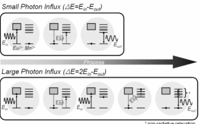
Fig. 4. Schematic diagrams of the luminescence process of Eu2+ and Mn2+ co-doped phosphor at
small and large photon influx. Energy loss during luminescence is expressed as ∆E.
φ τ ρ co Mn co Mn co Mn Eu co Mn Eu C PCE _ * _ _ , _ , = , (4)
where PCEEu, PCEEu,Mn_co, CEu, and CEu,Mn_co are the PCEs and the proportional coefficients of Eu2+
single-doped and Eu2+-Mn2+ co-doped phosphors,
respectively. The calculated PCEs are plotted along with the measured results in Fig. 3, and fairly accord with the experiment using the value of
9 *=5.0×10− ET
τ s. τET* is shorter than τET ,
which implies the energy transfer from Eu2+ to excited
Mn2+ would easily occur compared to that from Eu2+
to Mn2+ in the ground state. That is, if the ground
states of Mn2+ are depleted due to its long decay time,
the excited energy in Eu2+ will be readily transferred
to excited Mn2+ and make ESA in Mn2+ ion. The
successively excited Mn2+ ions by ESA will lose some
of their energy through the non-radiative relaxation (multi phonon relaxation) to 4T
1 level, and may
sequentially emit visible light through the radiative transition from 4T
1 to 6A1. In this process, the
frequency of the non-radiative relaxation determines the degree of efficiency drop. On the other hand, if ground states are not depleted, or photon influx rate is sufficiently small compared with Mn2+ decay rate,
quenching will not occur in Mn2+ ions. These two
processes are schematically described in Fig. 4. However, the steep decline of the PCE in Fig. 3 indicates that the quenching process begins to work from 10 mW LED power (the lowest in this test). Therefore, the luminescent quenching in Eu2+-Mn2+ co
-doped phosphors would be inevitable in the conventional LED operating power, which is usually several tens of mW at least.
4. Summary
Oxide phosphors (Sr,Ca)2P2O7:Eu2+,Mn2+ were
synthesized by solid state reaction in a reducing atmosphere, and the brightness saturation were studied. By loading (Sr,Ca)2P2O7:Eu2+,Mn2+ phosphor
on a UV LED chip, it was found that the PCEs of the phosphors dropped drastically with increasing photon influx from a UV chip. As inferred from the rate equations, the non-radiative relaxation in Mn2+ ions
resulting from excited-state absorption reduces the PCE of (Sr,Ca)2P2O7:Eu2+,Mn2+.
Acknowledgement
The authors wish to express their deep appreciation to Dr. D. H. Yeon and Dr. J. Cho for their helpful assistance with the calculations and the LED test.
5. References
1. L. S. Rohwer and A. M. Srivastava, Interface 12,
p.36 (2003).
2. W.-J. Yang and T.-M. Chen, Appl. Phys. Lett. 88,
p.101903 (2006).
3. W.-J. Yang, L. Luo, T.-M. Chen, and N.-S. Wang,
Chem. Mater.17, p.3883 (2005).
4. G. Q. Yao, J. H. Lin, L. Zhang, G. X. Lu, M. L. Gong, and M. Z. Su, J. Mater. Chem. 8, p.585
(1998).
5. A. M. Srivastava and H. A. Comanzo, US Patent 7,015,510 B2 (2006).
6. A. A. Setlur, A. M. Srivastava, H. A. Comanzo, D. Hancu, and L. J. V. Briel, US Patent 2005/0199897 A1 (2005).
7. S. Mikoshiba, S. Shirai, S. Shinada, and M. Fukushima, J. Appl. Phys.50, p.1088 (1979)
8. A. A. Setlur, J. J. Shiang, and U. Happek, Appl. Phys. Lett.92, p.081104 (2008).
9. D. M. Leeuw and G. W. ‘t Hooft, J. Lumin. 28,
p.275 (1983).
10. K. C. Mishira and M. Raukas, J. Electrochem. Soc. 151, p.H105 (2004).
11. K.-S. Sohn, Y. G. Choi, Y. Y. Choi, and H. D. Park,