Mechanical Design Features of the KALIMER-600 Sodium-Cooled Reactor
Jae-Han LEE, Chang-Gyu Park, and Jong-Bum Kim
Korea Atomic Energy Research Institute, 150 Dukjin-dong, Yuseong-Gu, Daejeon, Korea, 305-353, Email:[email protected] I. Introduction
KALIMER-600 is a sodium cooled reactor with a fast spectrum neutron reactor core. The NSSS design has three heat transport systems of a PHTS (Primary Heat Transport System), a IHTS (Intermediate Heat Transport System) and a SGS (Steam Generation System). PHTS is a pool type and has a large amount of sodium in the pool. The mechanical design targets are maintaining the enough structural integrity for a seismic load of SSE 0.3g and the thermal and mechanical loads by the high temperature environments and an economical competitiveness when compared with other reactor types.
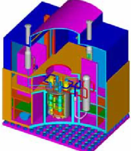
Figure 1. KALIMER-600 reactor building
2. Mechanical Structure Design Features
The main features of the mechanical structure design in KALIMER-600 are the seismically isolated reactor building, the reduced total pipe length of the IHTS, the simplified reactor support, and the compact reactor internal structures. The overall configuration of the reactor building is shown in Fig.1 and the internal configuration of the reactor vessel in Table 1 and Fig.2. The 164 seismic isolators (φ1.2m) are installed between a ground and a lower basemat of the reactor building (W49m x D36m x H54m).
The reactor vessel is the boundary of the primary heat transport system and performs support and container functions during all temperature, pressure, and load variations which occur during the operating lifetime. The reactor vessel, which is made of type 316 stainless steel, has overall dimensions of 18m in height, 11.41m in outer diameter, and 0.05m in thickness. The total reactor weight is about 2,800tons. The reactor vessel is attached to the reactor head and supports the reactor internal structures, the reactor core, and the primary sodium.
Reactor Core Support Barrel Reactor Vessel Inlet Plenum Reactor Head Containment Vessel Reactor Baffle Core Support Baffle Plate Upper Internal Structure Thermal Insulation Plate Rotating Plugs Reactor Core Support Barrel Reactor Vessel Inlet Plenum Reactor Head Containment Vessel Reactor Baffle Core Support Baffle Plate Upper Internal Structure Thermal Insulation Plate Rotating Plugs
Figure 2. Reactor Internal Configuration
The 4-IHXs and 2-PHTS pumps are installed through the holes of the baffle plate and the separation plate. The space inside the reactor vessel is thermally divided into two regions, a hot region and a cold region. The support barrel, the baffle plate and the reactor baffle form the boundary of the two regions. The reactor vessel contacts with the cold sodium of 390°C. So, the reactor vessel can maintain its structural integrity for a 60 years design life time.
Table 1 Dimension of Reactor Structure
Components Diameter (m) Height (m) Weight (tons) Reactor Vessel 11.41 18 395 Containment Vessel 11.76 18.35 158 Reactor Baffle 11.26 6.45 110 Support Barrel 5.81 11.5 67 Inlet Plenum 5.81 1.4 70
Core Support Structure 5.8 - 6.8 0.5 15 Upper Internal Structure 2.8 10.2 67 Reactor Head 11.76 0.5 239
IHX 2.4 7.9 30
Primary Sodium Pump 2.4 17 110
As for the reactor internals, a simple skirt type core support structure, integrated cylinder type support barrel, and UIS are designed. The baffle annulus structure in the reactor internals can accommodate a large thermal difference between the hot pool and cold pool region.
The upper internal structure (UIS) is attached to a rotatable plug installed on the reactor head and cantilevered downward into the reactor hot pool. The total length is 10.2m, and the two outer cylinders with a porosity are 1.5m and 3.1m in diameter. The principal functions are the lateral support of the control rod drivelines(CRDLs), the protection Transactions of the Korean Nuclear Society Autumn Meeting
of the drivelines from a sodium flow induced vibration, and the support of the above core instrumentation drywells.
The IHTS piping system connects the IHX, steam generator and the secondary EMP. The IHTS piping material is Mod.9Cr-1Mo. The hot leg piping is 60cm in outer diameter and 0.9cm in thickness, while the cold leg piping is 82cm in outer diameter and 1.1cm in thickness. Each loop has two hot leg pipe lines and one cold leg pipe line. The total length of the IHTS piping is about 109m.
The service limits of the stresses, accumulated inelastic strains, and creep-fatigue damages for the reactor structures satisfy the ASME design criteria for 40 years of the operating lifetime. Currently, the ASME code provides design data for 40 years and it is necessary to acquire the corresponding design data for 60 years or to extrapolate the 40 years data to 60 years. This is the one of challenging items for 60 years design.
The reactor head in KALIMER-600 is the top closure of both the reactor vessel and lower containment vessel. It provides mechanical supports for all PHTS components including the IHX, PHTS pumps, rotatable plug and the primary sodium. The reactor head is one piece of a welded steel plate of 50cm in thickness. It is designed to operate at under 150°C. The temperature is attained by an inclusion of 5 horizontal layers of a stainless steel insulation and shield plates, the top one of which is installed 45cm below the bottom of the reactor head.
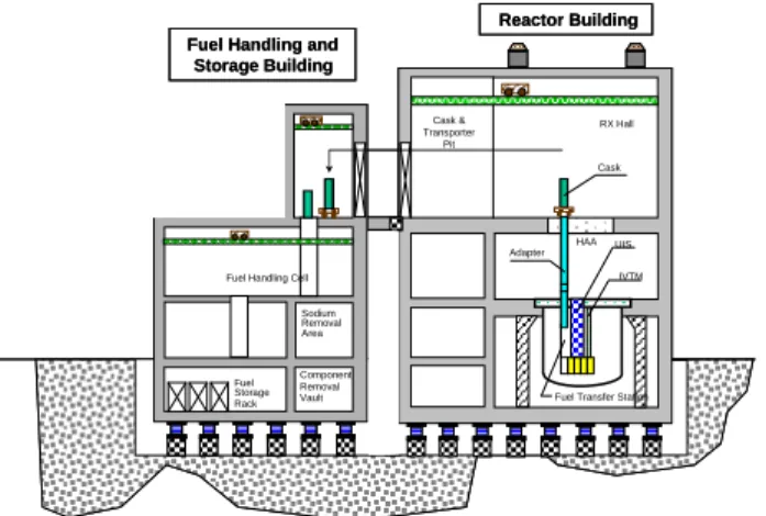
The reactor refueling system (RRS) provides the means of transporting, storing and handling reactor core assemblies, including the fuel, control, and the shield. The system consists of the facilities and equipment needed to accomplish the normal scheduled refueling operations and all other functions incident for the handling of the core assemblies.
Fig.3 depicts the arrangement of the RRS. The system consists primarily of the in-vessel transfer machine (IVTM), the double rotatable plug drive, and the fuel transfer port which are located entirely within the reactor.
Reactor Building Fuel Handling and
Storage Building Cask & Transporter Pit RX Hall Cask UIS Adapter
Fuel Transfer Station IVTM HAA Fuel Handling Cell
Sodium Removal Area Fuel Storage Rack Component Removal Vault Reactor Building Fuel Handling and
Storage Building Cask & Transporter Pit RX Hall Cask UIS Adapter
Fuel Transfer Station IVTM HAA Fuel Handling Cell
Sodium Removal Area Fuel Storage Rack Component Removal Vault
Figure 3. The arrangement of the reactor refueling system (RRS)
The KALIMER-600 design contains features which provide a defense-in-depth for a full spectrum of severe accidents including a hypothetical core disruptive accident (HCDA) and a core melt. The containment shown in Fig.4 provides a low leakage, pressure-retaining boundary which
completely surrounds the primary system boundary. It includes a lower containment vessel designed to contain reactor vessel leaks and an upper containment structure with a liner which will mitigate severe events, such as a HCDA, which are postulated to cause an explosion of radio-nuclides through the reactor head into the region above the reactor.
Upper Containment Structure with Liner
Support Wall Containment Vessel Crane Working Floor Reactor Vessel Upper Containment Structure with Liner
Support Wall Containment Vessel Crane Working Floor Reactor Vessel Upper Containment Structure with Liner
Support Wall Containment Vessel Crane Working Floor Reactor Vessel Upper Containment Structure with Liner
Support Wall Containment Vessel Crane Working Floor Reactor Vessel
Figure 4. Schematic Drawing of the Containment Dome The lower portion of the containment consists of a 2.5 cm thick and 11.76 m diameter vessel, which has no penetrations and is designed to remain essentially leak tight. The annulus between the reactor and containment vessel is filled with argon and maintained at a higher pressure than the reactor cover gas. The concrete support wall maintains its low temperature by an adoption of a Cavity Cooling System which operates passively between the containment vessel and the surrounding support wall.
The upper containment structure is composed of a thick concrete rectangular structure with a dome, and a metal liner is attached inside the containment structure. The thick concrete rectangular structure with a dome structure provides a solid barrier for protecting interior structures against all kinds of external loadings including an aircraft crash.
3. Conclusions
The developed conceptual design can satisfy its design requirements to achieve the KALIEMR development targets, an enhanced safety and competitive economics.
Acknowledgement
This study was supported by the Korean Ministry of Science & Technology through its National Nuclear Technology Program.
REFERENCES
[1] Lee, Jae-Han, et al, Summary of Structural Concept Design and High Temperature Structural Integrity Evaluation Technology for KALIMER-600 Liquid Metal Reactor, KAERI/TR-2938/2005. [2] Lee, Jae-Han and Park, Chang-Gyu, Structural Design Concept Comparison for KALIEMR-600 and JSFR-1500, KNS 2005 Spring conference, 2005.