Comparison of Creep Fatigue Damage for Welded Cylindrical Structure according to the
design rules of ASME-NH and RCC-MR
S. H. Kim, H. Y. Lee, Y. S. Joo, J. H. Lee
Korea Atomic Energy Research Institute, Daejeon 305-600, Korea, [email protected] 1. Introduction
Creep-fatigue is an important failure mode in elevated temperature components especially for weldments. The creep fatigue test was carried out with a hold time of one hour at 600oC and the primary nominal stress of 45MPa for the specimen. Also, the evaluation procedures of creep fatigue damage for the welded structure according to design rules of ASME-NH and RCC-MR are presented. To compare the design by analysis methods for the weldments, the creep fatigue damage was evaluated in the vicinity of the weld.
2. Methods and Results
2.1 ASME-NH (1) Damage Equation
For a design to be acceptable, the creep and fatigue damage shall satisfy the following relation and the total damage D shall not exceed the creep fatigue damage envelope of Fig. 1[1]: D T t N n P j q k d d ≤ ∑ + ∑ ∆ =1( ) =1( ) (1) D : total fatigue creep damage
j d N )
( : number of design allowable cycles
k d T )
( : allowable time duration (2) Strain Range Determination
The equivalent strain range is computed as follows.
xo xi xi ε ε ε = − ∆ (2) yo yi yi ε ε ε = − ∆ (3) ] ) ( 2 3 ) ( ) ( ) ( [ *) 1 ( 2 2 2 2 2 2 2 2 , zxi yzi xyi xi zi zi yi yi xi i equiv γ γ γ ε ε ε ε ε ε ν ε ∆ + ∆ + ∆ + ∆ − ∆ + ∆ − ∆ + ∆ − ∆ + = ∆ (4)
The total strain range is calculated as:
c v t K ε K ε ε = ∆ mod + ∆ (5) ) 0 . 1 ( 0 . 1 + ' − = v v f K K (6)
K : local geometric concentration factor v
K : the multiaxial plasticity and poission ratio adjustment
factor
c
ε
∆ : the creep strain increment
mod
ε
∆ : the modified maximum equivalent strain range (3) Creep Fatigue Reduction Factors for a weldment In the vicinity of a weld(defined by ±3 times the thickness to either side of the weld centerline), the
d
N value shall be one-half the value permitted for the
parent material. The T value shall be determined by d
using the weld strength reduction factors given in table I-14.10, and defined in NH-3220[2]. The factor K (TableT-'
1411-1) must still be applied in this determination of T . d
2.2 RCC-MR
(1) Limitation of Creep-Fatigue Damage
The total strain ranges including the amplification of strain due to plasticity and creep can be obtained from the results of stresses obtained by an elastic analysis and the above eq.(1) presents the limit rule of the accumulated creep and fatigue damage.
(2) Total strain range
( )
εelpl εcrε = ∆ + ∆
∆ +
(7)
In equation(8), the elastic plus plastic strain range,
( )
∆ε el+plcan be obtained using the sum of the four straincomponents considering the amplification due to plasticity as following[3];
( )
∆ε el+ pl = ∆ε1+ ∆ε2 + ∆ε3 + ∆ε4 (8)(3) Creep Fatigue Damage for a weldment
For weld metal, the RCC-MR proposes to apply a reduction factor =1.25
f
J (for 316L steel) on the strain
variation of the associated base metal fatigue curve. The
Transactions of the Korean Nuclear Society Autumn Meeting Busan, Korea, October 27-28, 2005
time to rupture per cycle was calculated with the real creep rupture stress of the base metal multiplied by the
r J
coefficient depend on time and temperature. The creep damage factor for welded joints was calculated with
r J as )) / 9 . 0 ( / ( i r d c J T t D σ =
(9) where t is holding time and
d
T is rupture time[4].
2.3 Analysis Model
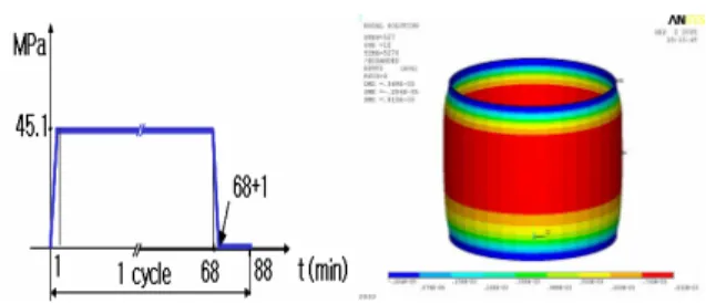
The test specimen is a welded cylinder type which is composed of 316L stainless steel. The thermocouples were attached along the inner surface of the cylinder and the temperature history of the thermal loads which are applied to the specimen was measured as shown in Fig. 2. Also, the tension load is applied to the welded specimen in the axial direction at the top surface as shown in Fig. 3. The ANSYS finite element model of the welded specimen used a 2D axisymmetric model.
2.4 Analysis Results
The creep-fatigue damage according to the design rules of ASME-NH and RCC-MR was evaluated for 600 load cycles. In case of ASME-NH, the equivalent strain ranges at three points in the vicinity of a weld were calculated. The maximum equivalent strain range was decided in the HAZ region with the height of 22.9Cm from the bottom. The total strain range calculated using eq.(5) was 0.000413 and the distribution of total hoop strain was presented in Fig. 3. The fatigue and creep damage for the above position were evaluated as 0.000333 and 0.006148, respectively. In case of RCC-MR, the fatigue and creep damage in the same position as ASME-NH were evaluated as 0.000165 and 0.001583, respectively.
3. Conclusions
In this paper, a creep-fatigue test with a welded cylindrical specimen has been carried out and the test results were compared to those by the elastic analysis according to the design rules of RCC-MR and ASME-NH. The evaluation results showed that the creep fatigue damage was very small and the creep damage was dominant over the fatigue damage on both RCC-MR and ASME-NH. The actual observation results for the welded zone using an optical microscope did not show any visible damage after 600 creep fatigue load cycles, which are in agreement with the evaluation results.
Acknowledgements
This work has been carried out under the Nuclear R&D Program by MOST in Korea.
REFERENCES
[1] ASME Boiler and Pressure Vessel Code Section III, Subsection NH, ASME, 2004.
[2] L.K. Severud, Creep-fatigue assessment methods using elastic analysis results and adjustments, Transactions of the ASME, Vol. 113, p34-40, 1991. [3] Design and Construction Rules for Mechanical Components of FBR Nuclear Islands Section I, RCC-MR,
2002.
[4] Naoto Kasahara, Laurent Le Ber and Stephane Chapuliot, CEA and JNC aproaches for creep-fatigue evaluation of weldments and inter-comparison through benchmarck analyses, Nuclear Engineering and Design, P120-142, 2002.
Fig. 1 Creep fatigue damage envelope
Fig. 2 Welded specimen and the position of thermocouples
Fig. 3 Mechanical load and distribution of total hoop strain in welded specimen