bbbbbbbbbbbbbbbbbbbbbbbbbb
1. Introduction
The fieldbus is three-layered real-time communications network for control and automation with digital, duplex, multi-drop, and serial-bus properties.[1][8]. In the open standardization works of fieldbus, several models has been competing fiercely in each applicable field or in their technical specification proposed from various country. The fieldbus standard IEC 61158, Completed in 2000, accommodates 8 different fieldbus standards proposed several vendors, and the IEC61784-1 announced on May 2003, contains 10 kinds of fieldbus including Ethernet/IP in 7 CPFs(Communication Profile Family) making up 18 different profiles[2][3][4]. These various standardizations makes the co-existence or the inter-operability in physical layer or in data link layer impossible. And in order to solve these problems in the application layer, the ISO-15745, XML-based "Open system application integration framework" was proposed[5]. However, the North American standard FF (Foundation Fieldbus) which is regarded as providing the strongest environment for distributed control system, and the SwiftNet did not participate in the ISO-15745. And moreover, 5 kinds of fieldbus are pursuing to join newly in ISO-15745,
So, much criticism in the inter-operability between heterogeneous fieldbus is predicted in the future. Also, even if inter-operability through the ISO- 15745 becomes possible, excessive cost to implement the XML application will be unavoidable. And products with different physical device standards or different datalink protocols will either divide the market or mixed in the control filed, which on the user's perspective, will not help in reducing construction costs or cuts in operation expenses.
The delay of standardization about the fieldbus, and complexity or variety in standard specifications, as well as high prices, have been an obstacle to wide spread of the fieldbus in the industry. It is especially hard to find the fieldbus applied in domestic or foreign power plants or chemical plant having large scale IO points, Most control automation communications systems of foreign and domestic
power plant still use a particular vendor specific closed communications structure and protocol. Also, the network of the DCS(Distributed Control System), recently expanding in the national power plant, have special closed-models of vendors', which makes the dependency of installation, maintenance, and repair high on that vendor. So these systems not only raise installation cost, but also bring many difficulties to maintenance and extension.
Therefore, to overcome these problems, this paper introduces a development of an "PC/Ethernet based fieldbus architecture and protocol" to be used in mid-level fieldbus, which has low implementation cost and accommodates large-scale input-output(IO) points existing power plant or process control plant
Recently, the industrial Ethernet has been adopted in the commercial fieldbus in various forms. But there are many differences in the protocol architecture or application area between these and this thesis's fieldbus. For example, the FF-HSE(Foundation Fieldbus - High Speed Ethernet) or FROFINet, these are not the traditional 3-layered fieldbus, but the 5 layered fieldbus including the TCP/IP layer.[6] And these is mainly used as a higher information level network instead of the field-level real-time control network. The Ethernet/IP (Industrial Protocol), which attracts public attention lately for the field level real-time control communications network, also includes the TCP/IP layer, and more over, it holds a protocol CIP (Common Interface Protocol) on the TCP or UDP, and another user's object is operated above it[7]. These thick-layered architecture bring many limitations to realize realtime control communication system which has large volumes of control points in the tens of thousands,
However, the PC/Ethernet based fieldbus proposed in this thesis, keeps the basic concept of the thin three-layered fieldbus architecture by using the "fieldbus Over Ethernet", which helps to realize the high speed realtime communication for the control system that has huge scale of IO control points.
A Development of PC////Ethernet based Fieldbus Network
for Large Realtime Data Communication
Kwi-Yil Gwak*, Sung-Woo Lee**
* Department Korea Electric Power Research Institute. Daejeon, Korea (Tel : +82-42-865-5972; E-mail: [email protected]) ** Department Korea Electric Power Research Institute. Daejeon, Korea
(Tel : +82-42-865-5396; E-mail: [email protected])
Abstract: Control network adopted in the national power-plant or manufactory are mostly vendor-dependent products, which have their own special specification, components and individual communication methods. These systems not only raise installation cost, but also bring many difficulties to maintenance and extension. To overcome these problems, this paper introduces a development and application case of a new "PC/Ethernet-based fieldbus" architecture and protocol to be used in mid-level fieldbus. The designed system has a basic idea of "3 Layers fieldbus over Standard-LAN" and implemented on PCs. PC gives user friendly environment. By using an open standard Ethernet in layer 1,2, the system has low cost, wide communication bandwidth and high compatibility. Layer 3 protocol designed for large realtime data communication makes user bypass TCP/IP layer and gives user direct access to the Ethernet. This new protocol eliminates potential collision of Ethernet, and transmits large periodic/non-periodic control data by using long-frame/wide-bandwidth of Ethernet effectively, and offers simple API-Services to the upper layer. Since the system have installed in H-power plant simulator and U-nuclear power plant simulator in Korea, it have been proved to be efficient and stable without any trouble in realtime communication service for full-scope plant simulator that has a lot of control elements.
And also, it gives good advantages to accomodate the existing IO control point devices with no io device-changing.
2. Overview of the Target System
2.1 Components and Requirements of the System
The target application area of the designed fieldbus network are large-IO scaled realtime control and automation system such as plant control system or plant simulator system which have the I/O points of more than 20,000 points, assuming that the required realtime cycle is less than 100msec. And about devices, the thesis assumes that the most of IO devices including sensor and actuator, etc are conventional devices in which no intelligent protocol or program is exists.
So, the newly designed fieldbus is a mid-level filedbus which accommodates the exiting conventional IO point by the PC-based IO-card.[11] This fieldbus system has the distributed control nodes which can collects signals from conventional devices, and these distributed nodes supports realtime communication among them, that means the med-level fieldbus. Of course, every distributed node can contains the lowest level fieldbus protocols like RS-485. The NIC(Network Interface Card) used for the implementation is Ethernet, open international standard, and distributed control nodes are industrial PCs. The communication protocol between nodes is the realtime communication protocol VTBP(Virtual Terminal Box Protocol), that was developed by KEPRI(Korea Electric Power Research Institute) for large-scaled IO realtime communication[10]. The VTBP(Virtual Terminal Box Protocol) has 3-layer architecture, and it also supports 5-layer architecture including TCP/IP at the same time in parallel.
2.2 Conceptual Diagram for the fieldbus System
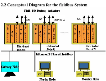
Fig. 1. Concept of the PC/Ethernet based fieldbus Comprehensive conceptual diagram for fieldbus System is showed above. The distributed node based on PC is located in each control field. These distributed nodes can have IO card installed inside and, if necessary, remote RS-485 cards can be added. The network layer 1st and 2nd in each node is processed by LAN card and the 3rd layer (application layer) is processed by VTBP(Virtual Terminal Box Protocol).
One of the distributed nodes in the picture becomes the control node for communication network ("Master node") and controls the right of medium access. The master node here plays same roles as BA(Bus Arbitrator) of IEC 61158 Type-7(WorldFIP) or LAS(Link Active Scheduler) of FF
standard.[3][6]
Another node can be chosen as "Monitor node" which detects the status of master node, and plays the backup functions of the master node when the master node is in trouble.
One of nodes can be selected as "Gateway node." Gateway node gives link path, between the fieldbus network and outside network, In chapter 4 of this thesis, the simulation computer plays the role of the gateway node.
And the other distributed nodes is the IO-Node or Sub-node, Sub-node(IO-node) has IO cards for connection to the Input/Output signal point of conventional devices, or the lowest level fieldbus devices, and performs actual working of input/ output under the control of the master node.
3. The Design and Implementation of the Protocol Architecture
3.1. The Design of Protocol Architecture
In general, the recent fieldbus based on the Ethernet has 5 layers architecture including TCP/IP layer mostly, like Ethernet/IP and FF-HSE, etc. But the PC/Ethernet-based fieldbus developed in this thesis effectively provides high speed realtime services for the large-io-scaled control system through the traditional thin model of 3-layer fieldbus architecture. The designed protocol structure is shown in the picture below.
Fig 2. Designed Protocol Architecture
The fieldbus system introduced in this thesis is equipped basically with the TCP/IP communication stack shown as Fig.2(a). This TCP/IP is used only for non-realtime communication with explicit messages such as setup file or various types of parameters at the initialization or setup process. But for realtime communication of cyclic and uncyclic data which are used in normal operation, the layer 3 communication structure is used by direct accessing to the Ethernet, like shown as Fig.2(b), letting the VTBP layer protocol bybass TCP/IP protocol . The problem of medium collision of Ethernet can be solved by extended control function at the VTBP layer.
○ the layer 1, 2(Physical and Data-link layer)
Since using standard Ethernet, it inherits the specification and characteristics of Ethernet. That is, standard Ethernet, such as 10Base2, 10BaseT and 100Base-T4/TX/FX are usable in the fieldbus network. The CSMA/CD (Carrier Sense Multiple Access/ Collision Detect), the conventional MAC for Ethernet, is not suitable for realtime communication because of its protocol characteristics of contention and collision. But, if special access control that prevent from the collision, is
NIC MAC NIC PHY TCP/UDP IP Interface Layer 1
Layer 2 NIC MAC NIC PHY b) Realtime Control Data App Layer Protocol VTBP
Interface
a)Explicit Non-RT Data Layer 3 Layer 4 Application Process NIC MAC NIC PHY TCP/UDP IP Interface Layer 1
Layer 2 NIC MAC NIC PHY b) Realtime Control Data App Layer Protocol VTBP
Interface
a)Explicit Non-RT Data Layer 3 Layer 4 Application Process
added on the layer of Ethernet as shown in this thesis, then the Ethernet that has wide bandwidth and long data frames can be used effectively for realtime communication. If full-duplex optical line, such as 100 BaseFx, is used, then the fieldbus for wide area can be setup with less cost through Ethernet. ○ Upper layer interface of Ethernet
Industrial standards of upper layer interface of Ethernet are Packet Driver and NDIS(Network Device Interface Specification), etc for PC-based system, and DLPI(Data Link Provider Interface) for Linux system.[13] In this system, NDIS and Packet Driver are used.
○ Application Layer (layer 3, VTBP layer)
The application layer of this fieldbus is the VTBP(VTBP:Virtual Terminal Box Protocol) developed by KEPRI[10]. The VTBP protocol provides high speed, realtime communication service for large-scaled IO control signal points by direct accessing to the LAN card through bypassing TCP/IP layer. The name, VTBP, comes from the meaning that it gives virtual image such as "Virtual Terminal Box" to application user.
○ Upper user layer (Application Layer)
User application is located in upper layer of distributed control node. It can bring the data obtained from input cards to the VTBP layer, and get the data from the VTBP layer to output to output cards. In doing this, approach to VTBP layer is done by VTBI interface function that is provided by VTBP layer.
3.2 Design of VTBP components and function 3.2.1. Major Function Modules of VTBP layer
Centered around VTB, there are 3 major functional modules in VTBP layer as shown in the picture below.
VTB 확장 MAC VTBI 서비스 고속 블록 버퍼 전송 다른 노드의 VTBP 계층 하위계층 상위계층 Other Node’s VTBP Layer Service Extend. H ig h S p ee d B lo ck B u ff er T ra n sf er Lower Layer Upper Layer VTB 확장 MAC VTBI 서비스 고속 블록 버퍼 전송 다른 노드의 VTBP 계층 하위계층 상위계층 Other Node’s VTBP Layer Service Extend. H ig h S p ee d B lo ck B u ff er T ra n sf er Lower Layer Upper Layer
Fig 3. Major function of VTBP Layer
○ Extended MAC(Extended Medium Access Control) : Access control to the lower Ethernet medium for collision-free mechanism.
○ Transmitting of high-speed Block Buffer : High speed exchange of data buffer information (VTB) through network. ○ API Service : Services to upper layer applications. It provides abstract programming environment.
3.2.2 VTB - Virtual Terminal Box
VTB is an object that is created by modeling of field's terminal box into PC memory and it exists in the VTBP layer.
It means that, the VTB is an data image buffer, which contains cyclic and non-cyclic realtime data of each node, and it delivers virtual terminal box image to users. Inside of VTB, logical IO points(DI/DO/LO/RO, AI/AO) which represent the physical IO points of plant is exist, and the VTBP protocol use the function of "High-speed Block Buffer Transmission" to exchange and refresh the information of the VTB. In such process, VTB information value can be maintained as the current values always and the users can read or write the values of current data set.
3.2.3. Extended Medium Access Control: Collision-Free Extended MAC
The extended MAC controls the access right of Ethernet medium among multiple nodes so that they won't have the collision. To allocate the access right, the master node (communication control node) uses the polling method to other nodes. And the node that gets the access rights broadcasts its input signal of VTB information to the fieldbus network, and the other nodes refresh their VTB information and refer to it when needed. The extended MAC provides the access control similar to the Producer/Consumer model of WorkdFIP and FF standard, and the master node plays the role
of BA(Bus Arbitrator) or LAS(Link Active Scheduler).[3][6]
3.2.4 Data Transfer Cycle
The VTBP protocol has simple and effective policy of transfer cycle. By using the wide bandwidth of Ethernet actively, the VTBP uses "Cyclic Status Transfer" concept, that broadcasts all current state data cyclically in the minimum required cycle period. But it can prevent excessive hunting of each device by recording or reading the current value from/to VTB with the cycle that each application wants.
The cyclic sending period, Ts, in that period all data are actually sent, is set to the half of minimum required cycle period, T1.
Ts = T1/2
Using this sending method of transfer cycle, the sampling data in any receiving node from the VTB is not older than T1, which means that the requirement of sampling period is observed.
3.2.5 High-Speed Block Buffer Transfer
As mentioned above, VTB(Virtual Terminal Box) is data image buffer for the cyclic/non-cyclic control point of nodes. Each control point reserves continuous space in the VTB when protocol is running.(Digital signal is 1 bit and analog signal is 2 Byte long). Inside of the VTB itself, all control data are blocked, and control data identification are defined by the relative location in the buffer, and some part of VTB becomes the payload of Ethernet frame.
The VTBP(Virtual Terminal Box Protocol) layer exchanges the VTB information with peer VTBP layers with independence on the upper layer application. That is, the sending VTBP sends the VTB image buffer information to the network in the predefined cycle, regardless of the request of applications. And the receiving VTBP layer receives the VTB information and updates the image buffer, regardless of request from application. These buffer management and automatic refreshing method are similar to buffer exchange concept of WorldFIP standard and QNU(Queued Network Updated) service of FF standard.
The VTB of each node is composed of sending part and receiving part. The Sending part is data set which is created(published) and updated by own node itself, and
receiving part is data set which is created by other node and updated by network's receiving event.
The opening of the data transfer cycle is started by the broadcast timing frame created by the master node. The each node connected the network receives this polling message and gets the access right in the order. The node catching the access right broadcasts their own data(publishing or producing data) of VTB buffers to the network and all the other nodes refresh the information if needed as the customer nodes.
3.2.6 Error Control
The VTBP protocol uses the connectionless method using broadcasting of VTB block buffer. If sending/receiving Ethernet frame contains error this frame is discarded by CRC check of Ethernet layer. The missing data frame has current status, and the next frame reflecting current status will be arrived by High-Speed Block Buffer Transfer within 1/2 of minimum required cycle. So missing information are redelivered faster than ARQ request mechanism..
3.2.7 Structure of Send/Receive Frame
The frames of 1st and 2nd layers are Ethernet. The Frames are composed of Ethernet header, user data (payload) in max 1500 byte long, and FCS.
Fig.4. Ethernet Frame and VTBP PDU Structure Here, the Ethernet payload is used by VTBP layer and contains VTBP Sender/Receiver addresses, control code, and SDU information of VTBP layer.
The VTBP SDU structure after the control code is several types composed of different elements including timestamp according to version. Also, there are many different data format, Text, Fixed-IO, Named-Variable data, etc according to control codes. The example in Chapter 4 is example using Fixed-IO format in simulator.
3.3 Upper Level (Application Proram) Interface
API(Application Program Interface) is a interface function that is provided from lower layer to service upper layer entity. The API of VTBP layer is the VTBI(Virtual Terminal Box Interface), a kind of object-oriented class, implemented with C++ tool.
Especially, the VTBI function can be used easily by any user because it's composed of similar name and usage to "Input/Output function of PC Hardware Port" like "GetPort, PutPort" which is well known to PC programmers. 3.3.1 Concept and Location of VTBI
The VTBI is SAP(Service Access Pointg) which is provided to upper layers by VTBP layer as the "Socket" interface of TCP/IP. The VTBI, as seen in the Figure, is located at the top of VTBP and provide the function with which user can approach to VTB. The developer of application programs
using VTBI needs no knowledge about detail actions of VTBP layer or networks, and they can access simply to I/O points and control variables via Put/Get functions provided by VTBI library.
Fig. 5. The Location of VTBI
The numbers and types of I/O Point, and control variable which can access via VTBI can be set during system setup process.
3.3.2 Functions and usage of VTBI
The VTBI provides various functions to support realtime Input/Output process through the library, in which functions for creation, deletion, open/close of VTBI, and functions for reading/writing of IO variables or control variables by the unit of bit, byte, word, are included. Using steps of VTBI service primitives are as follows.
New VTBI Open VTBI Put/Get (read/ write) Close VTBI Delete VTBI
Fig.6. Call Sequence of VTBI Primitives
User creates VTBI (New VTBI) by declaring the VTBI object in his program. and user opens VTBI using VTBI library function (Open VTB). If the VTBI is opened normally user can call various Put/Get functions to write(read) to(from) the VTB data. That is, a sender sends the signals to the network using put function and a receiver receives the signals using get function. The application program which completes sending or receiving of data and action of control job can close(Close VTBI) the VTBI.
3.3.3 Logical Address Convention of I/O Point
Physical I/O point can be approached by logical addresses in VTBI function. The logical address is composed to represent the physical location, so the user can infer physical point from logical address intuitively. The logical address is used as a function parameter for each VTBI function call. The example of the address convention is shown below. ○ Designed Hardware Address(I/O Point Name) NxxxTTxxCxxx
┃ ┃ ┃ ┗--> Channel-id in each Card Slot ┃ ┃ └---> Card-id of each IO type/Node ┃ └----> I/O Type Identifier
└--> Node-id, unique within whole system
4. Application and Performance Analysis
This chapter shows a realized example and performance analysis about the designed fieldbus, which has distributed IO node having large-scaled control point in the amount of
around 20,000.
This fieldbus system is applied to the H-thermal power plant simulator and U-nuclear power plant simulator in Korea. Those simulators are modeling case of the full scope plants that have a lot of control elements and IO Point. Since the system have installed in there, it have been proved to be efficient and stable without any trouble to serve realtime communication. Here, we are using the example of the latter. 4.1 Size of the System and Node Construction
The realtime I/O points that are handled by U-nuclear power plant simulator including the 15% excess points are same as the table below specifies
Table 1. I/O point capacity of U-NP simulator Input Output
. IO
Type DI AI DO RO AO Total Points 4,736 480 9152 480 1632 16480 Total I/O points are assigned to multiple distributed nodes. The number of nodes varies according to the number of IO points. In this thesis, 14 distributed nodes is constituted after considering the location of panel, partition of IO point, frame length of the Ethernet, and overheads that is latent in protocol. In addition, master node and monitor node are added to the network, and one simulation computer is prepared to provide the role of the gateway.
The master node and monitor node are based on the windows platform and the upper layer interface of VTBP is implemented by NDIS. Distributed control nodes can be set up in Window, DOS, and Linux systems. NDIS interface for the Windows, and Packet Drive interface for the DOS are used for H-thermal power plant and U-nuclear power plant respectively. For IO card, ISA Bus Cards, the PC standard, are used mostly but there are models implemented with PCI Bus.
For communication network, H-thermal power plant employed 10 Mbps Ethernet, and U-nuclear power plant employed 100Mbps Ethernet and switch. The required minimum data scanning cycle for simulation is 100ms. Hence, the data transfer cycle is set to 50msec, which is 1/2 of 100ms. 4.2 Performance Measurement & Analysis
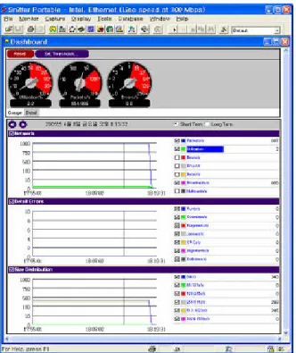
The figure-7 is the result of network analyzer measured from U-nuclear power plant simulator to check various performance variables for about one hour.
4.2.1 Error/Collision Rate Analysis
○ It shows safe and stable communication and no CRC error, Frame Length Error, or Collision on the network during the operation.
○ The Ethernet medium access is controlled by extended MAC of VTBP layer in this system, So there is no collision, and we know that this collision-free function contributes to realize realtime communication. This system yields a same result on the 10Mbps LAN simulator of H-thermal power plant.
4.2.2 Frame Rate Analysis
○ The figure shows that the regular number of frames per sec(886 frames/sec) is transmitted through the network regardless of the load and time. This is obtained because VTBP layer broadcasts all current status data cyclically in the
minimum required cycle period. So, the network can always maintain the deterministic realtime service regardless of load changes.
Fig 7. Utilization/Error/Frame size of the Fieldbus ○ Nodes that are transmitting the data are a total of 16 nodes including master node, 14 sub-nodes, and gateway(simulation) node. The designed total number of frames in one cycle for sending and receiving all data are set to 42 frames including the control frame. Hence, considering 886 frames per sec in the graph above and, considering 1 cycle has 42 frames, then "the cycles per sec" is (886/42=) 21 times and the transmitting cycle is 1/21 = about 47ms meaning the system is working well within the required values. 4.2.3. Analysis on Networking Usage Rate
○ The usage rate of communication network is about 2%, showing regular value. This means that only 2.0Mbps bandwidth of 100Mbps is used, and if the LAN was 10 Mbps Ethernet, it would took up about 20% of total bandwidth. This means the bandwidth has a lot of excess capacity that serves for more control points without delay or loss of data. moreover,
○ The reason why the usage rate is steady is, that all data is pre-scheduled to be sent, and serviced deterministic way in regular cycles. This gives the hint that the network can be used near by 100% of usage rate during normal operation. 4.2.4 Frame Size Analysis
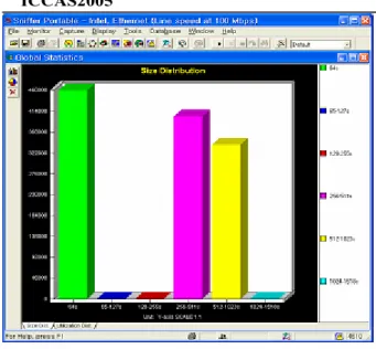
The size of frame is depending on the VTBP design. We can see 3 types of frames in the picture above. The most numerous one is 64 bytes and is used by master node for access control of the network. All the distributed node transmitted fixed 314Byte long frames and the simulation nodes fixed transmitted 586Byte long data frames. Normally, fixed length of frame tends to speed up the processing time of computers.
Fig. 8. Frame sizes of U-NP simulator Fieldlebus 4.2.5. Source/Destination Address of Frames
All 17 addresses appear in sender's address field in host address map. The receiving address field is marked with broadcasting address. So, any distributed node in the network can receive the frame and can refer to necessary information as a consumer (subscriber) of other node's data.
Fig. 9. Host Node Map
5. Conclusion
The Ethernet based fieldbus is drawing a lot of attention recently. But most of that have the TCP/IP stack and so it is very hard to realize the realtime control network that supports the high speed service as fast as 100~200msec for numerous large-scaled control points. But the suggested PC/Ethernet- based fieldbus has traditional 3-layer architecture to reduce overheads, and it is proved that it can support realtime communication within the speed of 100msec using VTBP protocol over Ethernet in an example network having about 20,000 of control points. Moreover, it provides the easy programming environment for users through the simple API which has similar to input/output port commands of intel PC. The VTBP layer has similar operation to the cyclic data processing of the standard fieldbus WorldFIP(IEC 61158
Type-7) and holds special characteristics such as LAS or Publisher/Subscriber that can be found in Foundation Fieldbus. About the object data of service target, the designed fieldbus has a strong point to serve the realtime cyclic data transfer like BNU(Buffered Network-Scheduled Uni-directional) service that can be found in FF. In BNU of FF, network protocol automatically transmits the data buffer in cyclic manner without request of sending from users. Since the fieldbus suggested in the thesis is using open standard Ethernet and PC, it has advantages of standard Off-the-Shelf product which make the cost low and give user convenience to use. And credibility, stability, expandability would comes with standard specification, and the spare parts can be easily obtained because it's vendor independent. So it will contribute to the long-term operation, educational training, maintenance and repairing too.
Although the suggested fieldbus still have some issues of further improvements such as redundancy of network module, compatibility with other fieldbus in the application layer, this fieldbus is considered as an excellent model of low-cost high-speed realtime fieldbus with large-scaled control point.
References
[1] "Overview and Guidance for the IEC 61158", International Standard IEC/TR 61158-1, p.6. 2003. 4. [2] "Physical layer specification and service definition",
International Standard IEC 61158-2, 2003. 5
[3] "Data link service definition", International Standard IEC 61158-3, 2003. 5
[4] "Profile sets for continuous and discrete manufacturing relative to fieldbus use in industrial control system", International Standard IEC 61784-1. 2003. 5.
[5] "Industrial automation systems and integration - Open systems application integration framework", ISO 15745-1, ISO TC184/SC5, 2003.
[6] Foundation Fieldbus Specification, FF-830-1.5 Data Link Protocol.
[7] EtherNet/IP Specification 1.0. Vol.1 CIP Common Specification. p.1-18, ControlNet International and ODVA, June 8. 2001.
[8] K.Y Gwak, S.W. Lee, Development of Smart Type Tramsmitter Using Fieldbus, Mid-Term Technical Report, Korea Electric Power Research Institute, 2005. 2 [9] K.Y Gwak, T.I Chang, “Design and Implementation of a
Communication Protocol for I/O Interface System of the Power Plant Simulator", Proceedings of KACC Korea '99, p.p. A195-198, 99. 10
[10] K.Y. Gwak, T.I. Jang, J.Y. Cho, and S.W. Lee, "A Development of Fieldbus Network for Power Plant Simulator", Proceedings of ICEE'98, VolⅡ p.p 421-424. 98.7
[11] S. H. Hong,“A Study on the Implementation of Fieldbus Networks in the Distributed Control of Power Systems", J. of KIEE,Vol. 46, No. 4, pp.593-602, 1997
[12] Philippe Letterrier, The FIP Protocol, Centre de Competence FIP