ICCAS2005 June 2-5, KINTEX, Gyeonggi-Do, Korea
1. INTRODUCTION
Nowadays, a low power sensor network technology is very important in wireless communication technology. Wireless sensor network are often used in remote monitoring control applications, health care, security and environmental monitoring. [1] Wireless sensor networks are an emerging technology consisting of small, low-power [4], and low-cost devices that integrate limited computation, sensing, and radio communication capabilities.
With the maturity of sensing and pervasive computing [3] techniques, extensive research is being carried out in using sensor networks for health care. The concept of ubiquitous health care is to use unobtrusive sensors that are placed around the person’s to form a wirelessly connected network. [2]
Figure 1 shows system configuration of Ubiquitous health care. The health parameters of human body were monitored via internet /IEEE 802.11(WLAN) from PC or PDA. The system consists of a sensor node, base-station and display unit from PC or PDA. The sensor node, capable of supporting multiple sensors, in attached to a subject for monitoring health parameters, and the data from the sensor unit is sent to the base-station via a RF transmitter. One of the major design issues addressed for the sensor node was to develop a small size, low power wireless sensor node [6] which can be strapped on the body of the person. The base-station is a
stand-alone unit, which is able to receive the data from sensor node using a RF receiver, store it and also transfer it to a mobile unit using Internet/IEEE 802.11(WLAN).
Design and Fabrication of Low Power Sensor Network
Platform for Ubiquitous Health Care
Young-Dong Lee*, Do-Un Jeong**, and Wan-Young Chung***
*Graduate School of Software, Dongseo University, Busan, Korea
(Tel : +82-51-320-1756; E-mail: [email protected])**Division of Internet Engineering, Dongseo University, Busan, Korea (Tel : +82-51-320-1771; E-mail: [email protected]) ***Division of Internet Engineering, Dongseo University, Busan, Korea
(Tel : +82-51-320-1756; E-mail: [email protected])
Abstract:
Recent advancement in wireless communications and electronics has enabled the development of low power sensornetwork. Wireless sensor network are often used in remote monitoring control applications, health care, security and environmental monitoring. Wireless sensor networks are an emerging technology consisting of small, low-power, and low-cost devices that integrate limited computation, sensing, and radio communication capabilities. Sensor network platform for health care has been designed, fabricated and tested. This system consists of an embedded micro-controller, Radio Frequency (RF) transceiver, power management, I/O expansion, and serial communication (RS-232). The hardware platform uses Atmel ATmega128L 8-bit ultra low power RISC processor with 128KB flash memory as the program memory and 4KB SRAM as the data memory. The radio transceiver (Chipcon CC1000) operates in the ISM band at 433MHz or 916MHz with a maximum data rate of 76.8kbps. Also, the indoor radio range is approximately 20-30m. When many sensors have to communicate with the controller, standard
communication interfaces such as Serial Peripheral Interface (SPI) or Integrated Circuit (I2C) allow sharing a single
communication bus. With its low power, the smallest and low cost design, the wireless sensor network system and wireless sensing electronics to collect health-related information of human vitality and main physiological parameters (ECG, Temperature, Perspiration, Blood Pressure and some more vitality parameters, etc.)
Keywords: Wireless sensor network, sensor platform, low power, health care, radio transceiver
Internet/ IEEE802.11 WLAN Sensor Nodes Base Station Display Mobile Unit
PDA with WLAN interface PDA/PC Display Interface
Fig. 1 Ubiquitous health care system for patient monitoring. In this paper, low power sensor network platform for health care has been designed, fabricated and tested. This platform consists of an embedded micro-controller, Radio Frequency (RF) transceiver, power management, I/O expansion, and serial communication (RS-232).
ICCAS2005 June 2-5, KINTEX, Gyeonggi-Do, Korea
2. SYSTEM DESIGN
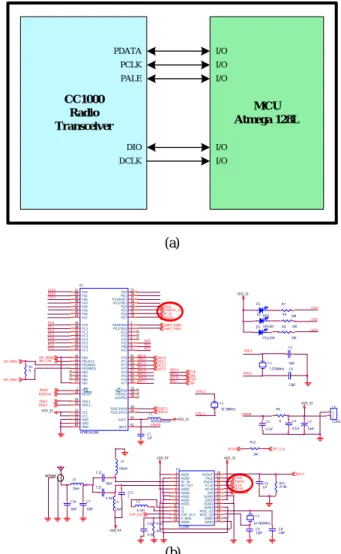
Figure 3 (a) shows the CC1000 RF wireless transceiverinterfacing with a micro-controller. The schematic of RF transceiver interface as shown in Figure 3 (b). The CC1000 RF wireless transceiver chip is configured using a three-wire bus, comprising of PCLK, PDATA and PALE signals. Data interfacing is done via the DCLK and DIO pins of the microcontroller. The DIO and DCLK pins can be used for connecting the RF transceiver to a UART.
Figure 2 shows the block diagram of the designed sensor network platform, consisting of five major modules: embedded micro-controller, Radio Frequency (RF) transceiver, power management, I/O expansion, and serial communication (RS-232).
The main micro-controller is an Atmel ATmega128L or ATmega128 running at 8MHz and delivering about million instructions per second (MIPS). [5] This 8-bit micro-controller has 128KB flash program memory, 4KB static RAM, 10-bit analog-to-digital converter, four hardware timers, 53 general-purpose I/O lines, two external universal asynchronous receiver transmitter (UART) and one serial peripheral interface (SPI) port. The radio Transceiver module consists of a CC1000 RF wireless transceiver (Chipcon Ltd., Norway), operates in the ISM band at 433MHz or 916MHz with a maximum data rate of 76.8kbps and has three LED’s for output. At active mode, the hardware consumes 33mA. In sleep mode, the system draws only 30uA of current, enabling the battery to last for more than a year. Also, the indoor radio range is approximately 20-30m. When many sensors have to communicate with the controller, standard communication interfaces such as Serial Peripheral Interface (SPI) or
Integrated Circuit (I2C) allow sharing a single communication
bus. The I/O subsystem interface consists of I/O expansion connector that we designed to interface with a variety of sensing and programming boards.
CC1000 Radio Transceiver MCU Atmega 128L PDATA PCLK PALE DIO DCLK I/O I/O I/O I/O I/O (a)
The expansion connector can also be used to program the device and to communicate with other devices, such as a PC serving as a gateway node. Additionally, it contains a standard UART (RS-232) interface to control or provide data to any UART protocol based device. In power battery part, battery system of the micro-controller (ATmega128L) and radio transceiver requiring 3V. The micro-controller has been optimized for low-power, battery operated systems.
PC CPU ATmega 128L UART MAX232 Rx Tx Transmission Control CC1000 Radio Trasceiver Power Battery External Power Supply
I/O Expansion Connector
3V
Fig. 2 Block diagram of a fabricated sensor network platform.
XTAL2 R7 330 R10 82K D3 Y ELLOW SPI_CLK C9 13pF LED3 C10 4.7pF LED3 ADC3 VDD_33 ADC3 C3 0.1uF SPI_MISO CHP_OUT ADC0 UART_TXD0 SPI_MOSI PCLK PC6 LED2 L3 10uH ADC4 PDATA XTAL2 ADC1 ADC2 PALE ADC7 C15 1nF TOSC2 R9 330 ADC0 VDD VSNSR _33 C13 4.7pF UART_RXD0 VDD_RF DCLK LED2 INT3 CC1000 U1 24 3 4 5 6 2 7 8 9 10 11 12 13 14 15 16 17 18 19 25 26 27 1 20 21 22 23 28 DCLK RF_IN RF_OUT AVDD AGND AGND AGND AGND AVDD L1 L2 CHP_OUT R_BIAS AGND AVDD AGND XOSC_Q2 XOSC_Q1 AGND PCLK PDATA PALE AVDD DGND DVD0 DGNDDIO RSSI/IF Y 2 32.768KHz R1 R C11 C PC3 RESET# C7 10pF VDD_33 ADC2 SPI_MISO D1 RED PC1 C14 10pF PCLK PC4 SPI_MODE PDATA VSNSR C12 10pF C1 1uF C5 13pF PC0 INT2 Y 1 7.3728MHz ANTENNA PC2 ADC5 TDI XTAL1 C8 13pF ADC7 R12 10K C2 10uF TMS ADC5 INT1 VDD_33 TOSC1 ADC6 U1 ATMEGA128/L 49 1 50 17 51 3 52 2 53 18 54 19 55 4 56 20 57 5 58 21 59 6 60 22 61 7 62 23 63 8 64 24 9 25 10 26 11 27 12 28 13 29 14 30 15 31 16 32 33 34 35 36 37 38 39 40 41 42 43 44 45 46 47 48PA2 PEN PA1 PB7 PA0 PE1/TXD0 VCC PE0/RXD0 GND TOSC2/PG3 PF7 TOSC1/PG4 PF6 PE2 PF5 RESET PF4 PE3 PF3 VCC PF2 PE4 PF1 GND PF0 PE5 AREF XTAL2 GND PE6 AVCC XTAL1 PE7 PD0 PB0 PD1 PB1/SCK PD2/RXD1 PB2/MOSI PD3/TXD1 PB3/MISO PD4 PB4 PD5 PB5 PD6 PB6 PD7 WR/PG0 RD/PG1 PC0 PC1 PC2 PC3 PC4 PC5 PC6 PC7 ALE/PG2 PA7 PA6 PA5 PA4 PA3 TDO ADC0 Y 3 14.7456MHz ADC4 VDD_RF PC5 TOSC1 TCK DCLK R11 27.4K D2 GREEN USART1_CLK LED1 R8 330 R6 R J3 CON2 1 2 PALE ADC1 C4 0.1uF SPI_CLK L1 BLM10A221SG L2 4.7nH XTAL1 ADC6 PC7 LED1 C6 13pF L5 10uH TOSC2 PEN# L4 120nH VDD_33 (b)
Fig. 3 Interface connection between a transceiver and a MCU. (a) RF transceiver interface with MCU.
(b) The schematic of RF transceiver interface.
3. SYSTEM TEST
Figure 4 shows the fabricated board of wireless transceiver board. As the sensor node is to be carried by the person, the microcontroller used in the setup is about 1.4in ×1.4in in size, and RF Transceiver module is lesser than 1in×1in, resulting in the total size of the board is approximately 2.9in × 2.9in. As a RF transceiver for wireless sensor networking, CC1000 RF wireless transceiver can be used as shown in Figure 2. The
ICCAS2005 June 2-5, KINTEX, Gyeonggi-Do, Korea
commercialized UHF data transceiver module chips (CC1000, Chipcon Ltd,. Norway) were integrated in single chip. In contrast, at optimum input supply voltage, the CC1000 RF wireless transceiver consumes 14.8mA to transmit at 3mW and consumes 5.3mA to have a receive sensitivity of -20dBm.
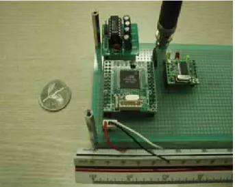
Fig. 4 Fabricated wireless transceiver board.
Fig. 5 Test system for the fabricated transceiver board. When transmitting at the same, the CC1000 RF wireless transceiver consumes 12mA. In practice RF transceiver provides an outdoor, line-of-site communication range of up to 300 feet compared to 900 feet for the RF transceiver. The RF transceiver offer transmission data rates of approximately 76.8Kbps.
Figure 5 shows test system for the fabricated transceiver board for wireless sensor networking. The fabricated board consists of three parts. The First parts consists of a micro-controller, the second part consists of a RF transceiver from control signal of the microcontroller. The third part consists of a UART (RS-232) serial communication to other
device. The sensor node was tested successfully to obtain the required RF signal from the micro-controller and RF transmitter. This part of the sensor nodes and base station was able to communicate in the range of 30~100m.
Fig. 6 Data packet of the RF transceiver.
4. EXPERIMENTAL RESULTS
A low power sensor platform and sensor node was designed and fabricated for ubiquitous health care system. A sensor network monitors continuously patients under their natural physiological states. In this paper, we describe wireless sensor network architecture consisted of sensor nodes, RF transceiver. Also, in this paper, sensor network platform for health care has been designed, fabricated and tested. The design of a series of platforms for sensing, processing, communication and power has been described. The First parts consists of a micro-controller, the second part consists of a RF transceiver from control signal of the microcontroller. The third part consists of a UART (RS-232) serial communication to other device. The sensor node was tested successfully to obtain the required RF signal from the microcontroller and RF transmitter. We also optimized the sensor node in the view point of system simplification, small system size, and low operating power.
REFERENCES
[1] I.F. Akyildiz et al., “Wireless Sensor Networks: A
Survey,” Computer Networks, vol. 38, 2002, pp. 393-422.
[2] C. Shen, C. Srisathapornphat, and C. Jaikaeo, “Sensor
Information Networking Architecture and Applications,” IEEE Pers. Commun., Aug. 2001, pp. 52–59.
[3] G. J. Pottie and W. J. Kaiser, “Wireless Integrated
Network Sensors,” Commun. ACM, vol. 43, no. 5, May 2000, pp. 551-58.
[4] Asada, G., Dong, M., Lin, T., Newberg, F., Pottie, G.,
ICCAS2005 June 2-5, KINTEX, Gyeonggi-Do, Korea
Marcy, H., and Kaiser, W. Wireless integrated network sensors: Low-power systems on a chip. In Proceedings of the 24th IEEE European Solid-State Circuits Conference (Den Hague, The Netherlands, Sept. 21–25). Elsevier, 1998, 9–12.
[5] J. Hill, System Architecture for Networked Sensors,
doctoral thesis, Dept. of Computer Science, Univ. of California, Berkeley, 2003.
[6] Dong, M., Yung, G., and Kaiser, W. Low-power signal
processing architectures for network micro sensors. In Proceedings of the 1997 International Symposium on Low-Power Electronics and Design (Monterey, Calif., Aug. 18–20). IEEE, New York, 1997, 173–177.