High Performance PI Current Controller for
a Switched Reluctance Motor
A. Ashoornejad *, A. Rashidi *, S. M. Saghaeian-nejad *, and Jin-Woo Ahn
**
Abstract
– The most common current controller for the Switched Reluctance Motor (SRM)is the hysteresis controller. This method, however, suffers from such drawbacks as variable switching frequency, consequent audible noise and high current ripple. These disadvantages make this controlling method undesirable for many applications. The alternative solution is the PI controller. Since the fixed gain PI current controller can only be optimized for one operating point, and on the other hand, SR motor is highly nonlinear, PI controller gain should be adjusted according to incremental inductance. This paper presents a novel method for PI current controller gain adaptation which is simple and yields a good performance. The proposed controller has been implemented on a test bench using a eZdsp F28335 board. The
performance of the current controller has been
investigated
in both simulation andexperimental tests using a four-phase 8/6 4KW SRM drive system.
Keywords:
Switched reluctance motor, Current control, Instructions, PI controller, Back-emf1. Introduction
The SRMs drive has many advantages such as rugged construction, high torque and high efficiency, low cost, etc. because of this advantages, this motor have attracted many researches, especially at last two decade. One of the primary disadvantages of the SRM is the high torque ripple. The torque is often controlled based on nonlinear relation between torque and current, via an inner current loop. To achieve torque with low ripple, current controller must have high performance and follow the reference current appropriately. The most common current controller for SRM drive is the hysteresis controller which has proved stable performance for non-linear applications, as is the case for SRMs. There are, however, a few disadvantages such as variable switching frequency and high current ripples. PI controller, on the other hand, has several advantages such as fixed switching frequency, low current ripple and ease of digital implementation. Therefore, it can be used in SRM current control loop. However, using this controller for highly nonlinear systems has some problems. PI controller is usually adjusted for a specified operating
point and the responses at other operating points tend to be over or under the designed bandwidth. To overcome these problems in SRMs current controller, gain adaptation PI with back-emf decoupling can be used. Gain adaptation of the controller is based on machine characteristics. In [1], a simple linear adaptation was used to adjust the current controller PI gains. This method has the advantage of being simple. The variations of the bandwidth and the phase margin are limited but still exist. In [11] it is assumed that incremental inductance is a linear function of position and saturation effect is not considered. So this method is not valid in nonlinear operating region. In [13], the inductance and back-emf are calculated by complicated equations. This method needs considerable processing time. In this paper, a new method of gain adaptation for PI current controller is proposed. The proposed method needs fewer calculations and yields a good performance. This paper is organized as follows: in section 2 the model of machine and design of current controller for an 8/6 SRM is described. Based on gain adaptation methods, in section 3 the proposed gain adaptation for PI current controller is presented. Simulation and experimental results are presented to verify the performance and viability of the proposed method.
2. Machine Modeling and Controller Design
Design of current controller is based on machine characteristics. These characteristics are usually obtained
* Dept. of Electrical and Computer Engineering of Isfahan University of Technology, Iran. ([email protected], [email protected]. ac.ir, [email protected])
** Dept. of Mechatronics Engineering, Kyungsung University, Korea. ([email protected])
from experimental measurements or from numerical calculations such as finite element analysis. The proposed controller is designed for a four phases 8/6 SRM whose parameters are listed in the Table 1.
Table 1. Machine Characteristics
8 Number of stator poles
6 Number of rotor poles
1500 rpm Nominal speed 5.5 hp Nominal power 0.7 Ω Phase Resistance 280 V Nominal voltage 2.1 SRM Modeling
SRM is usually designed so that mutual effects of phases get minimal. Therefore, neglecting mutual inductances, the electrical phase equation is:
, , , ph ph s ph ph ph s ph s ph d i V R i dt i di R i L i dt
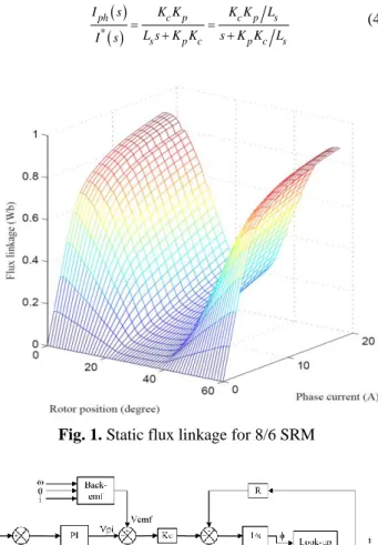
(1)where, Vph is the applied phase voltage, Rsis the winding resistance, iph the phase current, φ the flux linkage, Ls the incremental inductance, θ the rotor position and ω is the motor speed. The last expression in the right hand of above equation is back-emf. Incremental inductance is obtained by dψ(θ, iph)/di. Fig. 1 shows flux linkage characteristics of a 8/6 SRM over one electrical period. As shown in the figure, the SRM is highly nonlinear and motors flux is a function of both rotor position and phase current. The incremental inductance and back-emf can be obtained numerically using flux characteristics and then be used in motor current control.
2.2 Back-emf Decoupling
The first step in achieving a high-performance current controller is to decouple the back-EMF term. The back-emf can be assumed as a disturbance to the current loop. Therefore, decoupling back-emf can be done by adding it to output of PI controller, as shown in Fig. 2.
2.3 PI Controller Gain Adaptation
If back-emf is completely decoupled, the current loop of the SRM can be simplified as shown in Fig. 3. The open
loop transfer function of Fig. 3 is:
p
i p
ph c err s s s K s K K I s K I s s L s R L (2)The controller can be adjusted so that machine pole be eliminated. In other words:
i s
p s
K R
K L (3)
By substituting (3) in (2), the closed loop transfer function of system is:
* ph c p c p s s p c p c s I s K K K K L L s K K s K K L I s (4)Fig. 1. Static flux linkage for 8/6 SRM
Fig. 2. Block diagram of PI controller with back-emf
decoupling
In the above equation, the term of KpKc/Ls is bandwidth of the closed loop system in which Kc is the gain of the power converter. As mentioned before, the incremental inductance is a nonlinear function of position and current and varies significantly within one electrical cycle. Therefore, the integral and proportional gains to achieve the same bandwidth for overall operating point are:
s b p c s b i c L K K R K K (5)
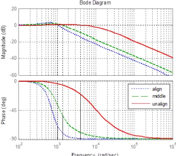
The proportional gain of current controller varies according to incremental inductance and the integral gain is constant. The Bode diagram of the closed loop system when no adaptation is used is depicted in Fig. 4. The diagram is plotted for three states of aligned, unaligned and intermediate positions. As it can be seen in the figure, the magnitude of the closed loop system varies widely with regard to the operating point and thus results in variation of bandwidth and phase margin. Therefore it seems gain adaptation is necessary to achieve a proper current response and fixed bandwidth for overall operating point.
Fig. 4. Bode diagram of closed loop system when no
adaptation is used
3. Proposed Method for Gain Adaptation
Rahman and Schulz [1] used a linear method for PI controller gain adaptation. In their proposed method,
inductance curves are approximated with simple linear equations. Variations of bandwidth and phase margin are reduced but still exist, especially at low currents where approximations have no accuracy. Another method is gain adaptation according to the precise magnitude of incremental inductance. In [6] the incremental inductance is stored in a two dimensional look-up table. However, the look-up table approach requires memory and valuable processing time. In [13] the incremental inductance is obtained from complicated equations.
According to (4), to have an appropriate performance, only proportional gain need to be adapted. So in this paper, the proportional gain is adapted according to the following equation:
p current position p nom
K K K K (6)
in which Kp osition and Kcurrent are position and current adaptation coefficients, respectively. Also Kp - n o m is the nominal proportional gain, which is set to 6 Amperes in this paper at intermediate position according to (5). Fig. 5 shows the gain adaptation for position Kp o s i t i o n. Motor inductance versus position for constant current (6 A) are shown in this figure. The equation which approximated this curve is: 0.012 30 36 0.012 0.0028 ( 36) 36 46 0.043 0.013 sin( * 11 47 11) 46 58 0.043 58 60 position K (7)
Fig. 6 shows the gain adaptation for current, Kcurrent. Also motor inductance versus current at intermediate position (45 degree) is shown in this figure. The equation which approximated this curve is:
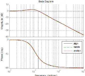
0.018 0.05 cos 13 1.5 13 0 8 0.015 8 18 current K i i i (8)It should be noted that since Kposition and Kcurrent gains are set to 6 Amperes and 45 degree, there is no adaptation needed for this point. So it is necessary to use a coefficient for these curves. Fig. 7 shows the bode diagram of the closed loop system, when gain is adapted according to the proposed method. As can be seen in the figure, the bandwidth and phase margin variations are limited very well.
Fig. 5. Phase inductance versus position at 6 Ampere, and
the gain adaptation for position.
Fig. 6. Phase inductance versus current at middle position
(45 degree), and the gain adaptation for current.
Fig. 7. Bode diagram of current loop system with gain
adaptation
4. Simulation and Experimental Results
4.1 Simulation Results
To verify the performance of the proposed controller, simulation results are presented in this section. Simulation tests have been carried out using MATLAB/Simulink.
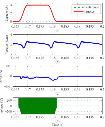
Fig. 8 shows simulation results for fixed gain PI controller. Reference and motor phase current are shown in Fig. 8 (a). Difference between these two currents is plotted in Fig. 8 (c). Also the motor torque and phase voltage are shown in this figure. As shown in the figure, the fixed gain PI controller has a different bandwidth at different operating point and where the reference current is constant; the current error is not zero. Maximum current error for this controller is equal to 0.008 Ampere.
Fig. 8. Simulation results for fixed gain PI controller,
150rpm, 3N.m
Fig. 9 shows simulation results for linear gain adaptation PI controller. As shown in the figure, linear gain adaptation method has improved the performance, compared to fixed gain PI controller. The maximum error in this case is 0.004 ampere.
Also the simulation results for PI gain adaptation according to exactly incremental inductance (PIGS) are shown in Fig. 10. As shown in Fig. 10, the current error has a variation between 0.003 and -0.003 Ampere band and the amplitude of error is constant for minimum and maximum
of inductance. Moreover, where the variation of reference current is equal to zero, the magnitude of error is very small, close to zero.
Fig. 9. Simulation results for linear gain adaptation PI
controller, 150rpm, and 3N.m.
Fig. 10. Simulation results for exactly gain adaptation PI
controller, 150rpm, and 3N.m.
Finally, the performance of the proposed controller is shown in Fig. 11. This figure shows that the performance of proposed controller is similar to pigs controller and the error has same amplitude. To achieve a comparison between PI current controllers for SRM drive, the results for controllers are summary in Table 2. The torque ripple (Kr) is calculated by follow equation:
max min 100 r ave T T K T (9)
where Tmax, Tmin and Tave are the maximum, minimum and average of total torque, respectively. As shown in the Table 2, compare to other PI controller, the proposed controller has better and improved performance.
Fig. 11. Simulation results for proposed gain adaptation PI
controller, 150rpm, and 3N.m.
Table 2. Comparison of PI Controllers
PI Linear PIGS proposed Bandwidth
variation wide limited
No variation Teeny Lookup table - 1 2 1 Max error(A) 0.008 0.004 0.003 0.003 Torque ripple (%) 23.05 22.70 22.50 22.55
4.2 Experimental Results
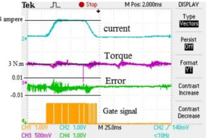
The proposed SRM current controller has been tested experimentally. The proposed controller has been implemented on a test bench using a eZdsp F28335 board shown in Fig. 12. Phase currents are measured using a Hall effect current sensor. Angular velocity and rotor position are detected by means of encoder. The tests performed in simulation have been repeated experimentally. Experimental results for the fixed gain PI, Linear gain adaptation PI and proposed PI current controller are shown in Figs. 13 to 15, respectively. These figures are very close to the simulation results shown in Figs.8, 9 and 11. As can be seen in these figures, proposed controller has improved steady and dynamic performance compared to the conventional PI current controllers.
Fig. 12. Experimental test bench.
Fig. 13. Experimental result for fixed gain PI controller,
150rpm and 3N.m.
5. Conclusion
An adaptive PI current controller for SRM drives was developed and a back-EMF decoupling and an adaptive PI
Fig. 14. Experimental result for Linear gain adaptation PI
controller, 150rpm, 3N.m.
Fig. 15. The caption for a figure must follow the figure
controller were used for current loop. The proposed current controller adapts the PI gains in a simple way. Moreover, it not only limited the variations of current loop bandwidth but also improved the steady state and dynamic performance of the controller. Simulation and experimental results were also used to confirm the better performance of the proposed controller.
References
[1] S. E. Schulz and K. M. Rahman, “High performance digital PI current regulator for EV switched reluctance motor drives,” Industry Applications Conference, 2002. Proceeding in the 37th IAS Annual Meeting, vol.3, pp. 1617-1624 vol.3, 13-18 Oct. 2002.
[2] Ching-Guo Chen and Tian-Hua Liu; , “Nonlinear controller design for switched reluctance drive systems,” IEEE Transactions on Aerospace and Electronic Systems, vol.39, no.4, pp. 1429-1440, Oct. 2003.
[3] Z. Lin, D. Reay, B. Williams and X. He, “High-performance current control for switched reluctance motors based on on-line estimated parameters,” IET Electric Power Applications, vol.4, no.1, pp.67-74, January 2010 doi: 10.1049/iet-epa.2009.0016.
[4] H. Hannoun, M. Hilairet and C. Marchand, “Design of an SRM Speed Control Strategy for a Wide Range of Operating Speeds,” IEEE Transactions on Industrial Electronics, vol.57, no.9, pp. 2911-2921, Sept. 2010.
[5] Yuefeng Yang, and Yihuang Zhang, “Sliding mode-PI control of switched reluctance motor drives for EV,” Proceedings of the Eighth International Conference on Electrical Machines and Systems (ICEMS 2005), vol.1, pp. 603- 607, Sept. 2005. [6] H. Hannoun, M. Hilairet and C. Marchand, “Gain-scheduling
PI current controller for a Switched Reluctance Motor,” IEEE Proceeding in International Symposium on Industrial Electronics (ISIE 2007), pp. 1177-1182, 4-7 June 2007. [7] X. Rain, M. Hilairet and O.Bethoux, “Comparative study of
various current controllers for the switched reluctance machine,” IEEE Vehicle Power and Propulsion Conference (VPPC 2010), pp. 1-6, 1-3 Sept. 2010.
[8] E. Daryabeigi, A. Emanian, M. M. Namazi, A. Rashidi and S. M. Saghaian Nejad, “Torque ripple reduction of switched reluctance motor (SRM) drives, with emotional controller (BELBIC),” Twenty-Seventh Annual Applied Power Electronics Conference and Exposition (APEC 2012), pp. 1528-1535, 5-9 Feb. 2012.
[9] M. M. N. Isfahani, S. M. Saghaian-Nejad, A. Rashidi and H. A. Zarchi, “Passivity-based adaptive sliding Mode speed control of switched reluctance motor drive considering torque ripple reduction,” IEEE International Electric Machines. & Drives Conference (IEMDC 2011), pp.1480-1485, 15-18 May 2011.
[10] Karl Johan Astrm, Richard M. Murray, “Feedback Systems,” An Introduction for Scientists and Engineers, PRINCETON UNIVERSITY PRESS , March 2010.
[11] H. K. Bae, R. Krishnan, “A study of current controllers and development of a novel current controller for high performance SRM drives,” Proceeding in Thirty-First IAS Annual Meeting, pp.68-75 vol.1, 6-10 Oct 1996.
[12] R. Krishnan, “Switched Reluctance Motor Drive: Modeling, simulation, Analysis, Design and application,” Magna Physics Publishing, 2001.
[13] H. Hannoun, M. Hilairet, and C. Marchand, “Analytical modeling of switched reluctance machines including saturation,” IEEE International Electric Machines & Drives Conference, (IEMDC ’07), vol.1, pp. 564-568, 3-5 May 2007.
A. Ashoornejadwas born in Mashhad, Iran. He received his M.S. in Electrical Engineering from the Isfahan University of Technology, Isfahan, Iran. His research interests include electric motor drives.
A. Rashidi was born in Mashhad, Iran, in 1984. He is currently Ph.D. student at Isfahan University of Technology, Isfahan, Iran. His research interests include electric motor drives, power electronics and DSP-based control systems.
S.M. Saghaeian-nejadwas born in Isfahan,
Iran, in 1952. He received his B.A., M.S. and Ph.D. in Electrical Engineering from the University of Kentucky, U.S.A. in 1977, 1979 and 1989, respectively. Since 1979, he has been with the Department of Electrical and Computer Engineering of Isfahan University of Technology, as a faculty member, where he is currently a Professor. His research interests are in the areas of electrical machines, power electronics and drives.
Jin-Woo Ahnwas born in Busan, Korea, in
1958. He received the B.S., M.S., and Ph.D. degrees in electrical engineering from Pusan National University, Busan, Korea, in 1984, 1986, and 1992, respectively.
He has been with Kyungsung University, Busan, Korea as a Professor in the Department of Electrical and Mechatronics Engineering, Kyungsung University, Busan. He was a Visiting Professor in the Department of Electrical Engineering since 1992. He has been the Director of the Smart Mechatronics Advanced Research and Technology Institute since 2008. He is the author of five books, including SRM and more than 130 research papers and has more than 30 patents. His current research interests are advanced motor drive systems and electric vehicle drives.