ETRI Journal. 2020;42(6):859–871. wileyonlinelibrary.com/journal/etrij
|
8591
|
INTRODUCTION
The orthogonal frequency-division multiplexing (OFDM) transmission scheme has a distinct advantage in that trans-mission can be made secure by effectively estimating and correcting a multipath channel. However, as the envelope function is a square wave [1], the spectrum is spread and the out-of-band power is leaked to adjacent channels [2].
Windowing in the time domain has been studied to sup-press spectral sidelobes [3]. However, a guard interval is added to the OFDM symbol to smooth the transition be-tween consecutive symbols, thereby reducing transmission throughput. The general restraints on the spectral precod-ing of zero-paddprecod-ing-OFDM and cyclic prefix (CP)-OFDM have been discovered, and block-division CP-OFDM, which
facilitates the design of a precoder with spectral efficiency, has been proposed based on these techniques [4]. In addi-tion, a technique has been proposed that includes a no-guard-OFDM scheme with no guard interval inserted. This is then combined with a spectrally compact precoder, as it avoids spreading of the spectrum [5]. To improve spectral effi-ciency, pilot patterns were designed to optimize the channel estimation of multipath channels and suppress spectral sid-elobes in a system that processes data and pilot waveforms individually to provide spectral compactness [6]. It is nec-essary to create subcarriers for transmitting the pilot sym-bols separately from the subcarriers that transmit the data symbols because the pilot subcarrier and data subcarrier may have many common frequency components. Emission suppression was first treated as a problem of minimizing O R I G I N A L A R T I C L E
Spectral encapsulation of OFDM systems based on
orthogonalization for short packet transmission
Myungsup Kim
1|
Do Young Kwak
1|
Ki-Man Kim
2|
Wan-Jin Kim
3This is an Open Access article distributed under the term of Korea Open Government License (KOGL) Type 4: Source Indication + Commercial Use Prohibition + Change Prohibition (http://www.kogl.or.kr/info/licenseTypeEn.do).
1225-6463/$ © 2020 ETRI
1Department of Mathematical Sciences,
Korea Advanced Institute of Science and Technology, Daejeon, Rep. of Korea
2Department of Radio Communication
Engineering, Korea Ocean and Maritime University, Busan, Rep. of Korea
3Agency for Defense Development,
Changwon, Rep. of Korea
Correspondence
Myungsup Kim, Department of Mathematical Sciences, Korea Advanced Institute of Science and Technology, Daejeon, Rep. of Korea.
Email: [email protected]
Funding information
This work was supported by the Agency for Defense Development, Republic of Korea under Grant UD170022DD.
A spectrally encapsulated (SE) orthogonal frequency-division multiplexing (OFDM) precoding scheme for wireless short packet transmission, which can suppress the out-of-band emission (OoBE) while maintaining the advantage of the cyclic prefix (CP)-OFDM, is proposed. The SE-OFDM symbol consists of a prefix, an inverse fast Fourier transform (IFFT) symbol, and a suffix generated by the head, center, and tail matrices, respectively. The prefix and suffix play the roles of a guard interval and suppress the OoBE, and the IFFT symbol has the same size as the discrete Fourier transform symbol in the CP-OFDM symbol and serves as an information field. Specifically, as the center matrix generating the IFFT symbol is orthogonal, data and pilot symbols can be allocated to any subcarrier without distinction. Even if the proposed precoder is required to generate OFDM symbols with spectral efficiency in the transmitter, a corresponding decoder is not required in the receiver. The proposed scheme is compared with CP-OFDM in terms of spectrum, OoBE, and bit-error rate.
K E Y W O R D S
the Frobenius norm of the matrix, and then an orthogonal precoding scheme was developed based on singular value decomposition (SVD) to obtain significant performance [7]. To eliminate the discontinuity between consecutive OFDM symbols, the relationship between the previous symbol and the current symbol was derived in the form of a matrix equation through the N-th differentiation, and a method of reducing the out-of-band emission (OoBE) by updating the data vector and specific gravity vector was proposed [8]. As this method has a cyclic structure and a concatenation error may occur, it is disadvantageous in that it cannot be applied to the burst mode communication method. To reduce jointly the OoBE and peak-to-average power ratio of the OFDM-based system, a method called alignment suppression, which generates a suppression signal, has been proposed [9]. As this method utilizes the original redundant CP in the OFDM symbol, it does not reduce transmission efficiency. It is also possible to perform demodulation similar to legacy OFDM without changing the receiver structure. However, as the transmitter uses the channel state information (CSI), a secure channel is required in the reverse direction, and the receiver has complexity in calculation for the extraction of CSI from the received signal. In addition, the suppression signal may be leaked to the data owing to the incomplete channel information, and there may be a deterioration of the bit-error rate (BER) performance and a decrease in the synchronization performance owing to the change in the CP. In filter bank multicarrier (FBMC) which is a filtered multi-carrier system, subcarriers are individually shaped to reduce OoBE [10]. Usually, as the subcarriers have a length of four times the symbol length, this method is not suitable for the future requirements of high transmission efficiency with short delay. A multicarrier modulation scheme called generalized frequency-division multiplexing (GFDM) has been proposed [11], which includes the case of CP-OFDM and single-carrier frequency-domain equalization. However, with the exception of these special cases, subcarrier fil-tering results in non-orthogonality between subcarriers. Consequently, intersymbol interference (ISI) and intercar-rier interference occur, and hence, to eliminate them, the complexity of the receiver increases. A filtered (F)-OFDM scheme that limits OoBE by filtering OFDM symbols has been proposed [12]. However, when applied to short-length OFDM symbols, the F-OFDM scheme results in ISI/ inter-channel interference (ICI) and can affect synchronization and BER performance because it allows the length of the filter to be half the length of the OFDM symbol. A scheme has been proposed in which a transmitter reduces OoBE by combining existing OFDM and cancellation carriers, and a receiver can perform demodulation in the same manner as an existing OFDM demodulation scheme [13]. This ap-proach generalized and unified existing active interference cancellation and time-domain OoBE suppression schemes.
This method was also shown to satisfy the spectral mask specified in the EN-50560 standard. The method greatly improved the spectral characteristics compared with the previous methods [14‒16]. Compared with the raised co-sine pulse method, the proposed method improves the data carrier loss from 28% to <4%.
In this study, we propose a precoding scheme that main-tains the merits of CP-OFDM and can solve the problem of OoBE. The proposed scheme provides high blocking char-acteristics by forming spectral nulls at the upper and lower boundaries of the signal band. Numerous existing schemes, such as channel and frequency offset estimations in CP-OFDM, can be applied to the proposed scheme. As the pro-posed precoding scheme has no effect on the inverse fast Fourier transform (IFFT) symbol and is compatible with the legacy OFDM scheme, the pilot symbol can be transmitted without any sacrifice. Therefore, the proposed scheme has no self-interference between subcarriers and has the same BER performance as CP-OFDM.
The rest of this paper is organized as follows. Section 2 describes the baseband communication model with the pro-posed precoding scheme to develop and verify the propro-posed scheme. Section 3 describes the precoder matrix generation process and the approximation of the generated precoder. The pilot insertion scheme is considered in the proposed scheme. Section 4 provides an example of precoder matrix generation with the short OFDM symbol defined in IEEE 802.11a [17] and the precoding structure defined in IEEE 802.11g [18], and analyzes its frequency response charac-teristic. In Section 5, the BER performance of the proposed scheme in additive white Gaussian noise (AWGN) and mul-tipath fading channel environments is measured and com-pared with that of CP-OFDM. Section 6 summarizes the results of this study and suggests applicable communication fields.
2
|
COMMUNICATION MODEL
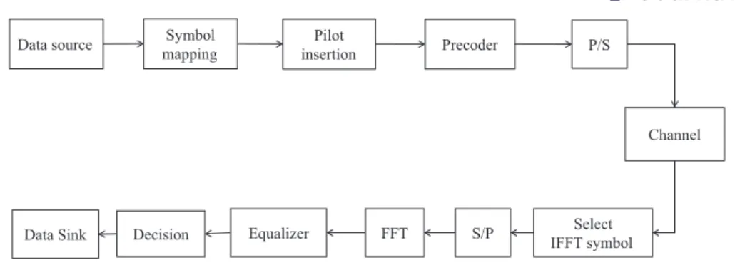
The communication system model using the proposed precoding scheme is shown in Figure 1. The data source generates binary data and is mapped to a quadrature ampli-tude modulation (QAM) symbol using a symbol mapper. Through the pilot insertion block, the pilot symbols can be transmitted at locations based on a predetermined rule. The precoder converts an input vector into an OFDM symbol, which consists of a prefix, an IFFT symbol, and a suffix. The P/S converter converts the parallel OFDM symbol to the serial sample sequence. The channel is modeled as an AWGN and multipath fading channel. The Select IFFT symbol selects the IFFT symbol in the received OFDM symbol. The S/P converts the serial sample sequence into a parallel vector. The FFT transforms the input vector from
the time domain to the frequency domain. The equalizer block can extract the pilot symbols and perform equaliza-tion. The decision block decides the input samples as QAM symbols, converts them into binary data, and sends them to the sink block. As in CP-OFDM, the feature of this model is that there is no decoder in the receiver corresponding to the precoder in the transmitter because the IFFT symbol carrying the data symbols is not changed by the precoder.
3
|
PRECODER MATRIX
GENERATION PROCESS
The process of generating a precoder through six functional blocks is shown in Figure 2. The precoder matrix is generated by using the carrier matrix used in CP-OFDM as a mapping matrix, converting the matrix into the time domain, adding a prefix and suffix, weighting, zero insertion, and orthogonali-zation. The orthogonalization involves orthogonalizing the matrix such that the subcarriers transmitting the data sym-bols are orthogonal to one another. Similar to CP-OFDM, the precoder performs almost the same function as converting the input data symbol to the time domain through the inverse discrete Fourier transform (IDFT).
3.1
|
Mapping matrix
J
The arrangement of the OFDM subcarriers in the frequency domain can be represented by the following general matrix:
where N and M are the FFT size and the number of data sym-bols, respectively [19,20]. The zero matrices are the direct cur-rent (DC) subcarrier
the positive and negative identity matrices
and the zero guard matrix.
(1) J�∈ ℝN×M�= ⎡ ⎢ ⎢ ⎢ ⎢ ⎣ 0dc I+ 0g I− ⎤ ⎥ ⎥ ⎥ ⎥ ⎦ , (2) 0dc= 0 ( 1×M2 ) , (3) I+= I−= IM 2 = diag ([⏞⏞⏞⏞⏞⏞⏞⏞⏞⏞⏞⏞⏞⏞⏞⏞⏞⏞⏞⏞⏞M∕2 1, 1, ⋯ , 1 ]) , (4) 0g= 0 ( 𝛽×M2 ) , FIGURE 1 Communication system model
Data source
Data Sink Equalizer Select
IFFT symbol Channel FFT S/P Precoder Pilot insertion Symbol mapping P/S Decision
and all spaces are zero. When the parameter β = 0, there is no guard subcarrier.
3.2
|
Transformation of the mapping matrix
to the time domain
Each column of the mapping matrix can be converted from the frequency domain to the time domain by obtaining the N-point IDFT as.
where P∈ ℂN×M and F
N∈ ℂN×M is the discrete Fourier
trans-form (DFT) matrix
As the matrix P is orthogonal, it can be expressed using a matrix A∈ ℂN×M as
The matrix A can be decomposed by SVD as
where U and V are unitary matrices and 𝚺 =
[ S 0
]
. The matrix
is a diagonal matrix with eigenvalues and 0∈ R((N−M)×M) is a zero matrix. From Appendix A, we have
where K∈ ℝ(N×M)=[ IM
0 ]
. This result indicates that P can be represented by the product of two unitary matrices and an iden-tity matrix, and the orthogonality can be verified by
PHP= VKHUHUKVH= VKHKVH= VVH= IM. It can be
ob-served that a matrix that is orthogonal in the frequency domain is also orthogonal in the time domain.
3.3
|
Permutation matrix
E
pThe matrix P can be represented with three block matrices
where Pb∈ ℂLb×M, P
m∈ ℂ(N−Lb−Le)×M, and Pe∈ ℂLe×M. Copying
the Pb block matrix and attaching it below Pe, and copying the Pe block matrix and placing it in front of Pb yields an extended
OFDM subcarrier matrix
where Q∈ ℂ(N+Lb+Le)×M and E
p is a permutation matrix
where Ep∈ ℝ(Lb+N+Le)×(Lb+N+Le).
3.4
|
Weighting matrix W: Soft transition
in the time domain
The weighting matrix gradually increases the magnitudes of both ends of the OFDM symbol and then gradually decreases them. The reason for this is to eliminate the abrupt jump at the beginning and end of the OFDM symbol, which is the reason for the spectrum spread of the OFDM symbol. To remove the jumps, we multiply the weight function equally to each carrier of the OFDM symbol. The weighting function smoothly ramps up and down to limit spectral spreading. Therefore, it is an impor-tant function that limits the spectrum of OFDM, and it should be decided according to the specification of the system to be used.
For blocking the OoBE, the spectrum of the input signal must be limited. To do so, all the subcarriers must begin at 0 and end at 0. Multiplying Q by the weighting matrix, we have
where W is a diagonal matrix
(5) P= FHNJ, (6) FN=√1 N � e−j2𝜋mnN � −N∕2≤m, n≤N∕2−1. (7) P= A(AHA)− 1 2. (8) A= U𝚺VH, (9) S= diag( s1 s2 ⋯ sM ) (10)
P= U𝚺VH((U𝚺VH)H(U𝚺VH))−
1 2 = U [ IM 0 ] VH = UKVH, (11) P= ⎡ ⎢ ⎢ ⎢ ⎣ Pb Pm Pe ⎤ ⎥ ⎥ ⎥ ⎦ , (12) Q= EpP= ⎡ ⎢ ⎢ ⎢ ⎢ ⎢ ⎢ ⎣ Pe Pb Pm Pe Pb ⎤ ⎥ ⎥ ⎥ ⎥ ⎥ ⎥ ⎦ = ⎡ ⎢ ⎢ ⎢ ⎣ Pe P Pb ⎤ ⎥ ⎥ ⎥ ⎦ , (13) Ep= ⎡ ⎢ ⎢ ⎢ ⎣ 0 0 IL b 0 IN 0 IL e 0 0 ⎤ ⎥ ⎥ ⎥ ⎦ , (14) R= WQ = WEpP,
where 𝛋 = [𝜅1, 𝜅2, ..., 𝜅N+Lb+Le]
T is a weighting vector.
3.5
|
Zero insertion to the
bandwidth boundaries
The zero insertion at the band boundaries in the frequency domain is performed by filtering in the time domain. The weighted matrix R is filtered as
where h= [h1, h2, ..., hr+1]T is an r-th-order filter coefficient
vector in the time domain, ⊗
c denotes the convolution of the
col-umns of R and the vector h, and the size of G is L× M. Here, r is set to an even number to simplify the formulas. From Appendix B, the matrix G can be expressed in another form as
where 𝛀 is a diagonal matrix
where 𝛚 = [𝜔1, 𝜔2, ..., 𝜔L]T is a filtering coefficient vector in
the frequency domain.
3.6
|
Precoder matrix
𝚲
The matrix G can be expressed with three block matrices as
where Gh∈ ℂLp×M, G
c∈ ℂN×M, and Gt∈ ℂLs×M, where
Lp=⌊Lb+ r∕2⌋ and Ls=⌊Le+ r∕2⌋.
We define an orthogonalization function f(Gc) that
makes the center matrix Gc orthogonal, regardless of the
weighting and filtering matrices. The matrix function f(Gc)
is also multiplied to the head matrix Gh and the tail matrix Gt
to maintain the continuity of the subcarriers. The orthogonalizing matrix is defined as
where X∈ ℂM×M. For a matrix X to exist, the rank of the
ma-trix Gc must be M so that the rank of GHcGc is M. The factors
influencing the rank of Gc are determined by the weighting
and zero insertion functions. We can prevent the rank from falling below M, as it will be mentioned later. As the order of the zero insertion function is sufficient as r = 2, setting the prefix and suffix length of the weighting function one sam-ple less than the final length while maintaining the length of the center weighting function at N will never reduce the rank of Gc.
A precoder matrix is defined by multiplying the matrix
G by X as.
where 𝚲 ∈ ℂ(Lp+N+Ls)×M.
As G is multiplied by X, the rows in 𝚲 become curves
without any jumps. The matrix 𝚲 is represented with three
blocks as.
where the block matrices 𝚲h∈ ℂ
Lp×M, 𝚲
c∈ ℂN×M, and
𝚲t∈ ℂLs×M are head, center, and tail matrices, respectively. The
center matrix is
which is orthogonal because it has the same form as (8). In other words, the center matrix in the precoder, which is responsible for transmitting information, is orthogonal. In a method of transmitting information through an orthogonal matrix, when received through a multipath fading channel, orthogonality between subcarriers may be impaired, thereby preventing orthogonal reception. In such a case, each subcar-rier for transmitting each data symbol is formed from many OFDM subcarriers. When received through a multipath fad-ing channel, orthogonality is impaired between the subcar-riers, resulting in a decrease in reception performance. In other words, 𝚲Hc𝚲c= I cannot be guaranteed. Consequently,
each column vector of the orthogonal matrix that transmits the information must be composed of a single frequency to realize ideal transmission. However, as will be discussed in the next subsection, as 𝚲c is very similar to P formed with
a single frequency, the symbols transmitted by the proposed scheme are robust to the effects of the multipath fading channel. (15) W= diag (𝛋), (16) G= R ⊗ c h, (17) G= FHL𝛀FLErWEpP, (18) 𝛀 = diag (𝛚), (19) G ≡ ⎡ ⎢ ⎢ ⎢ ⎣ Gh Gc Gt ⎤ ⎥ ⎥ ⎥ ⎦ . (20) X ≡ f(Gc)=(GH cGc )−1 2, (21) 𝚲 ≡ GX , (22) 𝚲 ≡ ⎡ ⎢ ⎢ ⎢ ⎣ 𝚲h 𝚲c 𝚲t ⎤ ⎥ ⎥ ⎥ ⎦ = ⎡ ⎢ ⎢ ⎢ ⎣ Gh Gc Gt ⎤ ⎥ ⎥ ⎥ ⎦ X . (23) 𝚲c= GcX= Gc ( GHcGc)− 1 2,
3.7
|
Approximated precoder
In the previous section, we mentioned that, in the ideal transmission method, a subcarrier for transmitting infor-mation is formed with a single frequency. In this section, the proposed scheme shows that the center matrix respon-sible for information transmission is very close to the matrix P used in the OFDM system. As it is difficult to know exactly the role played by the precoder matrix given by (21), we analyze the inner blocks in more detail. From Appendix C, the center matrix can be approximated as.
and the center matrix 𝚲c can be represented approximately as
which shows that the center matrix of the precoder is close to the matrix P in which the subcarriers are formed at a sin-gle frequency in OFDM. We define an approximated pre-coder as
It can be observed that the proposed approximated pre-coding scheme is similar to CP-OFDM.
3.8
|
Pilot insertion
Pilot insertion in the transmitter is essential for channel es-timation. Therefore, the new transmission technique needs to be checked not only for spectral efficiency but also for the ability to transmit the pilot securely. The interference be-tween subcarriers in the frequency domain for pilot transmis-sion is examined.
From (25), the center matrix 𝚲c can be represented in the
frequency domain as.
which is the mapping matrix. As 𝚽c is close to J, the
interfer-ences between subcarriers in 𝚽c can be ignored. Therefore, the
pilots can be transmitted on arbitrary subcarriers, and various pilot insertion methods used in CP-OFDM can be utilized with-out any change.
4
|
GENERATION OF PRECODER
MATRIX WITH A SHORT PACKET/
SYMBOL
This section shows the process of generating a precoder ma-trix according to the IEEE 802.11a standard that specifies the OFDM symbol in the context of a detailed description of the proposed scheme. In the specification, a short OFDM symbol consists of a CP with Lcp = 16 samples and an IFFT symbol with N = 64 samples, and has a total length of L = 80 sam-ples. There is also a zero-frequency subcarrier and M = 52 occupied subcarriers. According to the specification, a pre-coder matrix with parameters r = 2, Lp = Ls =8, and LGI = 16 is generated with the same occupied carriers and OFDM symbol length as the specified OFDM.
4.1
|
Generation of a precoder matrix
This section shows the process of generating a precoder with the small OFDM symbols specified in IEEE 802.11a in a spec-trally efficient scheme. The result is to obtain an orthogonal matrix while maintaining the original center matrix and to change the prefix and suffix parts with the obtained matrix. As the center matrix approximately returns to the mapping ma-trix, the newly generated prefix and suffix should have spectral efficiency.
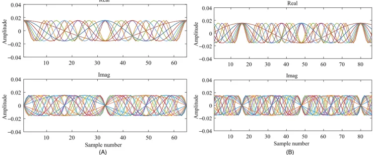
Figure 3A shows a part of a matrix P∈ ℂ(64×52)
transform-ing the frequency-domain subcarriers into the time domain, where only 16 of the 64 subcarriers are shown here for clarity of illustration. In the figure, the real and imaginary parts are symmetric and skew-symmetric, respectively, from the cen-ter. It can be observed that the subcarriers in the real part have a sudden jump at the beginning and the end, which is the main factor causing spreading of the spectrum.
Figure 3B shows the result of copying Le (= 7) samples of the front part of the IFFT symbol, attaching it after the IFFT symbol, and copying Lb + Lcp (7 + 8 = 15) samples after the IFFT symbol and placing them in front of the IFFT symbol. In this process, the original center part remains intact.
The window function is required to be symmetric and must have a value of 0 at both ends. As it is important to suppress the spread of the spectrum of the signal, the window function is preferably a smooth curve without jumps. We de-fine a weighting function as.
(24) Gc≈ FHN𝛀FNWcP (25) 𝚲c≈ P, (26) 𝚲appx= ⎡ ⎢ ⎢ ⎢ ⎣ 𝚲h P 𝚲t ⎤ ⎥ ⎥ ⎥ ⎦ . (27) 𝚽c= FN𝚲c≈ FNP= J , (28) 𝜅h(n) = x (n) , 0 ≤ n ≤ Lb− 1, (29) 𝜅c(n) = 1, 0 ≤ n < N − 1, (30) 𝜅t(n) = x ( Lb− 1 + n), 0 ≤ n < Le− 1,
where
Figure 4A is an example of a window function with a weighting vector 𝛋 with Lb = Le =7, Lcp = 8, and N = 64,
which can be used for a short OFDM symbol with 72 sam-ples. The center portion of the function is maintained flat, whereas the front and back portions of the function are grad-ually increased or gradgrad-ually decreased so that the entire curve becomes smooth
The filtering function makes the magnitudes zero at the frequency band boundaries, where the interference power is blocked from flowing into the neighboring channel. As a fil-ter function satisfying the condition, a binomial filfil-ter.
where r is the filter order, is considered. The filtering vector h in the time domain is composed of the coefficients of 𝜔(𝜃) as
The filtering vector 𝛚 in the frequency domain can be
ob-tained by sampling the function 𝜔 (𝜃).
Figure 4B shows the frequency responses of the filters ac-cording to the orders. The feature of this filter is that it can be implemented with a short filter with a small order r from the filter function given by (28), and it blocks the OoBE because 𝜔 (±𝜋) = 0.
Figure 5 shows the waveform shaped by using window and filtering functions. Figure 5A shows the result when the input matrix is multiplied by the window matrix W, where the amplitudes of the subcarriers gradually increase and de-crease in the head and tail, respectively, and the center part remains constant. Figure 5B shows the result of filtering the column of the input matrix when the order r = 2. It can be ob-served that the subcarriers are much smoother than in Figure 5A. To match the length with that specified in IEEE 802.11a, the prefix and suffix lengths of the input matrix are set to 7. If filtering by a filter of order 2 is performed, the filtering result is increased by two samples.
(31) x(s) =1 2 ( 1− cos 2𝜋 s Lb+ Le− 2 ) . (32) h(z) = 1 2r ( 1+ z− 1) r, (33) 𝜔 (𝜃) = h (z)|z=ej𝜃= e− jr𝜃 2 cosr 𝜃 2,
FIGURE 3 (A) Subcarriers in the time domain with 𝛽 = 11, M = 16, N = 64. (B) Cyclic extension with r = 2, 𝛽 = 11, Lb = Le = 7, Lcp = 8,
M = 16, N = 64 10 20 30 40 50 Imag 10 20 30 40 50 60 0.04 0.02 0 ė0.02 ė0.04 0.04 0.02 0 ė0.02 ė0.04 Real Imag Sample number Am plitude Am plitude 10 20 30 40 50 60 10 20 30 40 50 60 70 80 Imag 0.04 0.02 0 ė0.02 ė0.04 0.04 0.02 0 ė0.02 ė0.04 Real Imag Sample number Am plitude Am plitud e 10 20 30 40 50 60 70 80 10 20 30 40 50 60 70 80 Imag (A) (B)
FIGURE 4 (A) Weighting vector 𝝇 with Lb = Le =7, Lcp = 8
surrounded by the Hanning window, where o denotes a sample point. (B) Frequency responses of the binomial filters
(A) (B) 0.04 0.02 0 ė0.02 Amplitude 10 20 30 40 50 60 70 80 Sample number Normalized frequency θ(x π) Magnitud e 1.2 1.0 0.8 0.6 0.4 0.2 0 –1.0 –0.8 –0.6 –0.4 –0.2 0 0.2 0.4 0.6 0.8 1.0 r = 1 r = 2 r = 3 r = 4
Figure 6 shows the subcarriers, which are the columns of the final precoder matrix obtained through the orthogonal-ization process in (17). Compared with Figure 5B, the overall shape is similar, but the beginning and end of the center curves are clear because the curves of all the columns of the generated precoder matrix intersect at the beginning and end of the cen-ter matrix. Consequently, the cencen-ter part returns to the original part of Figure 3A, and the head and tail parts of Figure 6 are transformed into the waveforms with spectrum that are defined through windowing, zero insertion, and orthogonalization.
Thus far, we have demonstrated the process of generating a precoder matrix with the OFDM symbol according to IEEE 802.11a. If a spectral prefix and suffix are attached to a leg-acy OFDM symbol, transmission efficiency may be reduced.
To solve such a problem, IEEE 802.11g requires that a prefix be used in a CP, and a suffix transmits the overlapping prefix of the successive OFDM symbol. The proposed method also shows an example of precoder occurrence in subsection 4.1. Therefore, the proposed spectrally encapsulated (SE)-OFDM does not degrade the throughput of legacy OFDM.
4.2
|
Frequency response
Figure 7A shows subcarriers that are the columns of the center matrix 𝚲c in the frequency domain, where the size of the IFFT
FIGURE 5 (A) Windowed subcarriers with 𝛽 = 11, Lb = Le =7, Lcp = 8, M = 16, N = 64. (B) Filtered subcarriers with r = 2, Lb = Le =8,
Lcp = 8, M = 16, N = 64 10 20 30 40 50 60 70 80 Imag 0.04 0.02 0 ė0.02 ė0.04 0.04 0.02 0 ė0.02 ė0.04 Real Imag Sample number Am plitud e Am plitud e 10 20 30 40 50 60 70 80 10 20 30 40 50 60 70 80 Imag 10 20 30 40 50 60 70 80 Sample number
Filtered Carriers (Imag)
0.04 0.02 0 ė0.02 ė0.04 Am plitud e 0.04 0.02 0 ė0.02 ė0.04 Am plitude 10 20 30 40 50 60 70 80 Imag 10 20 30 40 50 60 70 80 Real Sample number (A) (B)
FIGURE 6 Subcarriers of the precoder generated with r = 2,
𝛽 = 11, Lp = Ls = 8, Lcp = 8, M = 16, N = 64 10 20 30 40 50 60 70 80 Subcarrier number Imag 0.04 0.02 0 ė0.02 ė0.04 Magnitude 0.04 0.02 0 ė0.02 ė0.04 Magnitude 10 20 30 40 50 60 70 80 Imag 10 20 30 40 50 60 70 80 Real Subcarrier number Subcarrier number
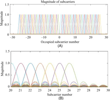
FIGURE 7 Frequency domain representation of the center matrix 𝚲c with r = 2, 𝛽 = 11, Lp = Ls =4, Lcp = 8, M = 52, N = 64. (A)
Subcarriers in the frequency domain. (B) Interpolated figure of (A)
(A) (B) 1.5 1.0 0.5 0 Magnitude –30 –20 –10 0 10 20 30 Magnitude of subcarriers
Occupied subcarrier number
E E EEEEEEEEEE 1.5 1.0 0.5 0 Magnitude 20 21 22 23 24 25 26 27 28 29 30 Subcarrier number
symbol is 64 according to the IEEE 802.11a standard and 52 subcarriers are occupied. The groups on the left and right of the center represent subcarriers with positive and negative frequencies, respectively, which are distributed evenly in the entire band without affecting one another. In particular, it can be observed that the 26th subcarrier, which is the boundary of the band in Figure 7B, maintains orthogonality without being influenced by the generation process of the precoder matrix. In the proposed scheme, the subcarriers in the center part that transmit the data symbols have orthogonality as in CP-OFDM, but the subcarriers of the entire OFDM symbol are nonorthog-onal and restrict the spectrum to suppress the OoBE.
Figure 8 shows the frequency response characteristic of the approximated precoder when the precoder is designed according to the IEEE 802.11a standard. The frequency re-sponse characteristics of CP-OFDM and the proposed scheme
in the passband are identical, but the size of the CP-OFDM gradually decreases while passing the passband, whereas that of the proposed scheme is drastically reduced and the stop-band edge reaches the channel stop-band boundaries. One of the advantages of the proposed scheme is that the stopband edge does not cross the channel band boundary because the signal powers at the frequency boundaries are zero. In the figure, it is confirmed that the precoded signal obtained via the pro-posed scheme does not exceed the channel boundaries of ±10 (MHzGI). The spectral characteristic of the proposed scheme is superior to that of [21], which does not have spectral cliffs at band boundaries.
5
|
BER PERFORMANCE
As OFDM has ideal BER performance except for the issue of OoBE; the performance of the proposed SE-OFDM scheme is compared with that of CP-OFDM. The BER performance is obtained through an AWGN channel and a multipath fad-ing channel, which is modeled as an exponentially delayed channel, h(k) = C ⋅ 10−k∕10, k= 0, 1, ..., 7 [15], where C is the power normalizing factor.
The performance of the proposed SE-OFDM is consistent with that of ideal CP-OFDM; hence, the orthogonality of the IFFT symbol among the precoded OFDM symbols is not dam-aged in the precoding process. Figure 9 shows the performances of OFDM and the proposed scheme when data are transmit-ted through AWGN and exponentially delayed channels. The BER performance of the proposed scheme is evaluated, where the data symbols of quadrature phase shift keying (QPSK), 16-QAM, 32-QAM, and 64-QAM are received through two types of channels. The performance of the proposed SE-OFDM scheme through an AWGN channel is consistent with that of CP-OFDM, which indicates that the IFFT symbol in the pre-coded signal obtained via the proposed scheme is not changed. FIGURE 8 Frequency responses of legacy CP-OFDM and the
proposed scheme with r = 2,𝛽 = 11, Lp = Ls =8, Lcp = 8, LGI = 16,
M = 52, N = 64 OFDM Proposed Magnitude (dB) Frequency (MHz) 20 0 –20 –40 –60 –80 –100 –10 –5 0 5 10 OFDM Proposed
FIGURE 9 BER performances of CP-OFDM and the proposed SE-OFDM scheme with r = 2, 𝛽 = 11, Lp = Ls =8, LGI = 16, M = 52, N = 64
0 5 10 15 20 25 30 Eb/No(dB) 10–5 10–4 10–3 10–2 10–1 100 BE R QPSK, OFDM, AWGN QPSK, SE-OFDM, AWGN QPSK, OFDM, Exponential QPSK, SE-OFDM, Exponential 16-QAM, OFDM, AWGN 16-QAM, SE-OFDM, AWGN 16-QAM, OFDM, Exponential 16-QAM, SE-OFDM, Exponential 32-QAM, OFDM, AWGN 32-QAM, SE-OFDM, AWGN 32-QAM, OFDM, Exponential 32-QAM, SE-OFDM, Exponential 64-QAM, OFDM, AWGN 64-QAM, SE-OFDM, AWGN 64-QAM, OFDM, Exponential 64-QAM, SE-OFDM, Exponential
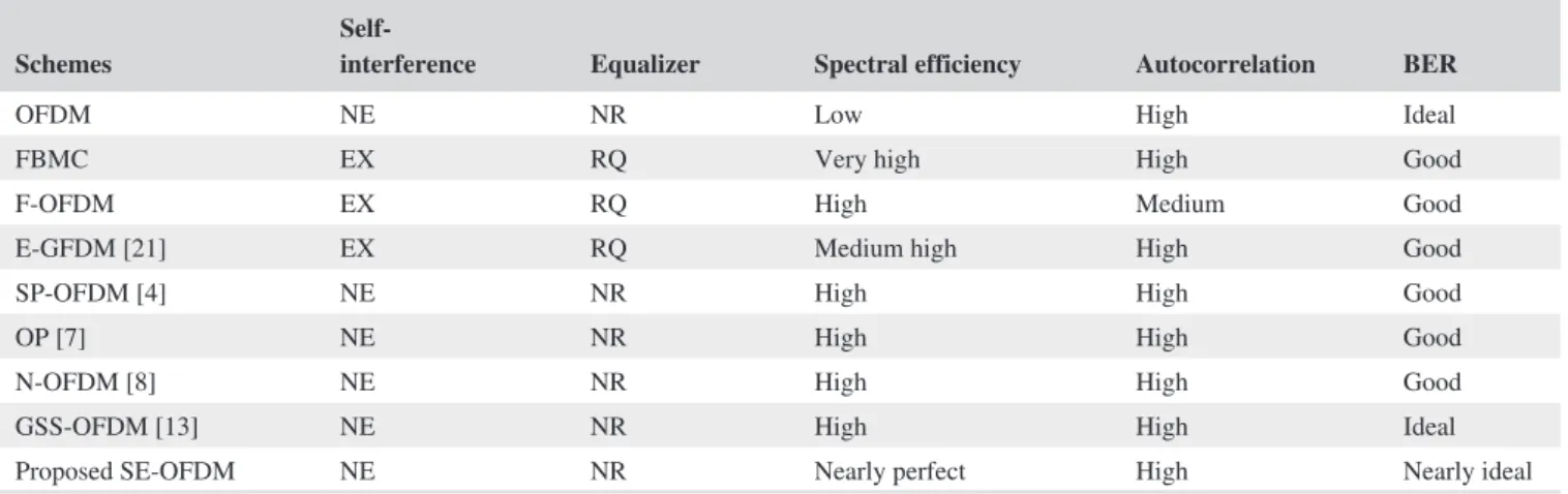
The performance of the proposed SE-OFDM scheme through a multipath fading channel is consistent with that of CP-OFDM, which indicates that the CP-OFDM symbol in the changed signal obtained via the orthogonalizing matrix is negligibly changed. Therefore, it is confirmed that the performances of CP-OFDM and the proposed SE-OFDM scheme are consis-tent for the four modulation schemes and over the two chan-nel environments. The F-OFDM shows that the receiver has the same characteristics as CP-OFDM through equalization. However, the proposed scheme does not require any decoder or equalizer at the receiver owing to the transmission scheme, and thus can be implemented more simply than the F-OFDM. The E-GFDM has also been developed to eliminate self-interfer-ence, improving the BER performance to the same level as that of CP-OFDM. However, this method is inferior to the proposed SE-OFDM method because the spectral characteristics are not recommended for evaluation based on the BER performance alone [21]. Table 1 summarizes the issues discussed so far.
6
|
CONCLUSION
In this study, we proposed the SE-OFDM precoding scheme to block the OoBE of OFDM systems. This method can maintain transmission efficiency by encapsulating existing OFDM without using internal information such as CC or external information such as CSI. The demodulation scheme of SE-OFDM can be performed in the same way as that of legacy OFDM as it does not change the IFFT symbol carrying data in the precoding process. It is also meaningful that the problem of spectrum spreading is solved with-out impairing the advantage of the CP-OFDM. This fact is con-firmed by simulating the OFDM symbol defined in IEEE 802.11a in actual use. To verify the practicality of the proposed scheme, pilot insertion methods were investigated for channel estimation. The mapping matrix used in CP-OFDM is transformed into the precoder matrix via IDFT, permutation, weighting, zero inser-tion, and orthogonalization. It was confirmed from the frequency
response characteristics that the generated precoder could suppress OoBE effectively. The BER performance of the proposed scheme is obtained through two types of channels and compared with that of CP-OFDM, which shows an ideal performance. By confirming that the performance of the proposed scheme is consistent with that of CP-OFDM, the proposed scheme can be considered to have an optimal design. The proposed scheme is expected to be useful for future wireless local area networks and Internet of things, which require small low-power systems.
ACKNOWLEDGMENTS
The authors wish to thank Dr. Lim Jong Soo at ETRI for the helpful discussions and the anonymous reviewers for their valuable comments.
ORCID
Myungsup Kim https://orcid.org/0000-0003-3344-2545
REFERENCES
1. D. Qu et al., Detection of non-contiguous OFDM symbols for
cog-nitive radio systems without out-of-band spectrum synchronization,
IEEE Trans. Wireless Commun. 10 (2011), no. 2, 693–701. 2. A. Sahin, I. Güvenç, and H. Arslan, A survey on multicarrier
com-munications: Prototype filters, lattice structures, and implementation aspects, IEEE Commun. Surveys Tuts. 16 (2014), no. 3, 1312–1338.
3. A. Sahin and H. Arslan, Edge windowing for OFDM based
sys-tems, IEEE Commun. Lett. 15 (2011), no. 11, 1208–1211.
4. C.-D. Chung, Spectral precoding for rectangularly pulsed OFDM, IEEE Trans. Commun. 56 (2008), no. 9, 1498–1510.
5. C.-D. Chung and K.-W. Chen, Spectrally precoded OFDM without
guard insertion, IEEE Trans. Veh. Technol. 66 (2017), no.1, 107–121.
6. W.-C. Chen and C.-D. Chung, Spectrally efficient OFDM pilot
waveform for channel estimation, IEEE Trans. Commun. 65
(2017), no. 1, 387–402.
7. M. Ma et al., Optimal orthogonal precoding for power leakage
suppression in DFT-based systems, IEEE Trans. Commun. 59
(2011), 3, 387–402.
8. J. van de Beek and F. Berggren, N-continuous OFDM, IEEE Commun. Lett. 13 (2009), no. 1, 1–3.
TABLE 1 Scheme-specific characteristics
Schemes Self-interference Equalizer Spectral efficiency Autocorrelation BER
OFDM NE NR Low High Ideal
FBMC EX RQ Very high High Good
F-OFDM EX RQ High Medium Good
E-GFDM [21] EX RQ Medium high High Good
SP-OFDM [4] NE NR High High Good
OP [7] NE NR High High Good
N-OFDM [8] NE NR High High Good
GSS-OFDM [13] NE NR High High Ideal
Proposed SE-OFDM NE NR Nearly perfect High Nearly ideal
Abbreviations: NE, Nonexistence; EX, Existence; NR, Not required; RQ, Required; Nearly Perfect indicates not mathematically perfect, but engineering perfect. Nearly Ideal indicates not mathematically ideal, but engineering ideal.
9. A. Tom, A. Şahin, and H. Arslan, Suppressing alignment: Joint
PAPR and out-of-band power leakage reduction for OFDM-based systems, IEEE Trans. Commun. 64 (2016), 1100–1109.
10. B. Farhang-Boroujeny, OFDM versus filter bank multicarrier, IEEE Signal Process. Mag. 28 (2011), no. 3, 92–112.
11. R. Datta et al., GFDM interference cancellation for flexible
cogni-tive radio PHY design, in Proc. 76th IEEE VTC Fall (Québec City,
Canada), Sept. 2012, pp. 1–5.
12. J. Abdoli, M. Jia, and J. Ma, Filtered OFDM: A new waveform for
future wireless systems, in IEEE Int. Workshop Signal Process.
Adv. Wireless Commun. (Stockholm, Sweden), 2015, pp. 66–70. 13. L. Diez et al., A generalized spectral shaping method for OFDM
signals, IEEE Trans. Commun. 67 (2019), 3540–3551.
14. J. A. C. Bingham, RFI suppression in multicarrier transmission
systems, in Proc. IEEE Global Telecommun. Conf. (London. UK),
Aug. 1996, pp. 1026–1030.
15. T. Weiss et al., Mutual interference in OFDM-based spectrum
pooling systems, in Proc. IEEE Veh. Technol. Conf. (Milano,
Italy), 2004, pp. 1873–1877.
16. D. Qu, A. Wang, and T. Jiang, Extended active interference
cancel-lation for sidelobe suppression in cognitive radio OFDM systems with cyclic prefix, IEEE Trans. Veh. Tech. 59 (2010), 1689–1695.
17. Wireless LAN Medium Access Control (MAC) and Physical
Layer (PHY) Specification: Higher Speed Physical Layer (PHY) Extension in the 5GHz Band, IEEE Std. 802.11a/D5.0, Apr. 1999.
18. Wireless LAN Medium Access Control (MAC) and Physical Layer
(PHY) Specification, IEEE (802.11gTM-2003.).
19. 3rd Generation Partnership Project; Technical Specification
Group Radio Access Network; Evolved Universal Terrestrial Radio Access (E-UTRA); User Equipment (UE) Radio Transmission and Reception (Release 8), 3GPPTS 36.101 V8.15.0 (1811–09).
20. Specification Framework for TGax, IEEE 802.11-15/0132r15. 21. J. K. Jeong et al., Eigendecomposition-based GFDM for
interfer-ence-free data transmission and pilot insertion for channel estima-tion, IEEE Trans. Wireless Commun. 17 (2018), 6931–6943.
AUTHOR BIOGRAPHIES
Myungsup Kim received his BS
de-gree in electronic engineering from Han Yang University, Seoul, Rep. of Korea, in 1986, his MS in electronic engineering from Chungnam National University, Rep. of Korea, in 1991, and PhD in information and communica-tion engineering from Korea Advanced Institute of Science and Technology (KAIST), Seoul, Rep. of Korea, in 1999. From 1986 to 2000, he worked for the Electronics and Telecommunications Research Institute, Daejeon, Rep. of Korea. From 2001 to 2014, he worked for Tunitel Co., Daejeon, Rep. of Korea. Since 2015, he has been with the Department of Mathematical Sciences, KAIST, Daejeon, Rep. of Korea, where he is now a project manager. His main research interests include communication theory and signal processing for future wireless and underwater acoustic communications.
Do Young Kwak received his BS
de-gree in mathematics from Seoul National University, Rep. Korea in 1977, and his PhD in mathematics from the University of Pittsburgh, Pittsburgh, Pennsylvania, USA in 1985. From 1985 to 1990, he was an assistant professor of the Department of Mathematics, Korea Institute of Technology, and from 1990 to 1996, he was an associate professor of the Department of Mathematics, Korea Advanced Institute of Science and Technology (KAIST). Since 1996, he has been a professor of the Department of Mathematical Sciences, KAIST, Daejeon, Rep. of Korea. He has served as the chairman of DMS during 1999–2001. His main research interests in-clude finite element methods, multigrid methods, and other numerical methods to solve partial differential equations.
Ki-Man Kim received his BS, MS,
and PhD degrees in electronic engi-neering from Yonsei University, Seoul, Rep. of Korea, in 1988, 1990, and 1995, respectively. He was a fellow at Yonsei Medical Center, from 1995 to 1996. Since 1996, he has been with the Department of Radio Communication Engineering, Korea Maritime and Ocean University, Busan, Rep. of Korea, where he is now a professor. His main research interests include array signal processing, underwater acoustic/laser communications, and sonar localization.
Wan-Jin Kim received his BS, MS,
and PhD degrees in electronic engi-neering from Pusan National University, Busan, Rep. of Korea, in 2005, 2007, and 2011, respectively. Since 2011, he has been with the Institute of Naval Research, Agency Defense for Development, Changwon, Rep. of Korea, where he is now a senior researcher. His main research interests include sonar/radar signal processing and under-water acoustic communications.
APPENDIX A
Orthogonal matrix P
where (VSVH)−1=(VH)−1S−1V−1= VS−1VH from the
in-verse matrix property and V−1= VH are used, and
Especially, when M = N, the diagonal matrix becomes
and
APPENDIX B
Representation of matrix G as a
product of matrices
Attaching r zeros to each column of matrix R, the matrix is expressed as
where
The matrix B is transformed into the frequency domain as
where L= N + Lp+ Ls. The filter matrix 𝛀is multiplied to
per-form filtering in the frequency domain as
Upon converting this matrix back into the time domain, it becomes
Substituting (14) into (B5), we have
APPENDIX C Center matrix, 𝚲c
We consider the center matrix in G as
As the center matrix of Ep is IN, the center matrix in R can
be written as
Substituting (C2) into (C1), the center matrix can be writ-ten as
Practically, as the prefix and suffix are sufficiently smaller than the IFFT symbol, the approximated matrix of Gc can be
represented by substituting L with N as
The matrices 𝛀 and Wc are represented in SVD forms as
where U𝛀, UW
c, V𝛀, and VWc are unitary, and 𝚺𝛀 and 𝚺Wc are
diagonal.
As the matrices FN and P are all unitary, they cannot
contrib-ute to the eigenvalues of M. The matrix M can be decomposed as (A1)
P= U𝚺VH((U𝚺VH)H(U𝚺VH))
−1 2 = U𝚺VH(V𝚺HUHU𝚺VH)− 1 2 = U𝚺VH(V𝚺H 𝚺VH)− 1 2 = U𝚺VH ( V[ S 0 ] [ S 0 ] VH )−1 2 = U𝚺VH(VS2VH)− 1 2 = U𝚺VH((VSVH)2 )−12 = U [ S 0 ] VHVS−1VH = U [ IM 0 ] VH = UKVH , (A2) K= [ IM 0 ] . (A3) K= IN (A4) P= UVH. (B1) B= ErR, (B2) Er= [ Ip 0(r×N) ] . (B3) K= FLB= FLErR, (B4) 𝚽 = 𝛀FLErR. (B5) G= FHL𝛀FLErR. (B6) G= FHL𝛀FLErWEpP. (C1) Gc= Rc⊗ c h. (C2) Rc=(WEpP) c= WcP. (C3) Gc=(WcP)⊗ c h. (C4) Gc≈ M = FHN𝛀FNWcP. (C5) 𝛀 = U𝛀𝚺𝛀VH𝛀, (C6) Wc= UWc𝚺WcV H Wc,
where UM and VHM are unitary, and f (𝚺Ω,𝚺W
c
)
is the matrix function with two diagonal matrices 𝚺Ω and 𝚺Wc, and can be
expressed as
where 𝚪 ∈ ℝ(M×M)= diag(𝛾1, 𝛾2, ..., 𝛾M) is a diagonal matrix
with M eigenvalues.
Based on the same procedure as that in Appendix A, or-thogonalizing the matrix M yields
From this result, it can be observed that M⊥ is a constant
orthogonal matrix regardless of the matrices Ω and Wc. To
obtain the center matrix, by substituting Ω and Wc with the
identity matrix IN, we have
(C7) M= UMf ( 𝚺𝛀,𝚺Wc ) VHM, (C8) f(𝚺𝛀,𝚺Wc ) = [ 𝚪 0((N−M)×M) ] , (C9) M⊥= U MKV H M. (C10) 𝚲c≈ M⊥|||Wc=𝛀=I N = FHN𝛀FNWcP [( FHN𝛀FNWP)HFHN𝛀FNWP]− 1 2|| || |Wc=𝛀=IN = FHNINFNINP[(FHNINFNINP)HFHNINFNINP]− 1 2 = FHNFNP[(FHNFNP)HFHNFNP] −1 2 = P(PHP)− 1 2 = P.