I. INTRODUCTION
As the Internet services become popular, the number of mobile Internet users has been rapidly increasing with wide popularity of smart phones. It is reported that the number of mobile Internet users will exceed the number of desktop users in near future [1]. The current Internet does not support the IP mobility because an IP address has overloaded semantics as both Identifier (ID) and Locator (LOC). In the network layer, an IP address is used as a LOC to find a destination host and to forward the data packets to the host. This IP address is also used as a host ID to identify host in the transport layer. When a mobile host moves from one subnet to another, it acquires a new IP address. In mobile networks, however, the location of mobile host may continue to change by movement. This
means that the static allocation of LOC (i.e., an IP address) to a host may become problematic in mobile environments. In the meantime, the host ID needs to be kept persistently without change to maintain on-going sessions against movement of a host. Accordingly, ID and LOC need to be separated to support IP mobility [2].
To deal with this problem, the Internet Engineering Task Force (IETF) and the other segments of Internet community have recently been discussing the ID-LOC split concept using the separate namespaces for host ID and locator, which could be helpful for IP mobility support, multi-homing support, routing scalability, and security enhancement.
Recently, Mobile IP (MIP) [3, 4] and Proxy Mobile IPv6 (PMIP) [5] have been developed for IP mobility support. These protocols also use the ID-LOC separation The Mobility Management (MM) is one of the crucial requirements for future mobile networks. The current MM schemes, such as Mobile IP and Proxy Mobile IP, are based on a centralized mobility anchor for mobility control and data delivery. However, it is reported that such a Centralized MM (CMM) approach tends to give a couple of drawbacks, which include non-optimal data route, injection of unwanted data traffics into core networks, and increased cost of network engineering. Recently, some proposals on Distributed MM (DMM) architectures have been discussed so as to overcome limitations of the centralized MM approach, which can be divided into Partially Distributed MM (P-DMM) and Fully Distributed MM (F-(P-DMM). In this paper, we conduct a comparative study on the three MM approaches in terms of total delay and traffic overhead. From numerical results, we see that F-DMM and P-DMM can give better performance than CMM in terms of control/data traffic overhead. However, in terms of total delay, it seems that CMM is preferred to P-DMM and F-DMM in the mesh-like networks, whereas P-DMM and F-DMM is preferred to CMM in the tree-like networks.
Keywords: Mobility management, Centralized, Distributed, Numerical analysis, Comparison
논문번호: TR14-072, 논문접수일자:2014.08.19, 논문수정일자:2015.04.15, 논문게재확정일자:2015.06.02
Moneeb Gohar: Yeungnam University
Seok-Joo Koh(Corresponding Author): Kyungpook National University
A Comparative Analysis of Centralized and Distributed
Mobility Management in IP-Based Mobile Networks
concept for mobility support. That is, Home Address (HoA) is used as ID, whereas Care-of Address (CoA) is employed as LOC to represent the current location of mobile node. However, these protocols are based on a centralized Mobility Management (MM) approach, in which Home Agent (HA) or Local Mobility Anchor (LMA) is used as a centralized mobility anchor by which all control and data packets are processed. Such a centralized anchor allows a mobile host to be reachable, when it is away from its home domain, by ensuring the forwarding of data packets destined to or sent from the mobile host. However, the centralized MM scheme tends to be vulnerable to several problems. First, the centralized mobility anchor tends to induce unwanted control/data traffics into core networks, which may give a big burden to network operators due to large operational costs. In addition, a single point of failure of central node may induce severe degradation of overall system performance and also the increased cost of network engineering.
The IETF has recently discussed the distributed mobility management to overcome limitations of this Centralized MM (CMM) approach [6], [7], which can be divided into the Partially Distributed MM (P-DMM) and the Fully Distributed MM (F-DMM). In P-DMM, only data plane is distributed, as shown in Host Identity protocol (HIP) [8], Locator Identifier Separation Protocol -Alternative Topology (LISP-ALT) [9-11], and Identifier Locator Network Protocol (ILNP) [12]. In F-DMM, both data plane and control plane are distributed, as shown in the examples of DMC [13], DMM-LIS [14], and LISP-DHT [15]. The CMM schemes may incur non-optimal data routes and performance degradations, whereas the DMM schemes can provide optimal data routes and high performance, since the route optimization will be intrinsically supported, and unnecessary traffics can be reduced when the two hosts communicate directly with each other, not relying on a centralized anchor. This will also be helpful to reduce
the handover delay. In this paper, we will conduct a comparative study of the centralized and distributed MM architectures for IP mobility support.
The rest of this paper is organized as follows. In Section II, we review the candidate schemes for centralized and distributed MM architectures. Section III analyzes the performance of the candidate schemes in terms of the total delay and the data/control traffic overhead. Section IV discusses the numerical results and qualitative comparisons for those candidate architectures. Section V concludes this paper.
II. CANDIDATE
ARCHITECTURES FOR
MOBILITY MANAGEMENT
1. Overview of Mobility Management
Architectures
The candidate mobility schemes, considered in this paper, are all based on the ID-LOC separation concept, and thus they need an ID-LOC mapping agent. However, in the viewpoint of how to provide mobility support, those schemes can be classified into CMM and DMM, and DMM is further divided into Partial DMM (P-DMM) and Full DMM (F-DMM). Before going into the detailed description, let us compare the candidate MM schemes in the architectural perspective, as described in Table 1.
In the mobility perspective, MIP [3], [4] and PMIP [5] can be viewed as a centralized MM architecture, in which all control and data traffics are processed by a centralized agent, such as HA and LMA. Data packets are first delivered to the centralized node, and then the centralized node will forward the data packets to the corresponding host. In the ID-LOC mapping control, the centralized mapping agents, HA and LMA, are used for ID-LOC Table 1. Comparison of mobility management architectures
Architectures Relevant Protocols
ID-LOC Mapping Agent Plane Separation(Data-Control)
Data Delivery Model Mapping Control Model
CMM MIP [3],[4], PMIP [5] HA (MIP), LMA(PMIP) Integrated Data-First(Centralized) Centralized P-DMM HIP [8] LISP-ALT [9]~[11], ILNP [12] RVS (HIP), MS (LISP-ALT), D-DNS (ILNP) Separated Query-First(Distributed) Centralized F-DMM LISP-DMC [13], DMM-LIS [14], LISP-DHT [15] TR/MS (LISP-DMC, DMM-LIS, LISP-DHT) Separated Query-First(Distributed) Distributed
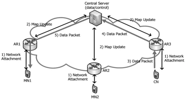
performed based on a central server. Figure 1 depicts the basic operations for map update (or registration) and data delivery in CMM, in which it is assumed that the control operations for map update is performed by a network router, rather than by a host.
In the figure there are the three hosts, denoted by two Mobile Nodes (MNs) and a Correspondent Node (CN). When each host is attached to its nearest Access Router (AR) in Step 1, its ID and LOC will be registered or updated to the central server by using a Map Update message (Step 2). Now, we assume that CN wants to send a data packet to MN1. The data packet of CN will first be delivered to AR3 (Step 3). AR3 forwards the data packet to the central server, since it has no information of LOC of MN1 (Step 4). On reception of this data packet, the central server will look up its ID-LOC mapping table which has been updated in the map update operation, so as to find the LOC of MN1. Now, the data packet is delivered to AR1 of MN1, further to MN1 (Step 5).
Typical examples of CMM include the currently well-known mobility protocols, such as MIP and PMIP. In MIP and PMIP, the central server of CMM corresponds to the Home Agent (HA) of MIP or the Local Mobility Anchor (LMA) of PMIP. In MIP, the Binding Update message corresponds to Map Update message. In PMIP, LMA is used as the control server (or mapping system), and Mobile Access Gateway (MAG) corresponds to an AR in CMM. In terms of control messages, the PBU message of PMIP can be regarded as Map Update message mapping management.
HIP [8], LISP-ALT [9]~[11] and ILNP [12] can be regarded as a partially distributed MM approach, in which the data plane is separated from the control plane. For distributed ID-LOC mapping management, some dedicated mapping agents are used: Rendezvous Server (RVS) in HIP, Map Server (MS) in LISP, and Dynamic Domain Name System (D-DNS) in ILNP. All mobility control traffics are processed by these mapping control entities. The mapping query operations will be performed with the mapping agents to find the location of mobile hosts, before transmission of data packets. It is noted that LISP will be MM protocol.
In the meantime, LISP-DMC [13], DMM-LIS [14], and LISP-DHT [15] can be classified as the fully distributed MM approach, in which both control plane and data plane are separated. That is, a centralized mapping agent is not used. Instead, the mapping query operations will be performed to obtain the location of mobile hosts by applying a hash function or by multicasting of a map query message. Each of the candidate MM schemes for F-DMM has its distinctive features, but the overall MM mechanisms are based on the fully distributed approach for all of the associated schemes. The details of each candidate scheme will be discussed in the subsequent sections.
2. Centralized Mobility Management (CMM)
In CMM, both data delivery and control function areCN (Step 5). Now, the data packet can be delivered from CN to MN1 (Step 6).
The recently proposed protocols for ID-LOC separation, such as HIP [8], LISP-ALT [9-11], and ILNP [12], can be classified as P-DMM. In HIP, the Rendezvous Server (RVS) is used as the control server, and HIP I1 and R1 messages correspond to the Map Query and Map Query ACK messages, respectively. In LISP-ALT, the Map Server (MS) is used as the control server, and LISP Tunnel Router corresponds to AR of P-DMM. The Map Register, Map Request, and Map Reply messages of LISP can be regarded as the Map Update, Map Query, and Map Query ACK messages of P-DMM. On the other hand, in case of ILNP, the Dynamic Domain Name System (D-DNS) is used as the control server which requires an extension of the legacy DNS.
Now, we describe the HIP, LISP-ALT and ILNP schemes on the basis of Figure 2. In HIP, a locator and a host identifier are separated, in which a 128-bit Host Identity Tag (HIT) is used as a host ID, and an IP address of the host is used as a LOC. That is, HIT is the node identifier, and IP address is used for packet routing in the network. It is noted that HIP depends on a centralized RVS for LOC binding update in the global scale, which may create a lot of unnecessary signaling and control messages in mobile networks. This makes the HIP approach very inconvenient. To deal with this problem, the work in [16] proposed an enhanced scheme for HIP. The main idea is similar to HIP. However, it deploys a of CMM. Based on Figure 1, we are going to describe the
operations of MIP and PMIP. In MIP, when MN1 is attached to AR1, it performs the map update operation with HA. Then, CN tries to communicate with MN1. Now, CN transmits a data packet to MN1 via HA. In PMIP, when MN1 is attached to AR1 (MAG), AR1 will perform the map update operation with LMA. Now, CN can send data packets to MN1 via LMA.
3. Partially Distributed MM (P-DMM)
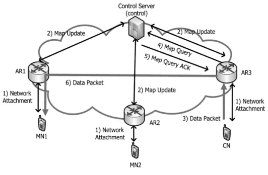
In P-DMM, both data delivery and control function are separated, and an optimal data path is obtained from the control server by using the 'map query'function, before data transmission. That is, the data delivery function is distributed by using an optimal route, whereas the control function can still be regarded as a centralized scheme. The name of P-DMM comes from this observation. Figure 2 illustrates the basic operations for map update, map query, and data delivery in P-DMM.
In the figure, when each host is attached to its nearest AR (Step 1), its ID and LOC are registered with the control server by using a Map Update message (Step 2). When CN sends a data packet to MN1 (Step 3), AR3 of CN sends a Map Query message to the control server (step 4). On reception of this message, the central server will look up its ID-LOC mapping table so as to find the LOC of MN1. Finally, the server responds with a Map Query ACK message (containing the LOC of MN1) to AR3 of
which may incur significant overhead of control messages at MS. To deal with this problem, the work in [18] proposed an enhanced scheme of LISP-MN. The main idea is the same with LISP-MN, but it deploys a Local Map Server (LMS) at the gateway of mobile network so as to provide a localized mobility control. In Figure 2, when MN1 is attached to AR1, then it will perform the map update operation with LMS (control server). LMS will also perform the map update operation with the global MS. For data delivery, CN will first send a Map Query message to LMS. The LMS will respond with Map Query ACK message to CN. Now, CN can send the data packet to MN1.
ILNP [12] is another scheme for ID-LOC separation, which is based on the address re-writing, in which a 128-bit IPv6 address will be divided into the upper 64 128-bits for LOC and the lower 64 bits for ID. For mobility support, a Dynamic DNS (D-DNS) server is used for mapping between ID and LOC of hosts. In Figure 2, when MN1 is connected to AR1, then it will perform the map update operation with D-DNS (control server). In the data delivery operation, CN will first send a Map Query message to D-DNS. D-DNS then responds with a Map Query ACK message to CN. Now, CN can send data packets to MN1 through an optimized route.
Local RVS (LRVS) at the gateway of mobile network to provide a localized mobility control. In Figure2, when MN1 is connected to an access router 1 (AR1), it configures its LOC. Then, MN1 performs the map update operation with a Localized RVS (LRVS).The LRVS also performs the binding update operation with the global RVS. In data delivery, as indicated in Figure 2, CN sends a data packet to MN1. To do this, CN will initiate the HIP 4-way handshaking operations with MN1 for connection setup. The first I1 packet is sent to LRVS, and LRVS will forward the I1 packet to MN1. After receiving the I1 packet, MN1 responds with a R1 message to CN. The other two messages, I2 and R2, are exchanged between CN and MN for completion of security association. Now, CN can send the data packets directly to MN1.
On the other hand, LISP has recently been made in the IETF, which splits the current IP address space into Endpoint IDentifier (EID) and Routing LOCator (RLOC). To support the LISP mobility, the LISP is extended to the LISP-MN architecture in [17], in which it is assumed that each mobile node implements the light-weight tunnel router functionality in mobile networks. In this architecture, a Map Server (MS) is used as an anchor point for MNs. That is, a MN will maintain the map cache and directly communicate with MS. It is noted that LISP-MN depends on a central MS for mapping control operations,
4. Fully Distributed MM (F-DMM)
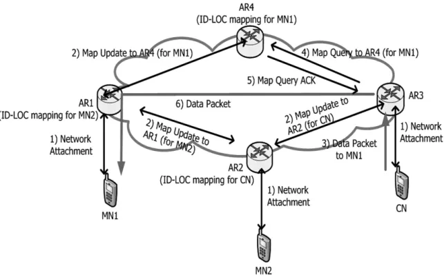
In F-DMM, the control server is not used, differently from P-DMM. Instead, both data delivery and control function are performed by ARs in the distributed way. Figure 3 illustrates the operations for map update, map query, and data delivery in F-DMM.
As shown in the figure, each AR performs the mapping control function, instead of the control server. The ID-LOC mapping management is performed based on a Distributed Hash Table (DHT) or hash function. That is, the AR that is responsible for ID-LOC mapping management for a certain host will be determined by applying a DHT or hash function to the ID of the concerned host. In this way, the overhead of mapping management will be distributed onto a lot of ARs in the network, not relying on a single control server. From the example of Figure 3, we can see that the ID-LOC mapping information of MN1 is managed by AR4, MN2 is allocated to AR1, and CN is assigned to AR2.
When a host is attached to AR (Step 1), the attached AR will determine which AR in the network shall be responsible for ID-LOC mapping management for the concerned host. Then, the attached AR sends a Map Update message to the determined AR (Step 2). When CN sends a data packet to MN1 (Step 3), AR3 of CN will look up its DHT table or perform its hash function so as to find
which AR in the network has the ID-LOC mapping information of MN1. After that, AR3 of CN sends a Map Query message to AR4 that has the associated mapping information (Step 4). In turn, AR4 will respond with a Map Query ACK message to AR3 (Step 5). Now, the data packet can be delivered from CN to MN1 over an optimized path (Step 6).
Several works on distributed ID-LOC management have so far been made. Most of them are based on the DHT, and each scheme uses a distinctive DHT or hash function. Typical examples of the F-DMM architecture include LISP-DMC [13], DMM-LIS [14], and LISP-DHT [15].
In LISP-DMC, AR/TR performs the processing of both data and control messages, but the binding update operation is not performed. That is, the central server, such as MS, is not used. Instead, the binding query operations are performed to get the LOC of the concerned host by multicast. The Map Request message of LISP-DMC corresponds to the Map Query message of F-DMM. In DMM-LIS, a network is divided into a lot of domains. Each domain contains a Mapping Server (MS) and several TRs. The MS will maintain the mapping information between global EID and Autonomous System Number (ASN) of each domain. Each MS also maintains the mapping between ASN and TR. Each TR constitutes one-hop DHT ring. The Map Register and Map Request messages of DMM-LIS correspond to the Map Update and
(a) Mesh Topology
Figure 4. Network topologies for analysis
connected each other. We also define the parameters used for analysis in Table 2.
In the table, we denote Tx-y(S) by the transmission delay of a message with size S sent from x to y via
'
wired'
link. Then, Tx-y(S) is expressed as Tx-y(S)= [(S/Bw)+Lw+Tq]. The transmission delay over the wireless link is neglected, since it is a common for all of the candidate schemes.
In the analysis, the Total Delay (TD) consists of the Binding Update Delay (BUD), the Binding Query Delay (BQD) and Data Delivery Delay (DDD). That is, TD=BUD+BQD+DDD.
2. Analysis of Total Delays (TD)
2.1. CMM
In CMM, when MN is attached to a new AR, the AR will perform the binding update operation with the control server (MA). The MA updates its database. If all ARs are inter-connected in the mesh topology, the distance between two ARs or the distance between AR and MA is only one-hop link. In the tree topology, the distance between AR and MA is more than one-hop link. Accordingly, the Binding Update Delay (BUD) of CMM for each topology can be represented as follows.
CMM_BUDMesh=2×TAR-MA(Sc) CMM_BUDTree=2×
β
×TAR-MA(Sc)The binding query delay of CMM is 0, because the binding query operation is not performed. Thus, the Binding Query Delay (BQD) of CMM can be represented Map Query messages of F-DMM. On the other hand,
LISP-DHT is a mapping distribution system based on DHT, which is designed to take full advantage of the DHT architecture so as to build an efficient and secure ID-LOC mapping system.
Based on Figure 3, we describe the operations of LISP-DMC schemes. In LISP-DMC, when MN1 is attached to AR1, then AR1 will store its ID-LOC in its binding cache. AR1 will not perform the map update operation. Now, CN sends a data packet to AR3. Then, AR3 will send a Map Query message to all ARs by multicast. Only the corresponding AR, where MN is staying, will respond with a Map Query ACK message to AR3. Now, AR3 will forward the data packets to MN1 through an optimized route.
III. PERFORMANCE ANALYSIS
In this section, we analyze the traffic overhead at the central node and the total delay for binding update, binding query and data delivery.1. Network Models for Analysis
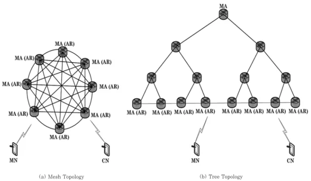
For analysis, we consider the two network topologies: mesh and tree, as illustrated in Figure 4. In the mesh topology, all Access Routers (ARs) are directly connected to each other. Only a single AR will perform the functionality of Mobility Agent (MA) for CMM and P-DMM. In F-DMM, each AR will perform the functionality of MA.
For CMM and P-DMM, the centralized MA is located at the root node in the tree topology. On the other hand, in F-DMM, MAs are located at leaf nodes in a balanced binary tree. We assume that the leaf nodes in the tree are Table 2. Parameter used for a numerical nalysis
Parameter Sc Sd Bw Lw
β
σ
Tq NHost NAR DescriptionSize of control packets (bytes) Size of data packets (bytes) Wired link bandwidth (Mbps)
Wired link delay (ms)
Hop count between node AR and MA in the tree topology Hop count between node AR and AR in the tree topology
Average queuing delay at each node (ms) Number of host per AR Number of ARs per domain
PDMM_BQDMesh=2×TAR-MA(Sc)
PDMM_BQDTree=2×
β
×TAR-MA(Sc)In data delivery, the data traffic will be delivered through an optimized route. So, the data delivery delay of P-DMM can be represented as follows.
PDMM_DDDMesh=2×TAR-AR(Sd)
PDMM_DDDTree=2×
σ
×TAR-AR(Sd)So, we obtain the total delay of P-DMM as follows:
PDMM_TDMesh=PDMM_BUDMesh+PDMM_BQDMesh
+PDMM_DDDMesh
PDMM_TDTree=PDMM_BUDTree+PDMM_BQDTree +PDMM_DDDTree
2.3. F-DMM
In F-DMM, when MN is attached to a new AR, the AR will perform the binding update operation with the distributed MA. Each MA has a rich finger table on all MAs. The Map Update and Map Query messages are transmitted through an optimal path. The probability for F-DMM is ((NAR-2)/NAR). Accordingly, the Binding Update Delay (BUD) of F-DMM can be represented as follows.
FDMM_BUDMesh=((NAR-2)/NAR)×(2×TAR-AR(Sc)) FDMM_BUDTree=((NAR-2)/NAR)
×(2×
σ
×TAR-AR(Sc))In F-DMM, the binding query delay from CN to MN can be calculated as follows. First, AR performs the map query operation with a distributed AR/MA so as to find the LOC of MN. Then, MA will look up for the LOC of as follows.
CMMBQD
Mesh=CMMBQDTree=0
In data delivery, a data packet is first delivered to MA, and MA will forward the data packet to the concerned host. So, the data delivery delay of CMM is as follows.
CMM_DDDMesh=2×TAR-MA(S d) CMM_DDDTree=2×
β
×TAR-MA(Sd)
So, we get the total delay of CMM as follows:
CMM_TDMesh=CMM_BUDMesh+CMM_BQDMesh +CMM_DDDMesh
CMM_TDTree=CMM_BUDTree+CMM_BQDTree +CMM_DDDTree
2.2. P-DMM
In P-DMM, when MN is attached to a new AR, the AR will perform the binding update operation with MA. The MA updates its database. Accordingly, the Binding Update Delay (BUD) of P-DMM is represented as follows.
PDMM_BUDMesh=2×TAR-MA(Sc) PDMM_BUDTree=2×
β
×TAR-MA(Sc)The binding query delay of P-DMM from CN to MN can be calculated as follows. First, AR performs the map query operation with MA to find the LOC of MN. Then, MA will look for the LOC of MN in its database. After lookup, the MA responds to AR with a Map Query ACK message. Thus, the binding query delay of P-DMM can be represented as follows.
CMM_TOMesh=CMM_TOTree=Sc×NHost×NAR+Sd ×NHost×NAR
3.2. P-DMM
In P-DMM, we calculate the traffic overhead by the number of mapping control to be processed by MA. For mapping update, all hosts in the network will send the Map Update messages to MA. Thus, the Map Update message of Sc×NHost×NARshall be processed by MA. For data transmission, each host sends Map Query messages to MA. Thus, the Map Query messages of Sc× N
Host×NARshall be processed by MA. Accordingly, we
get the traffic overhead of P-DMM for each topology is as follows.
PDMM_TOMesh=PDMM_TOTree =2×(Sc×NHost×NAR)
3.3. F-DMM
In F-DMM, we calculate the traffic overhead by the number of mapping control to be processed by AR/MA. It is assumed that mobile hosts are equally distributed in the network. For mapping update, all hosts in the network will send the Map Update messages to its own AR. Each AR/MA will process the binding update messages of Sc× (N
Host/NAR). After that, the AR/MA will perform a hash
function to determine the designated AR/MA for the concerned host. If the hashed value of the host is the other AR/MA, then the AR will forward a Map Update message to the designated AR/MA of host. Thus, the Map Update message of Sc×(NHost-NHost/NAR) shall be processed. For data delivery, each host sends a Map Query messages to AR/MA. Each AR/MA will process the map query messages of S
c×(NHost/NAR). After that, AR/MA will
perform the hash function to determine the designated AR/MA of host. Then, AR will forward the Map Query message to the designated AR/MA of host. Thus, the Map Query messages of S
c×(NHost-NHost/NAR) shall be
processed by MA/AR. The data packets of Sd× (N
Host/NAR) shall also be processed by AR/MA. Let us
assume that the probability for F-DMM is (NAR-2)/NAR. Accordingly, we get the traffic overhead of F-DMM for each topology is as follows.
MN in its database. After lookup, the designated AR/MA responds to AR/MA with a Map Query ACK message. We assume that mobile hosts are equally distributed in the network with the probability of (NAR-2)/NAR. Thus, the binding query delay of F-DMM can be represented as follows.
FDMM_BQDMesh=((NAR-2)/NAR)×(2×TAR-AR(Sc))
FDMM_BQDTree=((NAR-2)/N
AR)×(2×
σ
×TAR-AR(Sc))In data delivery, the data traffic will be through an optimized route. So, the data delivery delay of F-DMM can be represented as follows.
FDMM_DDDMesh=2×TAR-AR(Sd)
FDMM_DDDTree=2×
σ
×TAR-AR(Sd)So, we obtain the total delay of F-DMM as follows:
FDMM_TDMesh=FDMM_BUDMesh+FDMM_BQDMesh
+FDMM_DDDMesh
FDMM_TDTree=FDMM_BUDTree+FDMM_BQDTree +FDMM_DDDTree
3. Analysis of Traffic Overhead (TO)
3.1. CMM
In CMM, we calculate the traffic overhead by the number of mapping control and data traffic to be processed at MA. It is assumed that mobile hosts are equally distributed in the network. For mapping update, all hosts in the network will send the Map Update messages to MA. Thus, the Map Update message of S
c×
NHost×NAR shall be processed by MA. For data transmission, the data packets S
d×NHost×NARshall also
be processed at MA. Accordingly, we get the traffic overhead of CMM for each topology is as follows.
FDMM_TOMesh=FDMM_TOTree
=((NAR-2)/NAR)×{2×(Sc×(NHost -NHost/NAR))+2×Sc×(NHost/NAR) +Sd×(NHost/NAR)}
IV. RESULTS AND DISCUSSION
Based on the analysis given so far, we now compare the performances of the proposed schemes. For numerical analysis, the default values of parameters are configured as given in Table 3 by referring to [18], [19]. Among these parameters, we note that
β
, Tq, Lw, NHost, and NAR may depend on the network conditions of mobile networks. Thus, we will compare the performance of candidate schemes by varying those parameter values.1. Total Delays (TD)
1.1. Mesh Topology
Figure 5 and Figure 6 compare the total delays for different average queuing delay at each node (T
q) and
wired link delay (Lw). It is shown in the figures that the total delay linearly increases, as T
qand Lwget larger, for
the three candidate schemes. We can see that P-DMM and F-DMM give slightly worse performance than CMM. This is because P-DMM and F-DMM perform the binding update and query operations. In the meantime, it is shown that CMM gives the best performance among the candidate schemes, since the binding query operation is not performed in CMM.
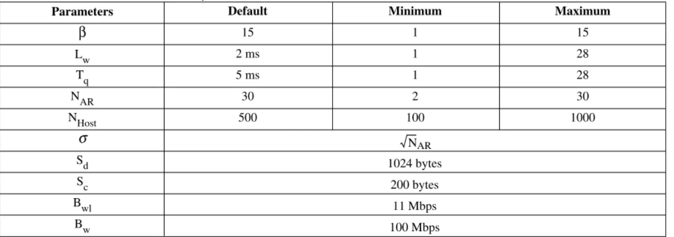
1.2. Tree Topology
Figure 7 compares the total delay for different hop count between AR and MA (
β
). In the figure, we can seeFigure 5. Impact of Tqon total delay in mesh topology
Default 15 2 ms 5 ms 30 500 Minimum 1 1 1 2 100 Maximum 15 28 28 30 1000 Parameters
β
Lw Tq NAR NHostσ
Sd Sc Bwl BwTable 3. Parameter values used for analysis
√
NAR1024 bytes 200 bytes
11 Mbps 100 Mbps
that P-DMM and CMM give better performance than F-DMM, until the hop count reaches 5. However, if the hop count is greater than 5, the proposed F-DMM scheme provides smaller delays than CMM and P-DMM, and the performance gaps between the candidate schemes get larger, as
β
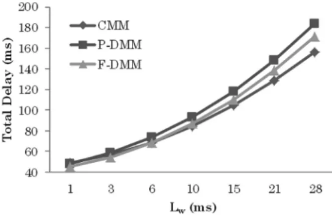
increases. This is because the F-DMM does not use the centralized MA for binding update and query operation, and the data delivery and query operations are performed in the distributed way. In the figure it is shown that P-DMM gives better performance than CMM. This is because P-DMM uses an optimal path for data delivery.Figure 8 and Figure 9 illustrate the impact of average queuing delay at each node (T
q) and wired link delay (Lw)
on total delays. We can see that the total delay linearly increases, as T
qand Lwget larger, for the three candidate
schemes. We can see that CMM gives worse performance than P-DMM and F-DMM. This is because CMM
performs the binding update operations with a centralized MA, while there is no query operation, and the data packets are directly delivered to the centralized MA. On the other hand, it is shown in the figure that F-DMM gives the best performance among the candidate schemes. This is because the F-DMM does not use the centralized MA, and the data delivery and query operations are performed in the distributed way.
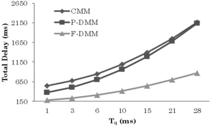
Figure 10 shows the impact of the number of ARs in the domain on total delay. From the figure, the total delay slightly increases, as N
ARgets larger for the P-DMM and
F-DMM schemes. This implies that the distributed schemes are much preferred in mobile network with a maximum number of ARs in the domain. Overall, F-DMM and P-F-DMM provide much smaller total delays than CMM. This is because the data delivery operation is performed through an optimal path. On the other hand,
F-Figure 6. Impact of Lwon total delay in mesh topology
DMM gives the best performance among the candidate schemes.
2. Traffic Overhead (TO)
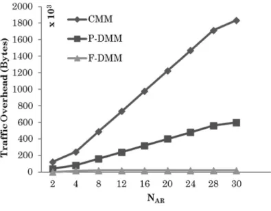
Figure 11 and Figure 12 compare the number of control/data messages to be processed by MA or AR/MA for different NHostand NAR. In Figure 11, we can see that the F-DMM and P-DMM schemes provide smaller traffic overhead than CMM. This is because all of the mapping control and data messages shall be processed by MA in CMM. On the other hand P-DMM gives worse performance than F-DMM. This is because that all of the mapping control messages are processed by MA. It is
shown in the figure that F-DMM gives the best performance among the candidate schemes. This is because all the control traffics are distributed onto the AR/MAs in the network. The gaps of performance between centralized and distributed schemes get larger, as the number of hosts in the network increases. In Figure 12, we can see that the traffic overhead of F-DMM is not affected by the number of ARs in the domain. This is because all of the mapping control traffics are processed by the AR/MAs in the network.
3. Discussion
In addition to the numerical analysis and results until
Figure 8. Impact of Tqon total delay in tree topology
now, we discuss the qualitative comparison of CMM and DMM. Table 4 summarizes the pros and cons of CMM and DMM by functionality.
CMM schemes maintain the data path between a central network entity and the host. A single data path is maintained per host. The tunnel management is easy to deploy and broadly used. However, those tunnels tend to induce data overhead due to encapsulations and data processing. Tunnels header compression may also add further processing. This induced overhead may impact on core network links as well as access networks. In the centralized schemes, the central entities need to maintain per-user tunneling contexts, which may cause scalability issues. The aggregated traffic is huge, and the mobile data
traffic explosion may occur. The data path centralization tends to induce the single point of failure and bottleneck issues.
On the other hand, in DMM schemes, only the necessary and temporary tunnels are used between access nodes. If a mobile node does not move, its data traffic can be simply routed without additional overhead. The tunnel endpoints are located at the access level, thus the rest of the network is not affected. This can reduce the processing overhead for encapsulation and de-capsulation. However, each access node may need to be maintained in per-user context. An active host may have parallel data flows that are anchored at different access nodes. The user contexts and tunnel maintenance are distributed
Figure 10. Impact of NARon total delay in tree topology
among access nodes, which is helpful to avoid the single point of failure and bottleneck issues. When the flows of a moving host are anchored on different access nodes, they require several parallel updates. Delays and packet loss may be affected by the distance between access nodes.
V. CONCLUSIONS
In this paper, we have conducted a comparative study for the candidate MM architectures: Centralized MM (CMM), Partially Distributed MM (P-DMM), and Fully
Distributed MM (F-DMM) for IP mobility support in future mobile networks.
By performance analysis, the three candidate schemes are compared in terms of total delay and traffic overhead. From numerical results, we see that F-DMM and P-DMM can gives better performance than CMM in the mesh-like and tree-like networks in terms of traffic overhead. However, from the perspective of total delay, CMM may be preferred to P-DMM and F-DMM in the mesh topology, whereas P-DMM and F-DMM are preferred to CMM in the tree topology.
Figure 12. Impact of NARon traffic overhead
Table 4. Qualitative analysis of CMM and DMM schemes
DMM
No tunnel is required when the active is motionless
Avoid unnecessary overhead
Temporary tunnel endpoints distributed at access node level
Avoid single point of failures Multiple inter-access node tunnels per host situation
Avoid scalability issues
Contexts replication (e.g. for a host with flows on different anchors)
CMM Single path per host
Permanent tunnel per active host Overhead in processing
Easy to deploy
Huge aggregated traffic in network Bottlenecks/single point of failure Easy to administrate
Dimensioning of central mobility agents, scalability Pros Cons Pros Cons Pros Cons Functionality Encapsulation Tunnel management User context
Acknowledgment
This research was partly supported by the Basic Science Research Program of NRF(2010-0020926).
[References]
[1]
Morgan Stanley Report, Internet trends,
http://www.morganstanley.com/, 2013.
[2]
J. Saltzer, On the naming and binding of network
destinations, IETF RFC 1498, Aug. 1993.
[3]
C. Perkins, et al., IP Mobility Support for IPv4, IETF
RFC 3344, Aug. 2002.
[4]
D. Johnson, et al., Mobility Support in IPv6, IETF RFC
3775, Jun. 2004.
[5]
S. Gundavelli, et al., Proxy Mobile IPv6, IETF RFC
5213, Aug. 2008.
[6]
H. Chan, et al., Requirements for Distributed Mobility
Management, IETF RFC 7333, Aug. 2014.
[7]
D. Liu, et al., Distributed Mobility Management:
Current Practices and Gap Analysis, IETF RFC 7429,
Jan. 2015.
[8]
P. Jokela, et al., Host Identity Protocol, IETF RFC 5201,
Apr. 2008.
[9]
D. Farinacci, et al., Locator/ID Separation Protocol,
IETF RFC 6830, Jan. 2013.
[10] V. Fuller, et al., Locator/ID Separation Protocol -
Alternative Topology (LISP+ALT), IETF RFC 6836,
Jan. 2013.
[11] V. Fuller, et al., LISP Map Server Interface, IETF RFC
6833, Jan. 2013.
[12] RJ Atkinson, et al., Identifier-Locator Network Protocol
(ILNP) Architecture Description, IETF RFC 6740,
Nov. 2012.
[13] M. Gohar, et al., ''Network-based Distributed Mobility
Control in Localized Mobile LISP Networks,''
IEEE Communications Letters, Vol. 16, Jan. 2012,
pp. 104-107.
[14] F. Qiu, et al., ''A Distributed Mobility Management
Scheme in Networks with the Locator/Identifier
Separation,'' International Journal of Communications
Systems,'' Vol. 27, Oct. 2014, pp. 1874-1893.
[15] L. Mathy, et al., ''LISP-DHT: Towards a DHT to
Map Identiers onto Locators,'' Conference of ReArch'
08, Dec. 2008.
[16] S. Nova
'czki, et al., ''Micromobility Support in HIP,''
Conference of IEEE MELECON, May 2006.
[17] D. Farinacci, et al., LISP Mobile Node, IETF Internet
Draft, draft-meyer-lisp-mn-12, Jan. 2015.
[18] M. Gohar, et al., ''Distributed Mapping Management
of Identifiers and Locators in LISP-based Mobile
Networks,'' Wireless Personal Communications,
Vol. 72. No. 1, Sep. 2013, pp. 565-579.
[19] D. Xie, et al., "URCP: Universal Rate Control Protocol
for Real-Time Communication Applications,"
Microsoft Research Technical Report,
MSR-TR-2013-64, Jun. 2013.
Moneeb Gohar
He received B.S. degree in Computer Science from University of Peshawar, Pakistan, and M.S. degree in Technology Management from Institute of Management Sciences, Pakistan, in 2006 and 2009, respectively. He also received Ph. D degree from the School of Computer Science and Engineering in the Kyungpook National University, Korea, in 2012. From September 2012 to September 2014, he worked as a Post-Doctoral researcher for Software Technology Research Center (STRC) in Kyungpook National University, Korea. He has been as an International Research Professor with the Department of Information and Communication Engineering in the Yeungnam University since September 2014. His current research interests include Network Layer Protocols, Wireless Communication, Mobile Multicasting, Wireless Sensors Networks, TRILL, and Internet Mobility. E-mail: [email protected]
Seok-Joo Koh
He received the B.S. and M.S. degrees in Management Science from KAIST in 1992 and 1994, respectively. He also received Ph.D. degree in Industrial Engineering from KAIST in 1998. From August 1998 to February 2004, he worked for Protocol Engineering Center in ETRI. He has been as a professor with the school of Computer Science and Engineering in the Kyungpook National University since March 2004. His current research interests include mobility management in the future Internet, IP mobility, multicasting, LED-based visible lights communication, IoT and SCTP. He has so far participated in the international standardization as an editor in ITU-T SG13 and ISO/IEC JTC1/SC6.