Introduction
Autonomous driving technology is currently being used effectively for the planting, spraying, and harvesting of row crops in Europe and America. However, headland turning at the end of a row is a challenging task to complete in fully autonomous driving. Typical Korean headland turning allows for fewer turning options owing to the narrow turning space available. Conventional vehicles with front wheel steering have a limited turning
radius owing to their mechanical link geometry, which requires a relatively large headland.
In South Korea, the average farm size is much smaller than those in Europe or America. The Korean agricultural area in 2015 was reported as 1.679 million ha cultivated by 1.089 million farm households, which results in an average of 1.54 ha landholding per farm. Of the total agricultural area, garlic cultivating area was 19,317 ha involving 122,730 farms, which results in 0.16 ha per farm (KOSIS, 2015). This small area used as garlic farming land has been the primary obstacle in mechanizing and automating Korean garlic agriculture.
This research focuses on providing a sustained and
Development of Optimized Headland Turning Mechanism on an
Agricultural Robot for Korean Garlic F arms
JongWoo Ha1,2, ChangJoo Lee1, Abhishesh Pal1, GunWoo Park1, HakJin Kim2*
1HADA co.,ltd. , Ik-San, 54569, Korea
2Dept. of Biosystems and Biomaterials Engineering, College of Agriculture and Life Sciences, Seoul National University,
Seoul, 08826, Korea
Received: September 2th, 2018; Revised: October 26th, 2018; Accepted: November 9th, 2018
Purpose: Conventional headland turning typically requires repeated forward and backward movements to move the farming equipment to the next row. This research focuses on developing an upland agricultural robot with an optimized headland turning mechanism that enables a 180° turning positioning to the next row in one steering motion designed for a two-wheel steering, four-wheel drive agricultural robot named the HADA-bot. The proposed steering mechanism allows for faster turnings at each headland compared to those of the conventional steering system. Methods: The HADA-bot was designed with 1.7-m wide wheel tracks to travel along the furrows of a garlic bed, and a look-ahead path following algorithm was applied using a real-time kinematic global positioning system signal. Pivot turning tests focused primarily on accuracy regarding the turning radius for the next path matching, saving headland turning time, area, and effort. Results: Several test cases were performed by evaluating right and left turns on two different surfaces: concrete and soil, at three speeds: 1, 2, and 3 km/h. From the left and right side pivot turning results, the percentage of lateral deviation is within the acceptable range of 10% even on the soil surface. This U-turn scheme reduces 67% and 54% of the headland turning time, and 36% and 32% of the required headland area compared to a 50 hp tractor (ISEKI, TA5240, Ehime, Japan) and a riding-type cultivator (CFM-1200, Asia Technology, Deagu, Rep. Korea), respectively. Conclusion: The pivot turning trajectory on both soil and concrete surfaces achieved similar results within the typical operating speed range. Overall, these results prove that the pivot turning mechanism is suitable for improving conventional headland turning by reducing both turning radius and turning time.
Keywords: Agricultural robot, Minimum-time headland turning, Minimum turning radius, Precision agriculture, Upland robot
J. Biosyst. Eng. 43(4):273-284. (2018. 12) https://doi.org/10.5307/JBE.2018.43.4.273
eISSN : 2234-1862 pISSN : 1738-1266
*Corresponding author: Hak-Jin Kim Tel: +82-2-880-4604; Fax: +82-2-873-2049 E-mail: kimhj69@snu.ac.kr
optimized solution for the headland turning of an autonomous robot for a Korean garlic field to reduce turning radius, width, length of headlands, turning time span, and operator fatigue. Sabelhaus et al. (2013) indicated that seven different head-land turning trajectories can be applied for the agricultural terrain. Of these, a headland turning is primarily categorized as either (i) omega turning or (ii) fishtail turning (Cariou et al., 2009). The drawback of omega turning is that it requires excessive headland while turning to the next adjacent track, which is considered as non-productive for a small-sized farm. Meanwhile, fishtail turning requires crossing the area by initially going in a forward direction to the current track until almost the entire body of a vehicle exist from the current track, and subsequently makes a reverse turn to adjust the vehicle to obtain the next parallel row and maneuver it automatically. However, a reverse maneuver is difficult in terms of path planning and control (Cariou et al., 2009); hence, the primary drawback lies in the necessary reverse motion itself. This type of headland turning requires extensive effort and a complex steering control algorithm to obtain the next row accurately, requires more time for turning, and may damage the crops if a vehicle is attached to any implement (although the attached implement case problem is beyond the scope of this paper). Numerous agriculture-based robots have adopted a machine- learning approach for designing vehicle guidance algorithms. Another approach for realizing the headland turn is by using a camera on a robot for a corn field (Xue et al., 2011). Another strategy that involved headland turning was proposed in Japan, where a tractor-trailer combination was modeled as a dynamic model con-sidering the minimum-time optimal control problem pertaining to headland turning. Here, they used complex numerical algorithms that cannot be solved easily even by modern computers (Oksanen et al., 2004). The models and approaches mentioned above require extensive computation techniques that generally require heavy and large autonomous robot platforms. For a small field such as a rice field, Zhang et al. (2013) developed an autonomous algorithm applying a simple proportional- integral-derivative (PID) algorithm. However, in the en-vironment requiring a short headland turning trajectory for horticultural land, dead-reckoning with odometry data alone can be sufficient (Hague et al, 1996).
The primary goal of this research is to provide a simple
yet efficient headland turning mechanism based on pivot turning about the left or right wheel in either direction. The proposed solution has been implemented on an in-house-developed multipurpose agriculture robot platform to analyze the effects of soil hardness and water content along with the architecture of the system regarding the path-tracking performance, which has been rarely mentioned in the literature hitherto (Han et al., 2015; Han et al., 2013; Han, 2017).
Generally, steering is a mechanism consisting of a group of components such as linkages and hydraulic cylinder(s) that facilitate a vehicle in achieving a desired trajectory. Two types of steering methods exist in general: (i) two-wheel steering (2WS), also called front-wheel steering (as the name suggests, only the front wheels are used to steer in either direction) and (ii) four-wheel steering (4WS), also called rear wheel steering, where all four wheels can steer in either direction using an independent power transmission system provided to each wheel. In this research, pivot steering is introduced in a 2WS system that, for our system, can be defined as turning the whole body of a robot platform about the radial axis of the wheel that is perpendicular to the point of contact with the ground. Errors will occur when aligning with the next row tracks accurately; hence, this error is analyzed and attempts are made to reduce it based on approaches mentioned in the later part of this paper.
The objectives in this study are to 1) develop a headland turning mechanism on a hydraulically driven agricultural robot, i.e., the HADA-bot that enables a 180° pivot turning to the next adjacent row in one steering motion, and 2) conduct field tests to evaluate the feasibility of the HADA-bot steering system for a garlic farm.
Materials and Methods
Pivot turning mechanism
In Korea, frequent headland turns are performed owing to small upland farming areas, and these turns not only decrease work efficiency but also increase costs. To minimize space for headland turning, many Korean drivers use different turning methods depending on the situation, such as reverse turning (T-turn), omega, double round corner, and fishtail turning. However, those methods require a long time or a large space to perform
headland turning. For automated steering in farm fields, headland turning is the most difficult activity, which generates the most errors from the desired path, because the task to obtain the next row requires more complex algorithms compared to following a straight line. A pivot steering mechanism is applied to improve those turning methods in this study, as shown in Figure 1.
Pivot turning is a turning mechanism that enables a 180° turning to position for the next row in one steering motion. This steering mechanism allows for faster turnings at each headland compared to a conventional steering system because of the optimized steering geometry adopted for the farming area. Pivot turning on
a rear wheel not only reduces the turning time but also requires less space than the space required for other headland turning methods.
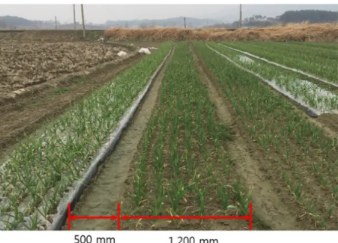
Dimensions of garlic beds
A standard bed size for garlic growing does not exist in Korea. A workable bed size, however, should be defined to design the steering geometries for pivot turning. The most typical bed and furrow sizes were measured, and an example is depicted in Figure 2. The widths of a ridge and a furrow were approximately 1,200 and 500 mm, respectively.
The wheel geometries of the HADA-bot enable a headland turn to be completed in one step. The HADA-bot is optimized not only for a garlic field but also for the majority of upland crops in Asia. In Asia, most upland tool or machinery users consider productivity per land size to be more important than the labor involved. Thus, mini-mizing the furrow width to less than 400 mm is signifi-cant to potential users. Hence, the wheel track (Wt) was
designed to be the same width as the distance of a typical path to the next path. In this study, a total width of 1700 mm (1200 mm for a ridge + 500 mm for a furrow) was set such that the HADA-bot spans across the bed with its wheels in contact with the two furrows (left and right), as shown in Figure 2.
Steering design and kinematics of HADA-bot
For pivot steering, the HADA-bot uses the Ackermann steering geometry with rack and pinion, and tie-rods. Figure 3 shows the Ackermann steering geometry that results in all wheels having their axles arranged as the radii of circles with a typical center point “O.” This arrangement of front steering angles is ideal for slip-freeFigure 1. Scheme of pivot turning on the left rear wheel.
turning with the correct inner and outer wheel speed ratios. This condition is known and used widely as the Ackerman condition, and is expressed as follows:
cot cot (1)
where and are the steering angles of the inner and outer wheels, respectively. The inner and outer wheel angles are defined based on the turning center O.
When the planting robot turns at the headland, the center of the inner rear wheel is on the same turning pivot point as the turning center O in Figure 3. However, unlike conventional steering systems, the turning center of the pivot turning system is located on the inner rear wheel; therefore, a minimum head radius is required. Figure 4 shows the geometry of all the wheels, and the inner and outer wheel angles for pivot turning.
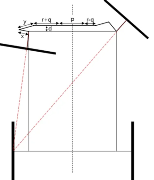
For a steering mathematical model, the rack and pinion Ackermann geometry developed by Koladia (2014) was used in this study. Among several linkages possible for the Ackermann geometry, the rack-and-pinion type was applied because this linkage is the most typical, inexpensive, compact, robust, and simple system that does not require a specialist to maintain, and consists of fewer parts than other linkage types. Nevertheless, it presents inherent disadvantages, such as high friction causing constant wear and more power required to steer. However, from the agricultural equipment perspective, using a rack-and-pinion type mechanism is presents
more advantages than disadvantages to end users. Each variable of the rack and pinion mechanism is defined below:
x = steering arm length y = tie-rod length (in top view) p = rack casing length
r=cylinder rod length L= wheel base
B= distance of left center to right center of steering arm q = travel of the rack
d = distance between front axis and rack center axis β = Ackermann angle (*For this HADA-bot, β= 0
because the pivot point lies at the center of either rear wheel)
From Figure 5, equation (2) can be derived for the tie-rod length:
sin
cos (2) From Figure 6, equation (3) can be derived for the tie-rod length:
sin cos (3)
Figure 4. Geometry of Ackermann turning for a garlic planting robot (top view).
Figure 5. Zero steering angle condition.
From Figure 7, equation (4) can be derived for the tie-rod length:
sin cos (4)Angle is the inner-wheel angle at which the minimum turning angle is defined. From equation (4), the outer-wheel angle can be derived as follows:
cot
cot
(5)Before designing the steering geometry, the given parameters of a purchased steering cylinder and the required pivot steering angles depicted in Figure 6 are defined as below:
p = 420 mm, q = 130.06 mm, r = 237 mm, B = 1314 mm, = 83.15°, = 48.51°, and = 0°
By applying the known parameters to equations (2), (3), and (4), the unknown parameters can be obtained by solving the three equations to satisfy the Ackermann condition when the inner wheel is at an angle , and the outer wheel is at an angle . The unknown parameters are determined (in mm) as follows:
x = 159.52, y = 233.06, and d = 57.40
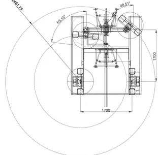
For the pivot steering geometry complying with the Ackermann geometry requirements, the inner front wheel angle was set to 83.15°, and the outer front wheel angle was set to 48.51°. Three different turning radii (as
shown in Figure 8) yield different wheel speed ratios. The wheel speed ratio is equal to the ratios of the turning radii of three wheels. Therefore, the ideal turning speed is determined using the ratios below:
Turning radius of an outer wheel: an inner wheel: an outer rear wheel = 2.46: 1.52: 1.7
Hydraulic system integration
As Choi (2014) suggested, a standard planting dimension is 1,700 mm wide for one path — 500 mm for a furrow and 1200 mm for the ridge; therefore, the HADA- bot shown in Figure 9 was optimized for this standard
Figure 7. Outer-wheel geometry.
Figure 8. Turning radius of each wheel and steering angles for minimum turning radius.
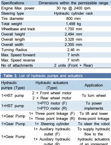
bed size and all systems were fully powered by hydraulic motors and proportional hydrostatic transmission (HST) pumps, which were connected directly to a 30 hp diesel engine. Table 1 shows the specification of HADA-bot. Table 2 shows the list of hydraulic parts used, and Figure 10 shows the hydraulic parts integrated into the HADA-bot.
HADA-bot’s electronic system
To verify the turning radius of the developed steering system for HADA-bot, 20 Hz real-time kinematic global positioning system (RTK-GPS) modules (SMART -6L, Mueller, Salzkotten, Germany) with ±2 cm accuracy, an inclination sensor (NGS2, Sensor-Technik Wiedemann GmbH, Kaufbeuren, Germany), a remote control and receiver (A792, ATECH Co. Ltd., Cheongju-si, Rep. Korea), and a laptop were built into the HADA-bot. As shown in Figure 11, a 32-bit controller (ESX-3XL, Sensor-Technik Wiedemann GmbH, Kaufbeuren, Germany) with the CodeSys structure text programming language was used to mount the actuators and read the sensor signals including the GPS data via IO modules and serial communications. The RTK-GPS was installed at the center between the rear wheels to verify the errors against the theoretical turning radius, and the
Table 1. Baseline specifications of HADA-bot
Specifications Dimensions within the permissible range Engine Max. power 30 hp @ 2400 rpm
Steering type Hydraulic cylinder rack
Tire diameter 800 mm
Total weight 1,498 kg
Wheelbase and track 1,700 mm
Overall height 2,494 mm
Overall length 3,328 mm
Overall width 2,300 mm
Turning Radius 2.46 m
Max. Speed forward 7 km/h Max. Speed reverse 7 km/h No of attachments 2 units (Front + Rear)
Figure 11. Hardware configuration of the HADA-bot system. Figure 10. HADA-bot connections of hydraulic pumps and motors.
Table 2. List of hydraulic pumps and actuators
Hydraulic pumps (Type)
Hydraulic actuators
(Type) Application 1×HST pump 2 × Front wheel motor
2 × Rear wheel motor To turn wheel 1×HST pump 1×PTO motor (F)
1×PTO motor (R)
To power implements 1×Gear Pump 1× Three point linkage (F)
1× Three point linkage (R)
To lift and lower three-point linkage 1×Gear Pump 1× Steering cylinder To steer the robot
1×Gear Pump 1× Auxiliary hydraulic outlet (F) 1× Auxiliary hydraulic outlet (R) To supply hydraulic flow to the hydraulic actuators of an implement
inclination sensor was used to compensate for the sloped terrain causing GPS errors. The remote control and receiver were used to control the HADA-bot’s forward and backward, and left and right steering valves.
Verification of HADA-bot steering system
The analysis of the turning radius of the HADA-bot is required to confirm if it can position itself in front of the next path within an acceptable error. When the platform is not positioned properly along the predefined path, the autonomous system must move forward a certain distance to synchronize its position with the referenced trajectory, which can damage the crops at the head of the row (Nof, 2009).
The maximum angle turning tests focused primarily on analyzing the accuracy for the actual turning radius compared to the designed turning radius. For verifying whether the position of the platform is aligned with the referenced trajectory, the turning radius was compared with a reference radius of 0.85 m. As shown in Figure 12, several tests were conducted in both a farm field and a concrete parking lot located at the HADA Co., Ltd facility. Tests were performed under the maximum steering angle with and without an implement at speeds of 1, 2, and 3 km/h, and included left and right pivot turns at each speed for both concrete and soil surfaces. As shown in Figure 13, a reference circle was used to calculate the RMS errors to analyze the developed steering system, and to examine the differences in the trajectory against those of the reference (Eq. 6).
Definitions of variables:
= center point of the reference circle; = trajectory point;
R = radius of reference circle.
RMS Error =
(6)
Figure 13. Graphical visualization of pivot turning error.
Figure 14. GPS tilt feature on sloped terrain.
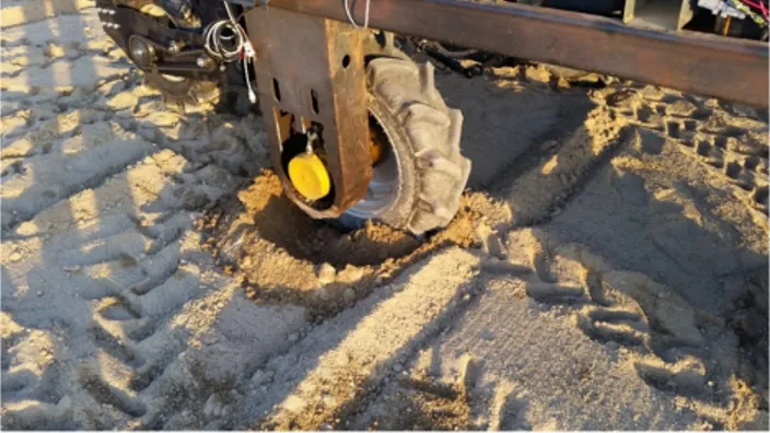
Figure 15. A picture of the HADA-Bot tire digging into ground during causing a 2° to 4° tilt.
Integration of terrain compensation algorithm
Under similar experimental conditions, the analysis for the right and left pivot turning on the soil surface for three speeds of 1, 2, and 3 km/h were conducted with the implemented applied terrain compensation algorithm to compensate for changes in the GPS resulting from the sloped terrain and ground depressions, as shown in Figures 14 and 15. To obtain accurate GPS positions, the error was compensated using the pitch and roll angle values of the gyro sensor mounted on the HADA-bot. The terrain compensation method can be performed using equation (7):
cos sin sin cos sin sin (7) In equation (7),
- α: Roll angle (Positive roll is a tilt to the left)
- θ: Pitch angle (Positive pitch indicates the backward direction)
- ψ: Heading (rad)
- L: Height between ground and GPS receiver - X : Longitude
- Xc: Terrain compensated longitude - Y : Latitude
- Yc: Terrain compensated latitude
Comp arison of headland turning using
HADA-bot against conventional agricultural
vehicles
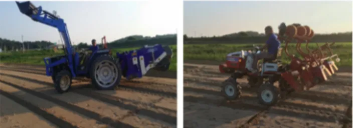
To verify the effectiveness of headland turning as shown in Figure 16, the headland turning time and the required area for a 50 hp tractor (ISEKI, TA5240, Ehime, Japan), a 20 hp cultivator (CFM-1200, Asia Technology, Deagu, Rep. Korea) driven by a skilled driver, and the HADA-bot were compared and analyzed in the soil test field as shown in Figures 17 and 18.
The tests were performed in the same order for the three vehicles as below:
(1) To stop a vehicle or robot at 1.7 m from the end line of a ridge path.
A. The agricultural vehicle was assumed to contain an attachment located 1.7 m from the center of the rear wheels.
B. The same was applied to the HADA-bot.
(2) To start a headland turn by starting a time counter. (3) To place a vehicle adjacent to the next path. (4) To steer back to a straight angle and to unlock the
brake of the pivot-pointed rear wheel (*only applied for HADA-Bot) and record each test time.
Results and Discussion
Turning on concrete surface
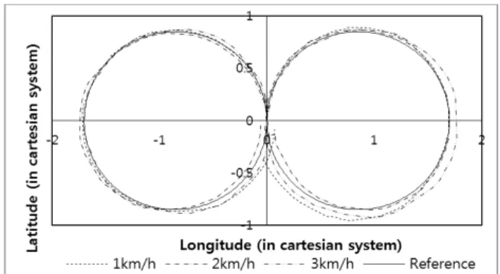
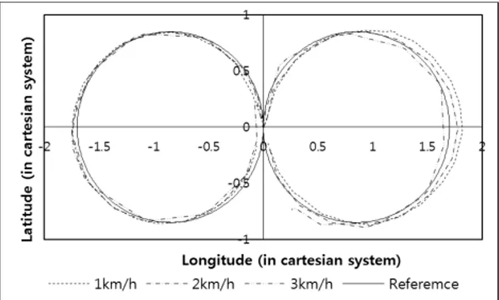
Based on the experimental GPS data pertaining to the HADA-bot while making a pivot turn, graphs were plotted as shown in Figure 19 and Figure 20. Further, we com-pared the diameters of the experimental data turning trajectory, which are circular in shape, with those of the reference circular turning trajectory of 1.7 m diameter (same as the tread-to-tread width of the robot platform) for both left and right pivot turns at three different speeds. The experiments were performed under the maximum steering conditions with and without an implement.
The analytical data for the HADA-bot are shown in
Figure 16. Headland turning path trajectory for HADA-bot test.
Table 3 for both side pivot turning on concrete and soil surfaces at speeds of 1, 2, and 3 km/h. From , for the left and right pivot turns on the concrete surface without and with an implement, the range of RMS errors varies from 2.2 to 5.9 cm which does not include the RTK 2-cm errors. An ideal distance between tires assuming 20-cm tire widths, and the edge of the ridge on either side, is 15 cm. Supposing the worst scenario involving a maximum error of 15 cm, and 2-cm RTK errors at either the left or right side, the RMS errors cannot be larger than 17 cm, which represent 10% of 1,700 mm. From the results, the RMS errors lie within the range of 2.5% to 6.9% and are all less than 10% for either axis, which is an acceptable and favorable condition for headland turning.
The results in Table 3 indicate less than 10% error at all three speeds (1, 2, and 3 km/h) for both left and right turns with or without an attachment. The error for a right turn, however, is 1.9% higher with an implement, and 3.43% higher without an implement than for the left turn error. This may occur because when the steering angle reaches its maximum value, the cylinder rod pushing the steering arm bends in a counter direction to the steering arm. The difference in the rod direction required to reach the maximum steering arm angle in the right turn com-pared to the left turn is a possible reason for the different turning errors. The assembly and welding accuracy may have also contributed to the different errors between the right and left turning angles.
The experimental trajectories are shown in Figures 21 and 22 for pivot turning on the soil surface at a speed of 1, 2, and 3 km/h. From Table 4, for the left and right side pivot turning on the soil surface with an implement, the range of the RMS error varies from 2.5 to 4.8 cm. All the
RMS errors lie within the range of 2.9% to 5.6% and are less than 10% for either axis, which is an acceptable and favorable condition for headland turning. The terrain compensation algorithm improves the error (8 to 17 cm) caused by tilting of 2° to 4° in the soil due to pivot turning (Figure 15).
Figure 18. HADA-Bot headland turn on soil.
Figure 19. Graphical representation of experimental data for left and right pivot turns without an implement at speeds of 1, 2, and 3 km/h on a concrete surface (HADA-bot).
Table 3. Lateral deviation of pivot turning at three speeds on two surfaces with and without an implement (HADA-bot)
Left Turn on Concrete Surface Right Turn on Concrete
Implement Detached Attached Implement Detached Attached
Speed (km/h) RMS Error (cm, (%)) Speed (km/h) RMS Error (cm, (%))
1 3.3, (3.8) 2.8, (3.2) 1 5.4, (6.3) 5.7, (6.7)
2 3.1, (3.6) 2.6, (3.0) 2 2.9, (3.4) 3.5, (4.1)
3 3.0, (3.5) 2.2, (2.5) 3 5.9, (6.9) 5.7, (6.7)
Table 4. Comparison of lateral deviation of pivot turning errors with terrain compensation and without terrain compensation (HADA-bot)
Without terrain compensation Terrain compensation
Left Turn on Soil Right Turn on Soil Left Turn on Soil Right Turn on Soil
Speed (km/h) RMS Error (cm, (%)) RMS Error (cm, (%))
1 6.1, (7.1) 16.0, (18.8) 4.8, (5.64) 3.0, (3.52)
2 10.2, (12.0) 8.0, (9.4) 2.5, (2.94) 2.9, (3.41)
Advantages over conventional vehicles
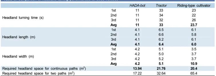
As shown in Figures 23 to 25, for the headland turning tests, the HADA-bot, tractor, and cultivator require 11, 33, and 23.7 s, respectively, at a speed of 2 km/h; further, their maximum headland distance was 4.1 m, 6.8 m, and
6.1 m, as shown in Table 5.
For the headland performance, the HADA-bot achieved much better performance in both required time and space. The HADA-bot reduced 67% in time compared to the conventional tractor, and 54% compared to a riding-type cultivator.
The HADA-bot could perform a headland turn using 36% less headland length compared to a tractor, and 32%
Figure 20. Graphical representation of experimental data for left and right pivot turns with an implement at speeds of 1, 2, and 3 km/h on a concrete surface (HADA-bot).
Figure 21. No terrain compensation applied — graphical representation of experimental data for left and right pivot turns at speeds of 1, 2, and 3 km/h on a soil surface (HADA-bot).
Figure 22. Terrain compensation applied — graphical representation of experimental data for left and right pivot turns at speeds of 1, 2, and 3 km/h on a soil surface (HADA-bot).
Figure 23. Headland turning geometry for a tractor.
Figure 24. Headland turning geometry for a riding-type cultivator.
less compared to a riding-type cultivator. The required space for each vehicle was 13.94 m2, 21.76 m2, and 20.4
m2 for the HADA-bot, tractor, and riding-type cultivator,
respectively. The space difference will affect a farmer’s decision to choose which vehicle to purchase, because this headland space affects their production income.
During the tests, right side pivot turning on the con-crete surface indicated some unusual data once or twice, which can be ignored, as they are beyond the frequency of the experimental data. However, this can be delved further in future studies. In most cases, the percentage of lateral deviation is within the acceptable range of 10%. Occasionally the data obtained are non-synchronized and lack sequence; therefore, accurate projections are difficult to obtain. Hence, HADA-bot experiments are being performed in ongoing research for establishing a correlation between variation in speed and surface con-ditions. For these experiments, a stop-and-go algorithm and a path-following algorithm will be developed. In our next study, a complete auto-guidance with an implement will be developed.
In the headland performance evaluation, the HADA- bot achieved much better performance for both the required time and space. It reduced 67% of the headland turning time compared to the conventional tractor, and 54% compared to a riding-type cultivator. The HADA-bot could perform a headland turn, requiring 36% less headland length compared to a tractor, and 32% less compared to a riding-type cultivator. The required space for each vehicle was 13.94 m2, 21.76 m2, and 20.4 m2 for
the HADA-bot, tractor, and riding-type cultivator, res-pectively. The space difference will affect a farmer’s decision to choose which vehicle to purchase because this
headland space affects their production income.
Conclusions
In this study, an optimized turning mechanism for garlic farming was developed based on a new agricultural robot named the HADA-bot. The HADA-bot achieved a 1.7-m turning radius with the maximum steering angle in either direction to properly align itself with the next path with less effort. The minimized turning time, and proper positioning to the next operating ridge will not only improve upland headland turning efficiency, but will also reduce path tracking errors in autonomous agricultural robots. From the results, the HADA-bot with a self- steering mechanism exhibited a high potential to not only garlic growers but also other upland crop growers.
Conflict of Interest
The authors have no conflicting financial or other interests.
Acknowledgment
This project has been funded by the Korean ministry of trade, industry, and energy (R0004434, 2015-2018), Republic of Korea.
References
Cariou, C., R., Lenain., B., Thuilot, and P., Martinet, 2009. Motion planner and lateral-longitudinal controllers for autonomous maneuvers of a farm vehicle in headland.
Table 5. Comparison of headland turning performances of three vehicles
HADA-bot Tractor Riding-type cultivator Headland turning time (s)
1st 11 33 23 2nd 11 34 22 3rd 11 32 26 Avg 11 33 23.7 Headland length (m) 1st 4.1 6.5 6.1 2nd 4.1 6.6 5.8 3rd 4.1 6.2 6.1 Avg 4.1 6.4 6.0 Headland width (m) 1st 4.2 5.1 3.5 2nd 4.2 5.0 3.7 3rd 4.2 5.2 3.7 Avg 4.2 5.1 10.9
Required headland space for continuous paths (m2) 13.94 21.76 20.4
In : 2009 IEEE/RSJ International Conference on Intelligent Robots and Systems, St. Louis, MO, USA : December 2009.
Choi, Y., I. S. Choi, H. J. Jun, D. K. Choi, T. K. Kang, I. H. Choi. 2014. Analysis of effect for integrated mechanization in garlic production. In : Proceeding of the KSAM 2014 Spring Conference, pp.161-162, Jeonju, Republic of Korea : April 2014
Hague, T. and N. D. Tillett. 1996. Navigation and control of an autonomous horticultural robot. Mechatronics 6(2): 165-180.
https://doi.org/10.1016/0957-4158(95)00070-4 Han, X. Z. 2017. Development of path generation and
robust tracking controller for unmanned tillage tractor in polygonal fields. Unpublished Ph. D. diss. Seoul: Department biosystems engineering, Seoul National University.
Han, X. Z., H. J. Kim, H. C. Moon, H. J. Woo, J. H. Kim and Y. J. Kim. 2013. Development of a path generation and tracking algorithm for a Korean auto-guidance tillage tractor. Journal of Biosystems Engineering 38(1): 1-8. https://doi.org/10.5307/JBE.2013.38.1.001
Han, X. Z., H. J., Kim, J. Y., Kim, S. Y., Yi, H. C., Moon, J. H., Kim and Y. J., Kim, 2015. Path-tracking simulation and field tests for an auto-guidance tillage tractor for a paddy field. Computers and Electronics in Agriculture 112: 161-171.
https://doi.org/10.1016/j.compag.2014.12.025 Koladia, D. 2014. Mathematical model to design rack and
pinion ackermann steering geometry. International
Journal of Scientific & Engineering Research 5(9): 716-720.
KOSIS. 2015. Farm households by harvest area of garlic/ total area. Korean statistical information service. Available at:
http://kosis.kr/statisticsList/statisticsListIndex.do? menuId=M_01_01&vwcd=MT_ZTITLE&parmTabId= M_01_01#SelectStatsBoxDiv
Nof, S. Y. 2009. Springer handbook of automation: Springer Science, New Delhi, India: Springer-Verlag Berlin Heidelberg.
Oksanen, T. and A. Visala, 2004. Optimal control of tractor- trailer system in headlands. In: In : Proceedings of the October 2004 Conference, pp. 1004. Kyoto, Japan: October 2004.
Sabelhaus, D., F. Röben, L. P. Meyer zu Helligen and P. S. Lammers. 2013. Using continuous-curvature paths to generate feasible headland turn manoeuvres. Journal of Biosystems Engineering 116(4): 399-409.
https://doi.org/10.1016/j.biosystemseng.2013.08.012 Xue, J. L. and T. E., Grift. 2011. Agricultural robot turning
in the headland of corn fields. Applied Mechanics and Materials 63-64: 780-784.
https://doi.org/10.4028/www.scientific.net/AMM.63-64.780 Zhang, F. M., B. S. Shin, X. M. Feng, Y. Li and R. J. Shou. 2013.
Development of a prototype of guidance system for rice-transplanter. Journal of Biosystems Engineering 38(4): 255-263.