1. INTRODUCTION
The ram assembly is important equipment in fueling machine of PHWR(Pressurized Heavy Water Reactor) plant where fuel replacement is possible while the plant is in service. The frequent fuel replacement can cause some troubles in the ram assembly that can cause lots of difficulties in power plant operation and maintenance. The ram assembly is typically composed of the B-Ram, the L-Ram and the C-Ram. The B-Ram is focused in this paper because it plays the most important role in the ram assembly. Among the ram fault phenomena, ram stuck phenomena are the most frequent cases in the B-ram. Ram stuck phenomena are due to ball wear and damage in ball nut that increase in proportion to the number of fuel replacement. It is required to predict ram stuck phenomena before they occur. The B-ram has a ball-screw mechanism driven by a hydraulic motor [1]. A ball-screw mechanism has balls, ball screw, and ball nut. With reference to this mechanism, characteristic defect frequency of bearing is used to predict stuck phenomena in this paper.
From all the time-frequency analysis methods, wavelets have been established as the most widespread tool in many areas of signal processing, due to their flexibility and their efficient computational implementation [2]. Discrete wavelet transform is adopted to predict stuck phenomena in this paper because of its superior time-localization properties compared to Fast Fourier Transform.
In this paper, the method to predict ram stuck phenomena is proposed using characteristic defect frequency, frequency bandwidth of coefficients of discrete wavelet decompositions and detail coefficients of discrete wavelet transform with hydraulic motor service outlet port pressure signal. In this paper, ram assembly overview is introduced, and algorithm for predicting ram stuck phenomena is described. Finally the validity of the proposed method is shown via experiment using ball nut characteristic test equipment that simulates ram stuck phenomena due to the increased ball friction in ball nut.
2. RAM ASSEMBLY OVERVIEW
2.1 Ram Assembly
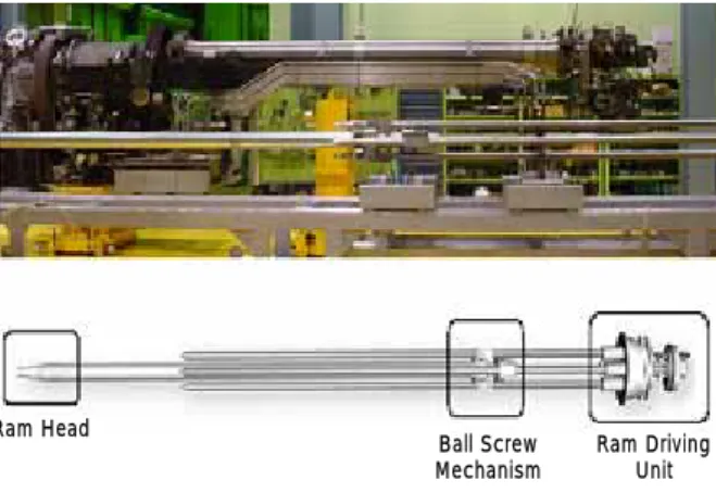
The structure of ram assembly that is focused on in this paper is shown in Fig. 1.
The ram assembly comprises a series of six concentric tubes mounted in a ram housing, and connected to the back of the magazine housing by a clamp and seal ring. The ram assembly installs and removes channel closures and shield plugs into and out of the channel end fittings, operates the snout plug and guide sleeve tool, pushes fuel bundles into the reactor channel and supports the fuel string against channel flow. The six tubes are identified, in order of decreasing diameter, and the B-ram, the L-ram and C-ram. The B-ram and the L-ram are each mechanically driven by hydraulic motors through an oil filled gear box and ball lead screws. The C-ram is operated by pressurized D2O. The L-ram and C-ram
normally move with the B-ram, but can move independently. The ram head consists of a B-ram head, a latch sleeve and a C-ram head, which are mounted on the front of their respective ram tubes and a deflector rod. The B-ram is mechanically driven by a hydraulic motor through reduction gearing and two recirculating ball lead screws [1].
Ball Screw Mechanism
Ram Driving Unit Ram Head
Fig. 1 Ram assembly structure
Application of discrete wavelet transform to prediction
of ram stuck phenomena
Seung-Hyun Byun, Byung-Hak Cho, Chang-Hoon Shin, Joon-Young Park
Power Generaton Laboratory, KEPRI, Daejeon, Korea(Tel : +82-42-865-5392; E-mail: [email protected])
Abstract: The ram assembly is important equipment in fueling machine of PHWR(Pressurized Heavy Water Reactor) plant where fuel replacement is possible while the plant is in service. Troubles in the ram assembly can cause lots of difficulties in power plant operation. The ram assembly is typically composed of the B-ram, the L-Ram and the C-Ram. The B-ram is focused in this paper because it plays the most important role in the ram assembly. Among the ram fault phenomena, ram stuck phenomena are the most frequent cases in the B-ram, which has a ball screw mechanism driven by a hydraulic motor. Ram stuck phenomena are due to ball wear and damage in ball nut that increase in proportion to the number of fuel replacement. It is required to predict ram stuck phenomena before they occur. In this paper, a method is proposed for predicting ram stuck phenomena using a discrete wavelet transform. The discrete wavelet transform provides information on both the time and frequency characteristics of the input signals. The proposed method uses the frequency bandwidths of coefficients of discrete wavelet decompositions and detail coefficients of discrete wavelet transform to predict ram stuck phenomena. The signal used in this paper is a torque-related signal such as a hydraulic service outlet pressure signal in a hydraulic driving system or a current signal in a DC motor driving system. Finally, the validity of the proposed method is shown via experiment using ball nut characteristic test equipment that simulates ram stuck phenomena due to increased ball friction in ball nut.
2.2 Fault cases in the ram assembly
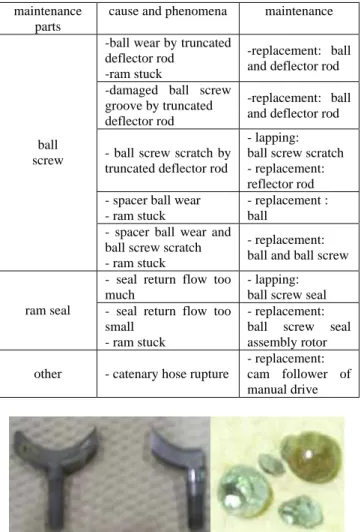
Fault cases in the ram assembly are described in this section. Ram maintenance cases are surveyed, focused on the B-ram, and are summarized in Table 1 categorized by maintenance parts [3]. Table 1 shows that ram stuck phenomena that result from ball wear are the most frequent fault cases. Ball or ball screw scratch due to chips that result from truncated deflector rod and ball wear due to long-term use can cause ram stuck phenomena. Images of damaged deflector rods and balls are shown in Fig 2.
Table 1 Ram fault cases maintenance
parts
cause and phenomena maintenance -ball wear by truncated
deflector rod -ram stuck
-replacement: ball and deflector rod -damaged ball screw
groove by truncated deflector rod
-replacement: ball and deflector rod - ball screw scratch by
truncated deflector rod
- lapping: ball screw scratch - replacement: reflector rod - spacer ball wear
- ram stuck
- replacement : ball
ball screw
- spacer ball wear and ball screw scratch - ram stuck
- replacement: ball and ball screw - seal return flow too
much
- lapping: ball screw seal ram seal - seal return flow too
small - ram stuck
- replacement: ball screw seal assembly rotor other - catenary hose rupture
- replacement: cam follower of manual drive
Fig. 2 Damaged deflector rods and balls
3. DIAGNOSIS ALGORITHM
In case of ram stuck phenomena, torque signal by hydraulic motor that drives the B-ram is increased, that is, the differential pressure between service ports of hydraulic motor is far more increased than that of normal condition. Discrete wavelet transform is used to predict ram stuck phenomena in this paper.
3.1 Wavelet Transform
The wavelet transform is a time-frequency decomposition of a signal onto a set of “wavelet” basis functions. In this section, we review the continuous wavelet transform and the discrete wavelet transform [2][4].
The continuous wavelet transform of a time function s(t) is
given by dt t t s b a W( , )
∫
() *(a,b)() ∞ ∞ − Ψ =(1)
where * denotes complex conjugation and ) ( 1 ) ( ) , ( a b t a t b a − Ψ = Ψ
(2)
is a member of the wavelet basis, derived from the basic analysis wavelet Ψ(t) through translation and dilation. As seen in Eq. (1), the transformed signalW( ba, )is defined on the a - b plane, where a and b are used to adjust the frequency and time location of the wavelet in Eq. (2). A smallaproduces a high frequency wavelet, while a large b produces a low frequency wavelet. The wavelet coefficientW( ba, ) measures the similarity between the signal s(t) and the analyzing waveletΨ(t)at different scales as defined by the parameter a , and different time positions as defined by the parameter b . Eq. (1) indicates that the wavelet analysis is a time-scale analysis. The wavelet transform can be also considered as a special filtering operation. The frequency segmentation is obtained by translation and dilation of the analyzing wavelet. At successively larger scales, the frequency resolution improves and the time resolution decreases.
Discrete methods are required for computerized implementation of the wavelet transform. The discrete wavelet transform is derived from the continuous wavelet transform through discretization of the waveletΨ(a,b)(t). The most common discretization of the wavelet is the dyadic discretization, given by ) 2 2 ( 2 1 ) ( ) , ( j j j k j k t t = Ψ − Ψ
(3)
where a has been replaced by 2 and b by j 2jk. Under
suitable conditions Eq. (3) is an orthonomal basis and the original time function can be expressed as
∑∑
∞ −∞ = ∞ −∞ = Ψ = j k k j k j t C t s() , ( ,)()(4)
dt t t s Cj,k∫
() *(j,k)() ∞ ∞ − Ψ =(5)
whereCj,kare referred to as wavelet coefficients. A second set of basis functionφ(t)called scaling function is then obtained by applying multi-resolution approximations to obtain the orthonormal basis ofΨ(t) : ) 2 2 ( 2 1 ) ( ) , ( j j j k j k t t = φ − φ
(6)
The original time function can now be written as
dt t t f dj,k
∫
() *(j,k)( ) ∞ ∞ − = φ(7)
Here, the dj,k, which are called the scaling coefficients, k
d0, is the sampled version of s(t), represent a j th order
resolution discretization of s(t). The scaling coefficients and the wavelet coefficients for resolutions of order greater than j can be obtained iteratively by
∑
∞ −∞ = + = − i k j k j hi k d d 1, ( 2 ) ,(8)
∑
∞ −∞ = + = − i k j k j g i k d C 1, ( 2 ) ,(9)
The sequences h and g are low-pass and high-pass filters derived from the original analyzing wavelet φ(t)respectively.
The scaling coefficientsdj,k represent the lower frequency
approximations of the original signal, and the wavelet coefficientsCj,krepresent the distribution of successively high
frequencies.
The computation of these filters and their properties have been widely analyzed. The basic step of a fast wavelet decomposition algorithm is illustrated in Fig. 3.
Fig. 3 Basic step of decomposition of the wavelet transform In the decomposition step in Fig 3, the discrete signal S is convolved with a low pass filter L and a high pass filter H, resulting in two vectors cA1 and cD1.
The elements of the vector cA1 are called Approximation
Coefficients and the elements of the vector cD1 are called
Detail Coefficients. The symbol ↓2 denotes downsampling, i.e. omitting the odd indexed elements of the filtered signal, so that the number of the coefficients produced by the basic step is approximately the same as the number of elements of the discrete signal S.
The procedure of the basic step can be repeated on the approximation vector cA1 and successively on every new
approximation vector cAj. This concept is presented by means
of a wavelet tree J levels, where J is the number of iterations of the basic step. In Fig 4, the wavelet tree of a wavelet decomposition for J=2 is illustrated. Each vector Aj includes
approximately, coefficients, where Nt is the length of the
signal s, and provides information about a frequency band [0, Fs/2j+1], where Fs is the sampling rate.
Fig. 4 A two-level wavelet decomposition The reconstruction signals Aj and Dj satisfy the equations:
∑
≤ + = j i i j D A s(10)
where i and j are positive integers.
The adopted wavelet filters determine the quality of the wavelet analysis. In this paper, the Daubechies system of wavelet is used.
3.2 Algorithm for prediction of ram stuck phenomena The proposed algorithm for prediction of ram stuck phenomena in this paper is described as follows.
① Characteristic defect frequency can be computed using
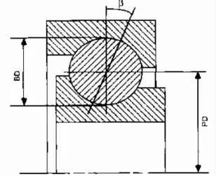
hydraulic motor service outlet pressure signal. Characteristic defect frequency can be calculated using bearing physical characteristics and bearing rotating speed, as shown in Fig 5 [5] : ] cos ) ( 1 [ 2 β BD PD f PD BD fro= r + (11)
wherefrois characteristic defect frequency for defect on roller, BD is roller diameter, PD is bearing pitch diameter, β is contact angle between race and ball.
Fig. 5 Physical structure of bearing
② Pressure signal is decomposed at a level J determined by sampling frequency and characteristic defect frequency computed in ①. Then, detail coefficients at level J, DJ(k) are
produced.
③ The mean m of the absolute values of detail coefficients at level J is computed : N k D m N k J
∑
− = = 1 0 ) ( (12)④ The standard deviationσof the absolute values of detail coefficients at level J is computed :
N m k D N k J
∑
− = − = 1 0 2 ) ) ( ( σ (13)⑤ A threshold TH is computed using the mean and the standard deviation. Detail coefficients below the threshold TH are set to zero and detail coefficients above the threshold TH are set to one.
TH k D if k D TH k D if k D m TH J JTH J JTH ≥ = < = + = ) ( 1 ) ( , ) ( 0 ) ( , 4σ (14)
⑥ Ram stuck phenomena can be predicted in case of detail coefficients above a threshold TH in ⑤.
4. EXPERIMENT
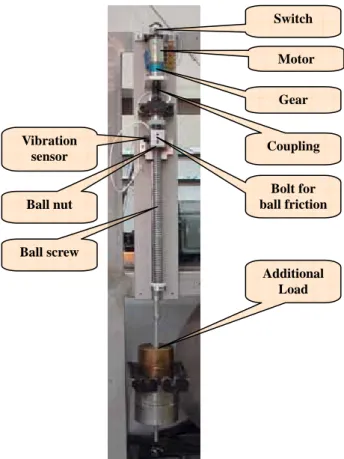
4.1 Experimental setupBall nut characteristic test equipment is set up to simulate ram stuck phenomena by increased ball friction due to ball wear that are the most frequent causes in the ram maintenance
cases. Ball nut characteristic test equipment is shown in Fig. 6. Ball nut characteristic test equipment is driven by a DC motor 3557 K 024 CR078 from MicroMo Electronics. By tightening up bolt for generating ball friction in the deflector and using additional load, friction between balls is increased, and torque data was acquired using PCI-6014 data acquisition card from National Instruments (NI). Data acquisition and analysis program was implemented using Labwindows/CVI from NI.
Fig. 6 Ball nut characteristic test equipment 4.2 Prediction of stuck phenomena
The acquired data is shown in Fig 7 as friction between balls is gradually increased by tightening up bolt for generating ball friction. Fig 7 shows that motor torque is largely increased in case of stuck phenomena, which can be found using root mean square. But prediction of stuck phenomena is more important before stuck phenomena occur.
Fig. 7 Motor torque trend due to increased ball friction It is required to calculate characteristic defect frequency for
predicting stuck phenomena before they occur. Characteristic defect frequency is considered for analysis with the following data : ball diameter = 3mm; pitch diameter = 17.54mm; motor rotating speed by non-contact tachometer = 245rpm; reduction gear ratio = 3.71; contact angle = 0. Characteristic defect frequency by Eq. 10 is calculated to be 6.6Hz. With sampling frequency of 1kHz, frequency bandwidths of approximation and detail coefficients of wavelet decompositions are shown in Fig. 8 [6]. Fig. 8 shows that characteristic defect frequency calculated above corresponds to D7. The torque signal is decomposed up to seven level using Daubechies 2 mother wavelet. Detail coefficients at level 7 calculated by Eq. (12), (13), (14) are shown in Fig 9. Fig 9 shows that signal processing using the algorithm described in the previous section can predict stuck phenomena by detecting discontinuous rotation before they occur.
Fig. 8 Frequency bandwidth of wavelet decompositions
Fig. 9 Detection of discontinuous rotation Motor Switch Coupling Vibration sensor Bolt for ball friction Gear Ball screw Ball nut Additional Load
5. CONCLUSION
In this paper, the algorithm to predict ram stuck phenomena that are the most frequent cases of the B-ram faults in PHWR plant before they occur has been presented. The proposed algorithm uses characteristic defect frequency, frequency bandwidth of wavelet decompositions, detail coefficients of wavelet decompositions. The validity of the proposed prediction algorithm was shown via experiment using test equipment that simulates stuck phenomena by increased ball friction due to ball wear and damaged deflector rod.
REFERENCES
[1] “PHWR Fueling Machine”, wolsong nuclear power site. [2] N.G. Nikolaou, I.A. Antoniadis, “Rolling element
bearing fault diagnosis using wavelet packets”, NDT&E International, Vol. 35, pp. 197-205, 2002.
[3] Byung-Hak Cho, et al., “Development fault diagnosis system for RAM of fueling machine in PHWR plant”, KEPRI, 2004
[4] K. Mori, N. Kasashima, T. Yoshioka, Y. Ueno, “Prediction of spalling a ball bearing by applying the discrete wavelet transform to vibration signals”, Wear, Vol 195, pp. 162-168, 1996
[5] C. James Li, Jun Ma, “Wavelet decomposition of vibration for detection of bearing-localized defects”, NDT&E International, Vol. 30, pp. 143-149, 1997 [6] S. Prabhakar, A.R. Mohanty, A.S Sekhar, “Application
of discrete wavelet transform for detection of ball bearing race faults”, Tribology International, Vol. 35, pp. 793-800, 2002