P2-86 / X. L. Zhu
IMID 2009 DIGEST •
Abstract
We describe a 32” liquid-crystal display (LCD) with multi-touch sensing capability by integrating IR detector arrays onto the LED backlight plate. A transparent light guide is placed in front of the display screen, with IR LEDs disposed at its edges and emitting IR light into the light guide, the light is trapped by total internal reflection within the light guide to be as touch-sensing light. A physical contact with the acrylic plate surface will stimulate some trapped light to be escaped from the light guide and pass through LCD panel to be detected by the IR detectors. The touch-sensing LCD with this configuration can locate simultaneous multiple touché points on the touchable surface.
1. Introduction
Liquid-crystal displays (LCD) have been implemented in a variety of display applications, such as computer displays, personal display assistants (PDAs), kiosks, cell phone displays, etc. Touch sensing displays may allow users to select particular regions on a screen using a variety of input devices, simply by touching that area of the display or placing an object such as a finger, stylus, or pen, etc. in close proximity to that region.
Many touch technologies have been proposed to realize LCD display with touch-sensing capability. Conventional touch technologies include: analog resistive, capacitive, surface acoustic wave (SAW), infrared (IR). These technologies generally have limitations in multi touch [1, 2] or degrading the display performance. Recently, some researchers proposed one approach to achieve LCD display with touch-sensing function is by directly integrating photo sensor arrays into the thin film transistors (TFT) backplane of LCD panel [3, 4]. The photo sensor arrays may sense one or more objects such as a finger
on or above the display screen by detecting the shadow of the ambient light cast by the object or the reflected light from the object which is illuminated by a controlled light source. This kind of photo sensor arrays may have different structures and compose of different materials from LCD TFT backplane. Then, integrating these sensor arrays into TFT backplane will absolutely add fabrication processes, as a result, increase manufacturing expense and the complexity of the display, and also reduce the manufacturing yield of the display. Furthermore, this photo sensor array will reduce aperture ratio of the pixels, affecting the performance of the display. So far, this approach is limited for small size LCD (less than 4.5 inch) display because of the fabrication difficulties.
Therefore, it is desired to achieve a LCD display with multi-touch sensing capability which does not significantly increase the cost and affect the performance of the display. This paper proposes to design a large size LCD display with multi-touch capability. The display comprises of a LCD panel, a LED backlight unit, and a transparent light-guide disposing in front of LCD panel. IR light sources are positioned at the edges of the light-guide to emit IR light into the light guide. The IR light is trapped by total internal reflection within the light guide to be as touch-sensing light. A physical contact with the acrylic plate surface will stimulate some trapped light to be escaped from the light guide and pass through LCD panel to be detected by the IR detectors. The touch-sensing LCD with this configuration can locate simultaneous multiple touch points on the touchable surface. Because only a transparent light-guide is used in front of the LCD panel, there is almost no degradation of the display image.
2. Design
Large-size LCD with touch-sensing capability
X. L. Zhu*, Cass K. M. Sit, Mark W. Ma, Y. J. Feng and K. W. Ng
Applied Science and Technology Research Institute, Hong Kong Science Park, Shatin, NT, Hong Kong
Tel.:852-34062968, E-mail:
[email protected]
Keywords: Multi-touch, IR LED, IR detectorP2-86 / X. L. Zhu
• IMID 2009 DIGEST
2.1 Structure of multi-touch sensing LCD
FIG 1 illustrates a cross-section schematic structure of this multi-touch sensing LCD. The display comprises a LCD panel (LCP) (32” in diagonal), an optical light-guide (LG) (728mm x 418mm) putting in front of LCD panel and a backlight unit (BLU) positioned behind the LCD panel. Here the LG is an 8mm thick transparent acrylic plate. At the each long edge of the light-guide, about 88 IR LEDs with a pitch of 8mm are mounted to emit IR light into the light guide. The IR LEDs have a peak emission at 880nm, with an angle of half intensity of ±200. It is well-known that, total internal reflection will occur in a medium at the boundary with another medium of light-guide and air, if the light incident angles larger than the critical angle c, the light will be total internal reflected and be trapped within the light-guide. The critical angle c is calculated with the Snell’s Law equation: Sinc=1/n. Where n is refractive index of the acrylic plate, about 1.49, so the critical is about 420. In order to efficiently to couple the emitted IR light into the light-guide, the IR LED is positioned with an angle of 200 relative the edge surface of the light guide. The light sources used in the BLU for LCD panel is white LEDs mounting on printed circuit board (PCD), the light further passes through optical films such as diffuser plate and BEF to form a uniform backlight for the image on the LCP to be seen by users.
The IR detectors are uniformly distributed betwee n the LED light sources. In the 32” multi-touch sens ing LCD prototype, 144 detectors are used with a pit ch of about 44 mm. The IR detectors are commercial products capped with IR light filter match the emitt ed IR light. There IR detectors are soldered onto the same PCB as LEDs light source. When a touch obje ct, such as a finger, contacts with the surface of the l ight-guide, the total internal refraction will be frustra ted, some of the trapped light will escape out from t he light-guide as shown in FIG 1. The escaped light passes through LCD panel and optical films. It has b een measured that, ~15% emitted IR light can pass L
CD panel and optical films to be detected by IR dete ctors in back light plate.
2.2 System integration
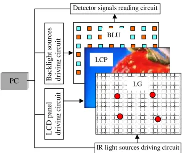
FIG 2 describes the schematic configuration of the multi-touch sensing system. The light intensity of the LED backlight sources and the IR LEDs can be controlled by their driving circuits in accordance with the instruction from the control unit. The sensing signal detecting circuit is controlled by control unit to read signals from the detector arrays and the signals are further processed to locate the touch point positions. The information of the touch position is passed to PC to wait for response. The LCD pixels are controlled to display an image on LCD panel according to the image data provided by PC. The displayed image is updated when the PC is noted by a touch request.
3. Results and discussion
The intensity of the signal received by the touch varies as a function of distance to the touch. As such, touch sensing light detectors, which are laterally closer to the touch object, is expected to receive a stronger intensity light signal than those touch-sensing light detectors with a greater lateral distance away from the touch object. If the detectors have an arrangement as shown in FIG 3 (a), one touch object
Fig.1 Schematic structure of multi-touch sensing LCD display
LG LCP OF IR LED
White LED IR detector PCB
Fig. 2 Schematic configuration of the multi-touch sensing system
LG LCP
BLU
PC
Detector signals reading circuit
Ba c k li g ht s ourc e s d riv in g cir c u it L C D pa ne l d riv in g cir c u it
P2-86 / X. L. Zhu
IMID 2009 DIGEST •
is surrounded by three detectors laterally, these three detectors may have greater signal values than other detectors. As shown in FIG 3 (a), Ta and Tb are two
touch points from the light-guide surface, projected onto the IR detector arrays. FIG 3 (b) shows the corresponding signals of the detectors. The read signals from the IR detectors are further processed to locate the touch positions.
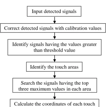
FIG 4 is the flow chart describes how the detected signals are processed to locate the touch positions. Firstly, the detected signals are input into the signal processing unit. These input signals are then corrected with the calibration values which are pre-set for each detector base on a level of white noise and non-uniform sensitivity for each detector. The corrected signals are compared with the threshold value to delete the noise from the signals. The signals larger
than the threshold are further used to identify the touch areas with an edge detection method. Within each area, the signals with the top three maximum values are searched out and are used to calculate the coordinates of the touch in this area. Finally the touch coordinates information is output to PC to wait for response. Currently, the touch position coordinate is simply calculated with the signal values of the three detectors surrounding the touch. With this algorithm, the accuracy of the calculation is very poor. In order to accurate locate the touch position, the profile of the IR light illumination on the IR detectors should be considered. So the signal process method and touch coordinate calculation algorithm are needed to be further optimized in the future work.
FIG 5 (a) and (b) show the measured signal map of detector array with one touch input and two
Fig. 4 Signal processing steps to locate touch positions
Input detected signals
Correct detected signals with calibration values
Identify signals having the values greater than threshold value
Identify the touch areas
Calculate the coordinates of each touch Search the signals having the top three maximum values in each area
Fig. 5 Measured signal map of detector array with one touch input (a) and two simultaneous
touch inputs Fig. 3 (a) Top-view of IR detectors array with two
touch points; (b) corresponding signals from the IR detectors.
Ta
Tb
P2-86 / X. L. Zhu
• IMID 2009 DIGEST
simultaneous touch inputs, respectively. One peak can be observed when only one touch input on the touchable surface, while when there are two touch inputs, the signal map will give two peaks, with the two peaks, the positions of the two touch points can be calculated.
4. Summary
A 32” LCD display with multi-touch sensing capability is realized. IR light detector arrays are putting onto the LED backlight plate to detect the IR light escaped out of a light guide when an object stimulates a touch on the touchable surface. The multi-touch sensing display can recognize and locate simultaneous multiple touch points.
Acknowledgement
This work was supported by the innovation and technology fund from Hong Kong government.
5. References
[1] S. H. Bae, B. C. Yu, S. Lee, H. U. Jang and et al. SID Technical Digest, pp.178-181(2008).
[2] J. Y. Han, ACM UIST, pp. 115-118 (2005). [3] W. D. Boer, A. Abileah, P. Green, T. Larsson, S.
Robinson and T. Nguyen, SID Technical Digest, pp.1494-1497(2003).
[4] J. H. Lee, J. W. Park, D. J. Jung, S. J. Park and et al., SID Technical Digest, pp.1101-1104 (2007).