1. INTRODUCTION
Recently the rehabilitation engineering to restore physical abilities is regarded as an important technology for improving the quality of life. As the silver generation has been exponentially increasing, the social demands for the assistive devices such as prosthetic and orthotic devices to assist the muscle power are also increasing linearly. Most assistive devices use an electro-mechanical system like the electric motor for the assist force. However such power-assist system is heavy and not compatible with the human muscular system. Therefore an artificial muscle to be implantable in human body is needed for the bio-mimetic power assistive system.
The electro-active polymer (EAP) was proposed as an artificial muscle to substitute for the human muscle [1]. Especially, ionic polymer metal composite (IPMC) is widely applying to the artificial muscle because it is simply manufactured and is driven by relatively low input voltage [2, 3]. The IPMC bends to the anode side when subjected to a voltage across its thickness as a result of cation migration toward cathode in the polymer network, because the cathode side of the composite swells and the anode side of it shrinks by the electro-osmotic drag of water induced by the cation migration [4]. The IPMC usually consists of a thin polymer membrane with metal electrodes plated chemically on both faces. Therefore, the IPMC has a wide usability in the soft robotic actuator and the dynamic sensors, because it can be utilized as an actuator module [1, 2, 5].
This study proposes an IPMC actuating system with a biomimetic function. The IPMC module is actuated by the human EMG signals generated by an intended muscle contraction. In this study, two muscles in forearm are used for the actuation of the IPMC. To obtain higher actuation force of the IPMC, the single layered as thick as 800 [µm] or multi-layered IPMC (Nafion) of which each layer can be as thick as 178 [µm] were prepared. To preserve the water existing within the IPMC for longer life performance, the each IPMC layer was coated and protected on the surface with some selected coating materials.
To investigate the IPMC actuation behaviors controlled with EMG signals [6, 7] generated from the human flexor carpi ulnaris and extensor carpi ulnaris muscles, we implemented an IPMC control system. The experimental results showed a possibility and a usability of the bio-mimetic artificial muscle.
2. EMG SIGNAL
EMG signal is the measured electric potentials produced by
voluntary contraction of muscle fiber. The frequency range of the EMG signal is within 0 to 2,000 [Hz] but the dominant energy is concentrated in the 30 to 500 [Hz] ranges, and its amplitude is limited to 0 to 10 [mV] (peak-to-peak) according to the muscle contraction [8]. Consequently, the muscle activation can be detected by measuring the amplitude of the EMG signal, because the amplitude of the EMG signal increases according to the increase of the muscle contraction force [7]. In this study, we apply the mean absolute value (MAV) of the surface EMG signal to the detection of the muscle activation.
Myoelectric
MyoelectricSensor CircuitSensor Circuit
MAV signal
Myoelectric signal
+ -G
diff. amp with BPF
Ref. MAV circuit BPF 32dB out V line V V2+ line r V V+ line V V1+ Hz wo=60 Hz w 41= Hz w2=900 o w 1 w w2 VR BRF G 60dB o w electrode AC coupled Amp clamper peak det. integrator Hz wo=60 Line noise Myoelectric
MyoelectricSensor CircuitSensor Circuit
MAV signal
Myoelectric signal
+ -G
diff. amp with BPF
Ref. MAV circuit BPF 32dB out V line V V2+ line r V V+ line V V1+ Hz wo=60 Hz w 41= Hz w2=900 o w 1 w w2 VR BRF G 60dB o w electrode AC coupled Amp clamper peak det. integrator Hz wo=60 Line noise
Fig. 1 Block diagram of EMG electrode
(a) EMG signal
(b) MAV signal
Fig. 2 Example of the EMG and the corresponding MAV signals.
Actuation of Artificial Muscle Based on IPMC
by Electromyography (EMG) Signal
Myoung-Joon Lee, Sung-Hee Jung, Inhyuk Moon, Suk-Min Lee, and Mu-Sung Mun Korea Orthopedics and Rehabilitation Engineering Center, Incheon, Korea
(Tel : +82-32-500-0576; E-mail: [email protected])
Abstract: This paper proposes an IPMC actuating system with a bio-mimetic function. EMG signals generated by an intended
contraction of muscles in forearm are used for the actuation of the IPMC. To obtain higher actuation force of the IPMC, the single layered as thick as 800 [µm] or multi-layered IPMC (Nafion) of which each layer can be as thick as 178 [µm] are prepared. The experimental results using an implemented IPMC control system show a possibility and a usability of the bio-mimetic artificial muscle.
Fig. 1 shows the block diagram of the surface EMG sensor used for measuring the MAV signal. The electric potentials obtained from two input electrodes are first amplified. The differential amplifier includes a band pass filter (BPF) with 4 [Hz] to 900 [Hz] bandwidths to select the EMG signal only, and its output signal is the raw EMG signal. However, 60 [Hz] noise due to the AC power line is mixed in the raw EMG signal. Therefore, we apply the band rejection filter (BRF) to the raw EMG signal. Since the passive filter attenuates the source signal, we then amplify the output of the BRF using AC-coupled amplifier with 60 [dB] gains. To adjust the difference of the source signal due to the muscle condition, we make a variable resistor in the input of the AC-coupled amplifier. Using a MAV circuit designed by a clamp and a peak detector circuit, the MAV signal with ripple is generated. Then, the final output is smoothed by a LPF with 1 [kHz] cutoff frequency.
The MAV signals corresponding to the raw EMG signals show in Fig. 2.
3. IPMC
3.1 Actuation principle of IPMC
The IPMC is composed of a perfluorinated ionic polymer, which is chemically surface composited with a conductive medium such as platinum. A platinum layer is formed a few
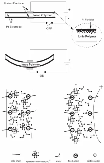
Fig. 3 A schematic diagram of the typical IPMC artificial muscle and its actuation principle.
Fig. 4 Schematic diagram of IBAD
microns deep within the perfluorinated ionic polymer. Typically, the strip of the perfluorinated ionic polymer membrane bends toward the anode (in the case of cation exchange membranes) under the influence of an electric potential. Also, the appearance of water on the surface of the expansion side and the disappearance of water on the surface of the contraction side are common. This electrophoresis-like internal ion–water movement is responsible for creating effective strains for actuation. Water leakage through the porous Pt electrode reduces the electromechanical conversion efficiency [2].
3.2 Preparation of IPMC
The actuation efficiency of IPMC depends on various factors including types of polymer membrane and electrode, the type of cation, the plating condition, the morphology and conductivity of the metal electrodes, surface roughening treatment, and the level of hydration [9]. As a very important factor among them, the electric property of surface electrode is mainly influenced by the molecular configuration of surface and membrane-metal interface.
In this study, the IPMC was prepared by adsorption- reduction method using Nafion 117 (H+-form, EW 1100,
Dupont) and solution of platinum complex ([Pt(NH3)4Cl2], Aldrich Co.) [3]. The Ion Beam Assisted Deposition (IBAD) was adopted for surface electrode fabrication. After IPMC specimen set up in cyclic holder, the deposition of novel metals (Pt, Ir, and Au) was conducted on the surface of IPMC by electric gun (Telemark, USA) at acceleration voltage of 8.5 [kV] and deposition rate of 0.1 [Å/sec], sustaining in vacuum of ~5×10⁻⁶ [Torr]. Fig. 4 shows the schematic diagram of
IBAD.
(a)
(b)
Fig. 5 Scanning electron microscopy (SEM) morphology and 3D-profiler of the IPMCs plated by (a) chemical reduction and
10 15 20 25 30 0 10 20 30 40 50 S u rf a ce Re si st a n ce ( Ω ) Distance(mm) Chemical reduction IBAD
Fig. 6 Electric surface resistance of surface electrode of IPMCs with Pt plated by chemical reduction and by IBAD
The sandblasted Nafion was made into IPMC by adsorption-reduction method as initial compositing, and then surface electroding was carried out by conventional chemical reduction for comparison as well as IBAD method adopted in this study. Fig. 5 shows surface roughness and morphology of surface electrode of IPMC prepared by those two methods. Fig. 5 (a) shows the surface of IPMC plated with Pt by chemical reduction and (b) is the surface of IPMC plated by physical IBAD method.
The surface roughness was ranged 0.4 [µm] by IBAD deposition, which indicates that the platinum layer became smoother and more homogeneous than conventional chemical reduction method. The effect of improved surface property could be reflected in electro-mechanical actuation performance of IPMC. Fig. 6 shows the surface resistance of surface electrodes prepared by two processes. The surface electric resistance of chemically plated IPMC increases noticeably from 20 to 40 [Ω] along the IPMC strip, while the surface electrode by IBAD show as small as 8 [Ω] at end point and its slope along the strip is relatively quite low.
chemical reduction IBAD-Pt IBAD-Au IBAD-Ir
0.0 0.5 1.0 1.5 2.0 2.5 3.0 3.5 4.0 4.5 5.0 M ax. D isp .( m m )
Kind of surface electrode (a) 0 500 1000 1500 2000 2500 0.0 0.5 1.0 1.5 2.0 2.5 3.0 Time(ms) D ispl acem ent (m m ) chemical reduction IBAD-Pt IBAD-Au IBAD-Ir (b)
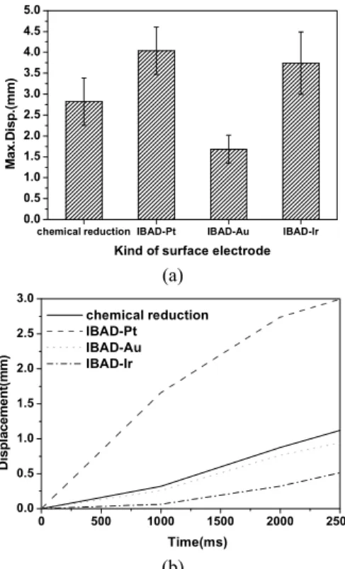
Fig. 7 Maximum displacement (a) and initial displacement (b) of IPMCs plated by chemical reaction (Pt) and IPMCs plated with different novel metals by IBAD for surface electroding.
3.3 Actuation characterization
IPMC with surface electrode made of precious metals such as Pt, Ir, and Au by IBAD were also prepared for comparison study. The electro-mechanical displacement and force of several IPMCs with different metal as surface electrode were measured. Cu and silver were also tried by IBAD deposition and was not proper as surface electrode due to their active reactivity in hydration condition. The thickness of Pt, Ir, and Au deposited on the surface of IPMC were approx. 500 [Å]. Fig. 7(a) and (b) shows the maximum displacement of the IPMCs and the initial actuation behaviors of the IPMCs according to induction time for 3 [min], respectively, when the voltage of 2 [V] DC was applied on the both faces of the IPMCs. The sample by chemical reduction (Pt) was also shown for comparison purpose. The displacement of IPMC plated with Pt by IBAD shows the greatest displacement among samples investigated. The Pt plating by IBAD endows the IPMC with rapidest reaction to displacement.
Fig. 8 shows the long time displacements of IPMCs plated with Pt through chemical reduction and by IBAD under electric voltage of 2 [V] DC in order to observe the back bending effect of IPMC. The mechanism of actuation IPMC is basically that hydrated cations move from anode toward cathode by electric stimuli. The composite in hydrated state performs an oscillatory bending motion when an alternating voltage is imposed across its faces. When constant voltage (DC) is applied across the faces of IPMC suddenly, an initial quick bending towards the anode is generally followed by a slow relaxation in the reverse direction towards the cathode [9-12]. The reasons of the relaxation can be electro-osmosis and transport of hydration cation. Chemically plated surface electrode shows the more relaxation in the reverse direction, as shown in Fig. 8. On the other hand, a smoother and more homogeneous surface electrode imposed by IBAD appears to retard the relaxation definitely.
Fig. 9 shows the actuation behaviors of IPMCs plated with Pt by chemical reduction and IBAD method, when the IPMCs were applied under voltage of 3 [V] AC at 0.1 [Hz] for 30 [sec]. The 0.1 [Hz] as frequency for AC voltage was chosen, because IPMCs showed the maximum displacement and force during the initial actuation for 30 [sec]. The higher displacement and force of the IPMCs by IBAD is attributed to the effect of improved surface electroding. The maximum force of surface electrode by IBAD was over 1.0 [gf], while chemically plated composite was 0.8 [gf]. It was presumed partly due to the mechanical strength of composite increased by more homogeneous surface electrode, and the surface electrode density can be presumed as one of the factors for high actuating force of IPMC.
0 5000 10000 15000 20000 25000 3000 0 1 2 3 4 5 Di spl aceme n t( mm ) Tim e(m s)
C hem ical reduction
IBA D
Fig. 8 Displacement of IPMC plated with Pt by chemical reduction (solid line) and by IBAD (dot line)
2.0 2.5 3.0 0 1 2 3 4 5 6 7 8 9 10 M ax. D isp. (m m ) Voltage(V) Chemical reduction IBAD (a) 2.0 2.5 3.0 0.0 0.2 0.4 0.6 0.8 1.0 1.2 Fo rc e( gf ) Voltage(V) Chemical reduction IBAD (b)
Fig. 9 Maximum displacement (a) and force (b) of the IPMC plated with Pt by chemical reduction and by IBAD as surface
electroding
3.4 IPMC for artificial muscle
We used two types of Nafion membrane with different thickness for artificial muscle. Thin membrane of which thickness is about 178 [µm] was Nafion 117 (DuPont). Another thicker Nafion membrane was obtained by the solidification of Nafion solution (SE-10072, DuPont) at 80 [℃] followed by the evaporation at 150 [℃] to remove completely the Dimethyl formaldehyde (DMF) [13]. The thickness of the membrane was about 800 [µm]. For long-term actuation performance, each IPMC layer was coated and protected on the surface with selected chemical coat material.
We prepared three types of IPMC actuators;
#1. IPMC specimen A (single layer, thickness: 178 [µm]) #2. IPMC specimen B (single layer, thickness: 800 [µm]) #3. IPMC specimen C (3 layer lamination, each layer’s thickness: 178 [µm])
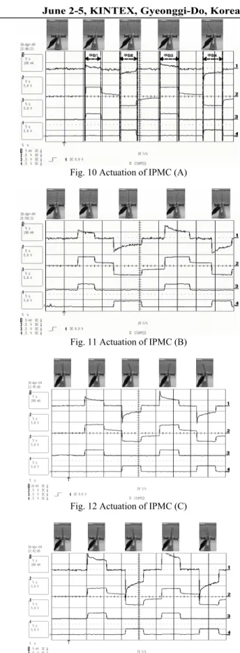
Figures 10 to 13 show the actuation results of different IPMC samples. In each figure, the channel 1 indicates the electric current, and the channel 2 is the voltage. The channel 3 and 4 are control signals, respectively. Upper images show the configurations of IPMC actuators in each period. The x axis is time scale in which each period is 5 [sec]. The y axes of the 2, 3 and 4 channels are voltage scale (each period is 5 [V]), but that of 1 channel is current scale, (each period is 100 [mA], and it is 200 [mA] for figure 12.) Table 1 show the displacements of each period and average displacement, when each period is assigned 1 to 4 in sequence.
Table 1 Displacements of IPMC
period 1~2 period 3~4 average displacement IPMC (A) 30 [mm] 31 [mm] 30.5 [mm] IPMC (B) 6 [mm] 6 [mm] 6 [mm] IPMC (C) 13 [mm] 11 [mm] 12 [mm] IPMC (C*) 18 [mm] 20 [mm] 19 [mm] (*IPMC (C) changed in sequence of layers )
Fig. 10 Actuation of IPMC (A)
Fig. 11 Actuation of IPMC (B)
Fig. 12 Actuation of IPMC (C)
Fig. 13 Actuation of IPMC (C) changed in sequence of layers When the power supply is shut from the IPMC actuators, the voltage imposed on the IPMC is found to decrease from 2 to 0 [V] gradually, since it carries the characteristic of a capacitor.
Fig. 14 Example of motion classification method by the movements of flexor carpi ulnaris and extensor carpi ulnaris
using a threshold
4. ACTUATION OF IPMC BY EMG SIGNALS In this study, we confirmed that the IPMC actuation can be controlled by human EMG signals, and it is considered as one of the essential features for biomimetic functions of IPMC for an application of artificial muscle. We first define the applied power polarities on both sides of IPMC to control the bending motions using EMG signals generated from the human flexor carpi ulnaris and extensor carpi ulnaris muscles. Muscle movements are recognized by comparing MAV signal with a threshold value. Fig. 14 shows an example of motion classification method by the movements of flexor carpi ulnaris and extensor carpi ulnaris using a threshold. ‘On’ and ‘off’ mean whether the muscle movement is valid or not. Table 2 shows the muscle movement, corresponding states and applied power polarities. When extension motion is occurred, the applied power polarities on side A is (-) and the applied power polarities on side B is (+). When flexion motion is occurred, the applied power polarities on side A is (+) and the applied power polarities on side B is (-). If no valid motion is occurred, the power is not applied.
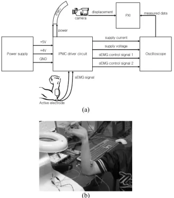
Figure 15 shows the Actuation scheme of IPMC actuation controlled by EMG signals and its real image. Electric field and current imposed on the two faces of IPMC and two EMG
IPMC driver circuit
IPM C Power supply GND +5V +4V Oscilloscope supply current supply voltage sEMG control signal 1 sEMG control signal 2
PXI measured data
power camera displacement Active electrode sEMG signal (a) (b)
Fig. 15 Actuation scheme of IPMC actuation controlled by EMG signals (a) and its real image (b)
Table 2 Truth table of the power polarity on both sides of IPMC
polarity flexor
MAV
extensor
MAV state side A side B
off off none none none
off on extension (-) (+)
on off flexion (+) (-)
on on none none none
signals entering the IPMC driver circuit was measured with an oscilloscope (LeCroy 9354 TM). The measured data were transferred to PXI (PCI eXtensions for Instrumentation) using GPIB protocol. Real images of IPMC actuation captured with CCD camera were collected through PXI image collecting board (NI-1409).
The electric voltage imposed on IPMC was designed to change in a linear relation with the detected EMG signals, and thus the bending movement of IPMC is controlled linearly according to that of the wrist, as a real image of the actuation is shown in Figure 16. Four strips shown in the figure were used to imitate the four fingers of human hands except thumb. The electric field and current imposed on the two faces of IPMC and two EMG signals entering the IPMC driver circuit were measured with an oscilloscope for analysis. Figure 18 shows the actuation data of IPMC using EMG signals generated from the human flexor carpi ulnaris and extensor carpi ulnaris muscles. The channel 3 and 4 are detected EMG signals, respectively. When the oversized voltage is applied on
(a) (b)
Fig. 16 Actuation of IPMC by EMG signal in none state (a) and flexion state (b)
Fig. 18 Actuation of IPMC using EMG signals generated from the human flexor carpi ulnaris and extensor carpi ulnaris
the IPMC, the IPMC driver circuit we designed limits the voltage imposed on the IPMC in order to prevent the abrupt physio-chemical change of the IMPC nature and subsequent shortening of the actuation operating time of the IPMC, as shown in the data for the channel 2 of Figure 18.
5. CONCLUSION
This paper proposed an IPMC actuating system with a bio-mimetic function. EMG signals generated by an intended contraction of muscles in forearm were used for the actuation of the IPMC. To obtain higher actuation force of the IPMC, the single layered as thick as 800 [µm] or multi-layered IPMC (Nafion) of which each layer can be as thick as 178 [µm] were prepared. To preserve the water existing within the IPMC for longer life performance, the each IPMC layer was coated and protected on the surface with some selected coating materials. To preserve the water existing within the IPMC for longer life performance, the each IPMC layer was coated and protected on the surface with some selected coating materials. It was successfully demonstrated that the IPMC actuation could be controlled efficiently with EMG signals generated from the human flexor carpi ulnaris and extensor carpi ulnaris muscles. We also found out that the IPMC system can be implemented to confirm a possibility and a usability of the bio-mimetic artificial muscle controlled by human bio-signals.
In the future, we will focus on developing a biomimetic actuating system which can be used for the assistive devices by prosthetics and orthotics to assist the human muscle power in order to replace an electro-mechanical system like electric motors in the application field of rehabilitation technology and engineering.
ACKNOWLEDGMENTS
This study was supported by a grant of the Korea Health 21 R&D Project, Ministry of Health & Welfare, Republic of Korea. (02-PJ3-PG6-EV03-0004)
REFERENCES
[1] Y. Bar-Cohen, Electroactive Polymer (EAP) Actuators as Artificial muscles: Reality, Potential, and Challenges, SPIE Press, Bellingham, WA, 2001.
[2] M. Shahinpoor and K. J. Kim, “Ionic Polymer-Metal Composites: I. Fundamentals,” Smart Material and Structure, Vol. 10, pp. 819-833, 2001.
[3] Y. Abe, A. Mochizuki, T. Kawashima, S. Yamashita, K. Asaka and H. Takenaka, “Bending of Polyelectrolyte Membrane-Platinum Composites by Electric Stimuli I. Response Characteristics to Various Waveforms,” Polymer Journal, Vol. 27, No. 4, pp. 436-440, 1995. [4] K. Asaka, K. Oguro, Y. Nishimura, M. Mizuhata and H.
Takenaka, “Bending of Polyelectrolyte Membrane- Platinum Composites by Electric Stimuli I. Response Characteristics to various Waveforms,” Polymer Journal, Vol. 27, No. 4, pp. 436-440 , 1995.
[5] M. Shahinpoor and K. J. Kim, “The effect of surface-electrode resistance on the performance of ionic polymer-metal composite (IPMC) artificial muscles,” Smart Material and Structure, Vol. 9, pp. 543-551, 2000.
[6] T. Moritani and Y. Yoshitake, “The Use of Electromyography in Applied Physiology,” Journal of Electromyography and Kinesiology, Vol. 8, pp. 363-381, 1998.
[7] C. J. De Luca, “The use of surface electromyography in biomechanics,” Journal of Applied biomechanics, Vol. 13, pp. 135-163, 1997.
[8] Carlo J. De Luca, "Surface Electromyography: Detection and Recording", Delsys Incorporated, 2002.
[9] K. Onishi, S. Sewa, K. Asaka, N. Fujiwara and K. Oguro, “Morphology of electrodes and bending response of the polymer electrolyte actuator,” Electrochimica Acta, Vol. 46, pp. 737-743, 2000.
[10] S. Nemat-Nasser, “Micromechanics of Actuation of Ionic Polymer-metal Composites,” Journal of applied Physics, Vol. 92, pp. 1-21, 2001.
[11] M. Uchida, C. Xu, M. L. Guilly and M. Taya, “Design of Nafion Actuator with Enhanced Displacement,” Proc. SPIE, Vol. 4695, pp. 57-66, 2002.
[12] J. H. Lee, J. D. Nam, H. Choi, K. Jung, J. W. Jeon, Y. K. Lee, K. J. Kim and Y. Tak, “Water uptake and migration effects of electroactive ion-exchange polymer metal composite(IPMC) actuator,” Sensors and Actuator, Vol. 118, pp. 98-106, 2004.
[13] K. J. Kim and M. Shahinpoor, “A Novel Method of Manufacturing Three-Dimensional Ionic Polymer-Metal Composites (IPMC’s) Biomimetic Sensors, Actuators and Artificial Muscle,” Polymer, Vol. 43, No. 3, pp. 797-802, 2002.