42-3 / H. Li
• IMID 2009 DIGEST
Abstract
A volumetric 3D display system based on a rotating two dimensional color LED array is set up. It has a cylinder display space Φ800×640mm3 which is composed of 256 slices of pictures in one 3D image with each slice 320×256 LED pixels. The volumetric image has 4 gray scales and 64 colors. The main structure and working principle of the system is described in detail.
1. Introduction
Volumetric display is a kind of technology to presents 3D scenes to multiple individuals who view from different directions. The realization technology of this kind of display can be in several ways. One is holographic displays which reproduce a 3D light field with the same intensity, phase and transmit direction as that from the real object by diffraction of light from a holographic pattern [1]. Another technology is to sweep a time-varying 2D image through a 3D spatial volume at a higher frequency than the human eye can resolve. It can be realized by sweeping a screen mechanically on which a series of images is displayed [2][3], or by sweeping a laser beam in a 3D photoluminescence medium[4]. These display systems show the 3D scene in 360 degrees.
In order to get high spatial resolution and stable volumetric 3D picture, a high frame rate image generator is usually needed in swept-volume volumetric display systems. One of these generators is the DMD device which is used in data projectors. Another one is LED screen whose response time can reach tens of nanoseconds. Here we present a color large volumetric display system based on a rotating two-dimensional LED array which has a cylinder
display space Φ800×640mm3 with 256 slices of
pictures in one 3D image and 320×256 pixels in per slice.
2. System Configuration
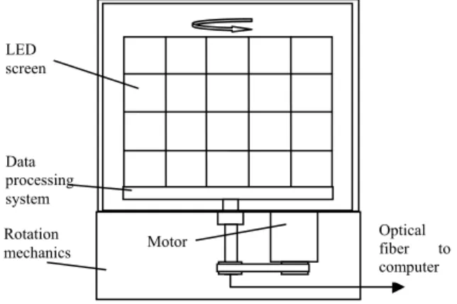
The system is composed of three parts: the LED screen, the date processing system and the rotation mechanics, as shown in Fig.1. The LED screen consists of 20 sub-LED panels each of which has 64(horizontal)×64(vertical) pieces of three-color LED(R,G,B) arranged in pitch size 2.5mm. The panels are arranged in 4 lines and 5 columns so that the screen has the total resolution of 320×256 pixels with the screen area about 800mm×650mm. The rotation mechanics enable the screen to rotate about 900rpm to form a cylinder volumetric 3D image. The electric power is transmitted through 2 electric slip rings to the LED panels which has the maximum power consumption about 800 Watt. The data processing system is rotated with the LED screen. The display signal from computer is transmitted by optical fiber and a fiber optic rotary joint to the data processing system. Rotation mechanics LED screen Data processing system Optical fiber to computer Motor
Fig. 1. The schematic diagram of the LED volumetric display system
Color volumetric 3D display system based on
a rotating LED Screen
Li Haifeng, Wu Jiang,Liu Xu, Yan Caijie,Zheng Zhenrong
State Key Laboratory of Modern Optical Instrumentation, Zhejiang University, Hangzhou 310027, China
TEL:86-571-87951576, e-mail: [email protected] Keywords : Volumetric display, 3D display, Color LED
42-3 / H. Li
IMID 2009 DIGEST •
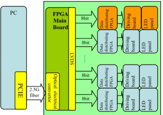
The structure of the data processing system is shown in Fig.2. The volumetric image data generated in a computer is converted to optical signal by a PCIE card and transmitted in a 2.5G fiber. The image data is then received by an optical electrical converter in the data processing system. After segmented to 20 sub-images, the image data is distributed to 20 data distribution FPGA boards separately by the FPGA main board. Because the image displayed on the screen should be correspond to the position of the screen in rotation, each sub-image data received by the data distribution FPGA board is stored in a DDR RAM first, and write to the driving board later in proper time.
The LED driver is composed of 20 sub driver boards, each of which is connected to its corresponding sub LED panel. All the panels are working in parallel. In each panel, every 16 columns of the LED pixels are addressed in progressive scanning method. The system is designed to display 30 volumetric frames per second. For one turn the screen scan the cylinder space twice, the rotation speed is 15rps. The scan time for every column is 1/(256×30××16) = 8.138 µs. Because the time for the LED driver IC receiving the driving data is about 1.5µs, the time left for LED lighting is about 6.6µs. The gray scale of the LED screen is obtained by PWM(pulse width modulation) method. For the long response time of the commercial LED driving IC, large amount of gray scales can not be obtained. Here we encode the gray scales in 2bits which gives 4 gray scales. The lighting time of LED for each gray scale is shown in table 1. The maximum numbers of the color now obtained is 64.
Table 1 The gray scale and LED lighting time
Bit of gray scale Light time(µs)
00 0 01 2.2 10 4.4 11 6.6
3. Results and discussion
The system and the volumetric image displayed are shown in Fig.3 and Fig.4 respectively. The whole volumetric 3D image is composed of 256×2 slices of images in one turn. The screen rotation speed is about 900rpm. Because the gray scale can be separated into different numbers of individual light pulse, the number of the slices can be 3 times larger if the system only shows the binary 3D images.
Fig.3. The LED volumetric display system
Fig . 4 . The displayed volumetric image of the system PC PCIE FPGA Main Board 2.5G fiber 8bit 8bit ... 8bit 8bit Da ta dis tr ibut ing
FPGA Driving boar
d LED panel Da ta dis tr ibut ing
FPGA Driving board LED panel
Da ta dis tr ibut ing
FPGA Driving boar
d LED panel Da ta dis tr ibut ing
FPGA Driving board LED panel
LVDS
Optical elec
trical
convertor
Fig. 2. The schematic diagram of the data processing system
42-3 / H. Li
• IMID 2009 DIGEST
The total voxels in the volumetric 3D image can be calculated by multiplication of the number of slices and the LED pixels of the screen. It is about 63M for red, green and blue voxels in this system. The data quantity of the image for one rotation is about 0.25G. If the refresh rate of the image is 15f/s, the image data flow will be 3.75Gbits/s which is larger than the data transmission rate of the fiber. It is reasonable to control the data transmission rate at 1Gbits/s when considering the performance of the fiber, computer and the software. So the refresh rate of the volumetric 3D image is about 4f/s. If only some part of the image data is changed between two frames, the refresh rate will be more than 4f/s when we transmit the data in incremental transmission method.
In the 3D image shown in fig.4, some dark areas near the center of the image which face to your viewing direction can be seen. It is a common phenomenon in most screen rotation volumetric display systems. The reason why the dark area is formed is that the brightness of the LED screen is reduced when the view direction is becoming to be
parallel to the screen surface. The brightness (cd/m2)
of a small cubic (4×4×4 voxels) in white light changed with the viewing azimuth angle is shown in Fig.5. It can be seen that the brightness decreases fast when the azimuth angle is near 0°. The dark area is about 15degrees. 0 5 10 15 20 250 10 20 30 40 50 60 70 80 90 100 110 120 130 140 150 160 170 180 -170 -160 -150 -140 -130 -120 -110 -100 -90 -80 -70 -60 -50-40 -30-20-10
Fig.5. Brightness versus the viewing azimuth angle
The brightness reduction near 0° is because the LED far from the rotation center will block the light emitted from the LED near the center. The light is not surface emitted. In the LED the diodes are encapsulated in the bottom of a plastic cube. At the same time, the red, green and blue diodes are placed in different side of the plastic cube that it also induces
small color variation when viewing from different direction. The difference of the u,v color coordinates is less than 0.01 for a white spot when the viewing azimuth angle changes from 0° to 180°.
4. Summary
LED has fast response time that it is very suitable for volumetric 3D display. The system in this paper is based on a rotating two dimensional color LED array
to get a cylinder display space Φ800×640mm3. The
volumetric image is composed of 256 slices of pictures with each slice 320×256 LED pixels. The screen rotation speed is 15rps with the 3D image data refresh rate more than 4frames/s. It has 4 gray scales and 64 colors. The advantages of this LED volumetric display system are the large display space and relatively high brightness.
The disadvantage of the system is the heavy weight of the LED screen and the driving circuit which makes the rotation mechanics complex and difficult. Besides that, spatial scanning method makes the volumetric image transparent that it is not similar to the scene we see from the real world. Special LED screen which emits light in certain small direction may be designed to get nontransparent 3D images.
Acknowledgements
This work was supported by the National High Technology Research and Development Program of China (863 Program) (No. 2007AA01Z339)
5. References
1. Savas Tay, P.A.Blanche, R Voorakaranam, A V Tunç, W Lin, S Rokutanda, T Gu, D Flores, P Wang, G Li, P St Hilaire, J Thomas, R A Norwood, M Yamamoto, N Peyghambarian, NATURE, 451, P.694 (2008).
2. Xie Xiaoyan, Liu Xu, Lin Yuanfang, SID Technical Digest, pp. 1610-1613 (2008).
3. G. E. Favalora, J. Napoli, D. M. Hall, R. K. Dorval, M. G.. Giovinco, M. J. Richmond, and W. S. Chun, Applied Optics, 46(8), P.1244(2007).
4. E. A. Downing, L. Hesselink, J. Ralston, R.M. MacFarlane. Science, 273, P.1185(1996).