© Korean Powder Metallurgy Institute 742 -1. Introduction
The P/M route is a cost efficient method to produce components due to the ability of making shape or near net-shape components. Filling of the tool die is a step in the production that controls the weight scatter between components and thus influences dimensional stability. Filling of the tool die also limits the press rate and productivity.
With the aeration filling method the internal friction between the powder particles in the filling shoe is decreased by introducing a controlled air flow through the powder bed1. Data are reported showing a decreased angle
of repose of the powder in the fill shoe as well as faster flow into a cavity. These two factors generally result in less segregation of particles during filling. Results have also been reported where aeration filling was used in production of synchronizing hubs2. Weight and dimensional scatter
were improved by using aeration filling and a machining operation was eliminated as well as productivity increased. Using binders in P/M powders to avoid dusting and improve carbon control has been used since the mid eighties3.
In this paper the benefit of using bonded mixes in combination with aeration filling method is explored.
2. Experimental and Results
Two powders were prepared based on pure atomized iron powder, ASC100.29, with 2% Cu-100, 0.8% Graphite UF4 and 0.8% lubricant. Both powders were bonded with the
Starmix™ process. The powders differed in powder properties and filling characteristics, table 1.
Table 1: Powder properties of tested powders
Designation AD [g/cm³] Hall flow [s/50 g] Bonding of graphite (%)
Powder 1 2.88 34.3 60
Powder 2 3.08 25.3 95
Filling capability of the powders was evaluated by two methods; die filling simulation and compaction in a mechanical press. Tests were performed with and without aerating of the powder. For aeration, an insert in the fill shoe equipped with stainless pipes ∅1.26/0.9 mm was used. Holes with diameter 50 µm were drilled in the pipes with a distance from hole to hole of 10 mm. The insert has seven pipes with 10 mm distance between them. Air was introduced through the pipes to aerate the powder in the fill shoe.
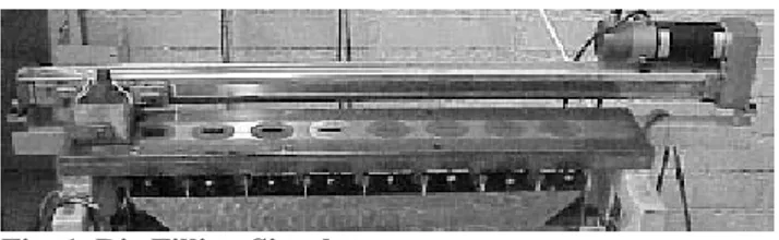
Equipment for simulation of die filling performance was used to evaluate the powders, with and without using aeration filling4. The equipment has eight cavities with
varying widths between 1 mm and 20 mm and has a fixed length and depth of 30 mm, see figure 1.
Fig. 1. Die Filling Simulator
B01-08-4 2006 POWDER METALLURGY
World Congress
Improved Consistency and Productivity by Aeration Filling Technology
and High Performance Powder Mixes
Mats Larsson1,a, Naghi Solimanjad1,b, Mikael Dahlberg1,c, Yoshinubu Takeda2,d, and Mikio Kondoh3,e 1
Höganäs AB, SE-263 83 Höganäs, Sweden
2
Höganäs Japan K.K., Akasaka Shasta East Building, 2-19, Akasaka, 4-Chome, Minato-Ku, JP Tokyo 107-0052, Japan
3
Toyota Central R&D Labs., Inc. Nagakute, Aichi 480-1192, Japan
a
[email protected], b [email protected],
c
[email protected], d [email protected], e [email protected]
Abstract
Filling of the tool die directly influences dimensional tolerances and density variation. To minimize the variations in filling, both within different sections of the cavity and from part to part, are of great importance for produce high quality P/M parts. Filling of the tool die is also one of the limiting factors in the productivity in powder pressing. By using aeration filling in combination with bonded powder mixes, both weight scatter and productivity can be improved. In this presentation results are presented showing the benefit of using aeration filling for different types of powders
© Korean Powder Metallurgy Institute 743
-The cavities were filled in sequence at different fill shoe velocities and the powder from each cavity was subsequently collected and weighed. Based on the weight of the powder and volume of the cavity, a filling density was calculated for each cavity. A filling index was defined in order to simplify interpretation of the results. Filling index was calculated according to equation 1 and was plotted versus the filling velocity.
% 100 13 2 13 − × = mm mm mm AD AD AD index Filling (1)
Results with the die filling simulation are presented in figure 2. From the results it is seen that the use of aeration filling enables higher fill shoe velocity without increased density variation. Higher filling index indicates a stronger influence on fill density from the width of the cavity.
0% 5% 10% 15% 20% 0 50 100 150 200 250 Fill speed [mm/s] F ill index Aeration Conventional
Fig. 2. Filling index versus velocity of Powder 1
To evaluate weight scatter between components under production like conditions, ring shaped parts were pressed in a Dorst TPA 45 mechanical press with gravity filling. The parts had diameters 25/19 mm and the fill depth was 32 mm. Parts were pressed at various press rates and the weight scatter was evaluated by weighing each part consecutively. 200 parts were pressed at each setting. The geometry of the part, i.e. with narrow wall section was chosen to have a difficult case that distinguishes the powders.
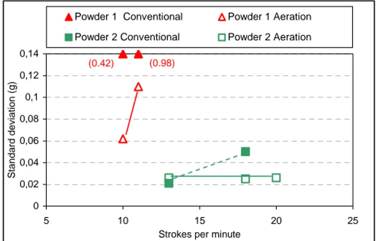
The results for weight scatter from continuous pressing are presented in figure 3. The two powders had differences in powder properties and filling characteristics. This had an impact on weight scatter as well as the maximum possible press rate before incomplete filling of the cavity resulted in significantly increased weight scatter.
Powder 1 had powder properties comparable to an elemental powder mix. By use of aeration, complete filling of the cavity of the press tool was obtained at 10 strokes per minute (the lowest possible rate of the press). Without aeration complete filling of the parts was not achieved due to the relatively difficult geometry of the thin walled ring. Powder 2 had significantly improved powder properties, which resulted in a much smaller weight scatter, with and without use of aeration at 13 strokes per minute. By using aeration filling the same low weight scatter was also
obtained at press rates of up to 20 strokes per minutes. Without use of aeration, complete filling was not obtained at 18 strokes per minutes.
0 0,02 0,04 0,06 0,08 0,1 0,12 0,14 5 10 15 20 25
Strokes per minute
S
tandard dev
iation (g)
Powder 1 Conventional Powder 1 Aeration Powder 2 Conventional Powder 2 Aeration
(0.98) (0.42)
Fig. 3. Weight scatter of pressed parts
3. Summary
It has been shown that filling of the tool die is improved by aeration of the powder in the fill shoe. By using aeration narrow sections of a tool die are filled with less decrease in fill density due to the geometry. It is also shown that higher press rates are possible without increasing the weight scatter by using aeration filling. By using a combination of aeration filling and powder with good flow behavior, weight scatter from part to part can be minimized and higher productivity can be achieved.
4. References
1. M. Kondoh, S. Takemoto, I. Urata 1998 Powder Metallurgy World Congress Proceedings Vol. 2, pp. 85-90, (1998)
2. I. Urata, S. Takemoto, M. Kondoh, 1998 Powder Metallurgy World Congress Proceedings Vol. 2, pp. 91-96, (1998)
3. U. Engström, Horizons of Powder Metallurgy. Part 1; Düsseldorf; FRG; pp. 416-424. (1986)
4. H. Vidarsson, J. Arvidsson, Proceedings of Powder Metallurgy World Congress 2000, Part 1, Kyoto, Japan; p. 413 – 416 (2000)