https://doi.org/10.1007/s42823-020-00131-3
ORIGINAL ARTICLE
Continuous synthesis of high‑crystalline carbon nanotubes
by controlling the configuration of the injection part in the floating
catalyst chemical vapor deposition process
Ji Hong Park1,2 · Junbeom Park1 · Sung‑Hyun Lee1 · Seung Min Kim1
Received: 4 November 2019 / Revised: 29 January 2020 / Accepted: 17 February 2020 / Published online: 4 March 2020 © Korean Carbon Society 2020
Abstract
Continuous synthesis of high-crystalline carbon nanotubes (CNTs) is achieved by reconfiguring the injection part in the reactor that is used in the floating catalyst chemical vapor deposition (FC-CVD) process. The degree of gas mixing is divided into three cases by adjusting the configuration of the injection part: Case 1: most-delayed gas mixing (reference experiment), Case 2: earlier gas mixing than Case 1, Case 3: earliest gas mixing. The optimal synthesis condition is obtained using design of experiment (DOE) in the design of Case 1, and then is applied to the other cases to compare the synthesis results. In all cases, the experiments are performed by varying the timing of gas mixing while keeping the synthesis conditions constant. Production rate (Case 1: 0.63 mg/min, Case 2: 0.68 mg/min, Case 3: 1.29 mg/min) and carbon content (Case 1: 39.6 wt%, Case 2: 57.1 wt%, Case 3: 71.6 wt%) increase as the gas-mixing level increases. The amount of by-products decreases step-wise as the gas-mixing level increases. The IG/ID ratio increases by a factor of 7 from 10.3 (Case 1) to 71.7 (Case 3) as the
gas-mixing level increases; a high ratio indicates high-crystalline CNTs. The radial breathing mode (RBM) peak of Raman spectrograph is the narrowest and sharpest in Case 3; this result suggests that the diameter of the synthesized CNTs is the most uniform in Case 3. This study demonstrates the importance of configuration of the injection part of the reactor for CNT synthesis using FC-CVD.
Keywords Carbon nanotube (CNT) · Synthesis · Gas mixing · Floating catalyst chemical vapor deposition
1 Introduction
Carbon nanotubes (CNTs) are useful materials in many applications due to theoretically excellent mechanical and electrical properties with light weight. However, the
application of CNTs is significantly restricted by their high price, which is a consequence of the low productivity of processes to synthesize them. Therefore, CNTs are currently used only in high-value applications. To widen the fields of applications to which CNTs are applied, the productivity of CNT synthesis must be increased.
Floating catalyst chemical vapor deposition (FC-CVD) method has the clear advantage over other synthesis meth-ods [1–6] in terms of its scalability to a mass production, because CNTs can inherently be synthesized in a continu-ous manner. Also, it is not necessary to prepare catalyst-deposited support materials or substrates. Since the catalyst particles are formed in the gas phase, CNTs can be synthe-sized at higher temperatures than other CVD-based tech-niques, which makes FC-CVD favorable to produce high-crystalline CNTs. Finally, as-synthesized CNTs by FC-CVD only includes residual catalyst particles without supporting ceramic beads which are usually used in highly efficient fluidized-bed CVD method [7], so it is easier to purify as-synthesized CNTs by FC-CVD with simple acid treatments.
Print ISSN 1976-4251
Electronic supplementary material The online version of this article (https ://doi.org/10.1007/s4282 3-020-00131 -3) contains supplementary material, which is available to authorized users. * Sung-Hyun Lee
[email protected] * Seung Min Kim [email protected]
1 Institute of Advanced Composite Materials, Korea
Institute of Science and Technology (KIST), 92
Chudong-ro, Bongdong-eup, Wanju-gun, Jeonbuk 55324, Republic of Korea
2 Department of Carbon Materials and Fiber Engineering,
Chonbuk National University, 567, Baekje-daero, Deokjin-gu, Jeonju-si, Jeonbuk 54896, Republic of Korea
Therefore, FC-CVD is a highly favorable method to synthe-size high-crystalline CNTs in a scalable way.
So far, most studies on FC-CVD synthesis of CNTs have focused on the types, compositions or overall flow rates of carbon and catalyst precursors, and carrier gases. However, all reactions during FC-CVD process including the forma-tion of catalyst particles, and the nucleaforma-tion and growth of CNTs on catalyst particles occur in the gas phase, so the way how all precursors and carrier gases are mixed is of critical significance to the crystallinity and production rates of CNTs. If mixing among various precursors is poor, even though overall compositions or concentrations of the pre-cursors are proper, the local compositions or concentrations of the precursors in the gas phase vary in the reactor, so side-reactions among precursors lead to yield large amounts of impurities and by-products instead of producing high-crystalline CNTs [6, 8]. Therefore, the effects of the gas mixing on CNT synthesis by FC-CVD must not be over-looked. Some previous studies have considered the gas mix-ing [1–5, 8–12], but very few have considered the degree of gas mixing.
In this work, we evaluate how much the degree of gas mixing with the constant composition of the precursors affects the production of CNTs. We divide the degree of gas mixing into three levels by adjusting the inlet configurations to verify the effects of gas-mixing levels. The three cases dif-fer in the timing of gas mixing and the temperature around the expected mixing point. The temperature is chosen to be lower than the thermal decomposition temperature of the precursors, so that no reaction occurs before gas mixing. We conduct synthesis optimization under mixing condi-tions that had been judged to be the worst, and observe how much difference would be seen when the mixing conditions are improved by adjustment of the inlet configurations. For synthesis optimization, design of experiments (DOE) is used [13]. This study suggests that the gas injection method and the equipment configuration must be considered during CNT synthesis using FC-CVD.
2 Experimental
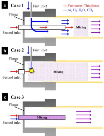
2.1 Synthesis of CNTsCNTs were continuously synthesized using FC-CVD. The main reactor (Fig. S1) consisted of a cylindrical electric fur-nace with its long axis horizontal, equipped with an alumina tube (inner diameter: 50 mm, length: 1200 mm). Three con-figurations of injection tubes were used to vary the degree of mixing of feed materials (Fig. 1).
Ferrocene (catalyst precursor) and thiophene (promoter) were evaporated in a pre-heater and blown into the reactor using Ar carrier gas; in all cases, they were administered
through an inlet in the center of one end of the furnace (the second inlet), through a tube (4-mm inner diameter). The amounts of ferrocene and thiophene were individually controlled using Ar gas at fixed temperature (ferrocene: 60 °C, thiophene: − 5 °C).
Depending on the case, methane (CH4), hydrogen (H2), argon (Ar) and H2O bubbled with Ar were introduced
using a mass flow controller (MFC), either through the first inlet that was vertically perpendicular to the first, or through the same tube.
Case 1 (two inlets; no collision, indirect mixing) (Fig. 1a): methane, hydrogen, argon and water were injected vertically downward through the first inlet. The end point of the second inlet tube (for ferrocene and thio-phene) was 11 cm from the flange of the reactor. In this case, the mixing of all reactants starts 11 cm from the inlet flange.
Case 2 (collision, direct mixing) (Fig. 1b) also uses two inlets, but the horizontal inlet tube (the second inlet tube) was reduced in length, so that its end was 0 mm from the flange. Compared to Case 1, this arrangement allows the
Fig. 1 Schematic diagram of the three inlet configurations. Case 1, No collision, indirect mixing: end of second inlet 11 cm from a flange of reactor (2 inlets). Case 2, Collision, direct mixing: end of second inlet 0 cm from a flange of reactor (2 inlets). Case 3, Well mixed: first inlet removed, end of second inlet 11 cm from a flange of reactor (1 inlet), all reactants and gases injected through one inlet
reactants coming from the two inlets to mix slightly better at the injection part of the reactor.
For Case 3 (well mixed) (Fig. 1c), all reactants were injected through the second inlet, so they were already well mixed when they entered the reactor.
Under all conditions, the concentrations of reactants and the total flow rate were constant, and the reactants did not decompose inside the inlet tube, because decom-position temperatures are ~ 400 °C (ferrocene) and 600 °C (thiophene).
2.2 Finding the optimum conditions using DOE
Five experimental variables (methane, ferrocene, thio-phene, hydrogen, water) were selected; ranges (Table S1) were chosen by reference to the literature. The results of the experiments were expressed as ratings (Table S2). DOE was performed in two stages (fractional factorial design and Box-Behnken design), using Case 1. Experimental results from the Case 1 were used as baseline references in this study. In the first stage, the major factors that have the greatest influ-ence on the experiment were identified among the many fac-tors (Table S3). In the second stage, synthesis optimization was performed by adjusting the major factors (Table S4). All these DOE methods were done using MINITAB (Minitab®
16.2.4, Minitab Inc.).
2.3 Morphology and properties’ analysis
The morphology of synthesized CNTs was observed using a transmission electron microscope (TEM, FEI Tecnai G2). The carbon content of the synthesized CNTs was measured using a thermogravimetric analyzer (TGA, Labsys Evo TG-DTA). Raman spectra of synthesized CNTs were meas-ured using a Raman spectroscope (Renishaw InVia, laser 514 nm); then the intensities IG of the G peak and ID of the D peak were compared as ratio IG/ID.
3 Results and discussion
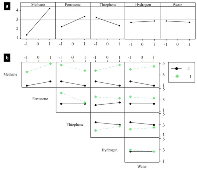
3.1 Optimization using DOETo investigate the effect of mixing between the reactants on the synthesis of CNTs in the reactor, the optimal point for synthesis condition of CNTs was obtained using DOE for Case 1, which is considered to be the worst mixing. The results of the experiment were indicated by rating-numbers (Table S2). The fractional factorial design (Fig. 2a) deter-mined that methane, ferrocene, and thiophene are more important factors for the synthesis of CNTs than are hydro-gen and water. Plots showed that interactions between the major factors greatly influenced the experimental results
(Fig. 2b). Among the major factors, methane had the great-est influence on the experimental results, and interacted sig-nificantly with other factors. To obtain high rating-numbers, the reaction must proceed at high methane and ferrocene concentrations, but low thiophene concentration. Hydrogen and water interacted with thiophene, but had small influence as main factors, so they were not adopted as major factors in the next step.
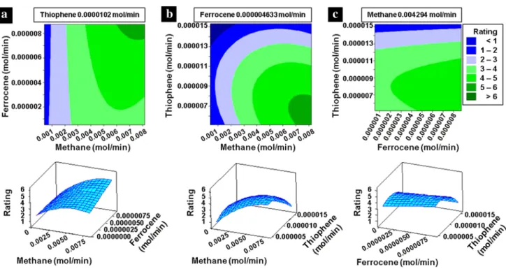
Experiments for optimization used the Box-Behnken design. Response surfaces (Fig. 3) show that the optimal point (Table 1) is far from the center of the experimental range. When thiophene is present in a large amount, it inhib-its the synthesis of CNTs [14]. Therefore, a high rating-num-ber can be obtained when the concentration of thiophene is low. Sufficient supplies of carbon source and iron catalyst are necessary, but a relatively small amount of thiophene is needed for stable synthesis of CNTs.
3.2 The effect of gas mixing by designing the injection parts
The mixing of reactants injected into the reactor has a great influence on the continuous synthesis of high-quality CNTs. Contact between iron and sulfur is important, because sulfur promotes nucleation of CNTs [14, 15]. The supply and mix-ing of methane as the carbon precursor are also important. The three cases yielded different amounts of residual carbon materials (Fig. 4). The definitions of the production rate and the carbon content used in this study are as follows:
W1: the total weight of product (mg); W2: the weight of
residual catalyst (mg); t: the synthesis time (min).
Carbon content increased in Case 3 experiment, in which the mixing of reactants was the best (Fig. 4a). This result shows that the mixing between reactants in Case 1 and Case 2 was insufficient. In Case 2, the carbon content is higher than in Case 1, because the ferrocene, thiophene had better contact with methane than in Case 1. Case 3 had the highest carbon content and nearly twice the production rate than Case 1 (related videos are attached to the electronic supple-mentary material). In Case 3, mixing had already progressed well, because all reactants were injected into one narrow inlet tube; for this reason, the carbon content and produc-tion rate are much higher than in the other two cases. As the mixing of reactants increased, the efficiency of the catalyst increased and the amount of residual material decreased (Fig. 4b).
(1) Production rate(mg∕min) = W1− W2
t (2) Carbon content(wt%) = W1− W2 W 1 × 100.
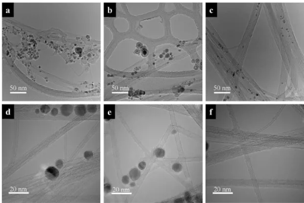
The three cases synthesized different products (Fig. 5). In Case 1, the heterogeneous mixing of ferrocene, thiophene and methane results in formation of various sizes of cata-lysts, and yields carbon materials that have low crystallinity. Therefore, this case yielded amorphous carbon products, and only small amounts of CNTs and (Fig. 5a). In Case 2, the mixing of reactants started earlier than in Case 1, so amor-phous carbon materials did not form (Fig. 5b). In addition, the CNT bundle formed from the synthesized CNTs was larger than in Case 1. The production rate of CNTs in Case 2 increased, because all reactants were mixed before Case 1. However, the sizes of the catalysts were still non-uniform, so some of them became capsulated in carbon. In Case 3, the mixing was complete, so catalyst size was fairly uniform and numerous CNTs were synthesized; the CNT bundles were also large (Fig. 5c). The absence of enlarged iron particles is consistent with the TGA result that suggests a low residual catalyst ratio (Fig. 4b). In all cases, the synthesized CNTs have a few walls (Fig. 5d–f). The CNTs synthesized from
the three experiments had similar diameters and number of walls despite the differences in the degree of mixing of the reactants. Once the catalyst particles are formed, CNT synthesis will be limited if the catalyst particles properly interact with carbon precursors. Therefore, it can be inferred that the increase in the productivity of Case 3 is not caused by the change of type or diameter of CNT, but rather by the increase of catalyst-carbon contact and thus the increase of the number density of synthesized CNTs.
Raman spectra (Fig. 6) of CNTs showed distinct differ-ences in the products of the three cases. The G peak is asso-ciated with the sp2 bond of carbon atoms, and is an indicator
of graphitization. The D peak is associated with the sp3 bond
of carbon atoms, and is an indicator of defect structure. The ratio IG/ID of the heights of the G and D peaks is an index
that strongly correlates with the quality of CNTs. The IG/ID
ratio of the synthesized CNTs increased as the mixing of reactants improved (Fig. 6a). IG/ID was 7 times higher in CNTs synthesized by Case 3 than in CNTs synthesized by
Fig 2 Analysis of fractional factorial design. a Main effects plots, b interaction plots. Methane, ferrocene, and thiophene were major variables; hydrogen and water were minor variables
Case 1. The synthesis of high-quality CNTs and the decrease of amorphous carbon materials was a result of the increased mixing of ferrocene, thiophene, methane and hydrogen. The RBM peak in the Raman spectrum is strongly correlated with the diameter of the CNTs. The RBM peaks were sig-nificantly taller and narrower for CNTs synthesized in Case 3 than in the other cases (Fig. 6b and S2). Together, these results indicate that the ratio of CNTs to by-products and
Fig. 3 Response surface plots of rating vs two independent factors: a methane flow rate and ferrocene flow rate, and b methane flow rate and thiophene flow rate, and c ferrocene flow rate and thiophene flow
rate. Within the experimental range, the optimal point was near the upper right in (a), and near the lower right in (b) and (c)
Table 1 Synthesis condition of the CNT aerogel obtained using DOE
Factors Symbols Optimum point
Methane flow rate (mol/min) X1 8.18 × 10⁻³
Ferrocene flow rate (mol/min) X2 8.74 × 10⁻⁶
Thiophene flow rate (mol/min) X3 5.61 × 10⁻⁶
Hydrogen flow rate (mol/min) X4 4.75 × 10⁻²
Water flow rate (mol/min) X5 9.90 × 10⁻⁵
Fig. 4 a Production rate, carbon content and b thermogravimetric analysis of each case. The carbon content increased as gas mixing improved; the production rate of Case 3 was ~ 1.8 times higher than the other cases
the uniformity of CNTs were both higher in Case 3 than in the others. The IG/ID ratio of the CNTs synthesized in Case 3 is among the highest compared to the IG/ID ratios of CNTs
reported in the references [2, 3, 10–12, 14, 16–20] (Fig. 7), indicating that the CNTs synthesized in Case 3 have high crystallinity.
4 Conclusion
We synthesized CNTs with high production rate and high quality by controlling the injection method of reactants during FC-CVD. The injection method was controlled by changing the configuration of the injection part of the
Fig. 5 TEM images of the CNTs and catalyst particles synthesized at each case. a, d Case 1. b, e Case 2. c, f Case 3
Fig. 6 a IG/ID ratios of CNTs
and b RBM peaks of in three cases. The IG/ID ratio increased
as gas mixing improved. CNTs synthesized in the best-mixed Case 3 show a sharper peak CNTs synthesized by Case 1 and 2
Fig. 7 Comparison of IG/ID ratios of CNTs reported in the literatures with that of CNTs synthesized in this work
reactor, and the synthesis conditions were obtained by DOE. Methane, ferrocene and thiophene had stronger influence than hydrogen and water on CNT synthesis results. The experiments were performed with three configurations of the inlet to change the mixing degree of these factors. When precursors associated with catalyst formation (ferrocene and thiophene) and carbon precursor (methane) were injected using different inlets into the reactor, the carbon content of the product decreased and impurities increased. When ferro-cene, thiophene and methane were injected through a single inlet, the mixture of reactants was the most thorough, and the synthesis yielded CNTs with high production rate, high car-bon content and low residual material; this result occurred, because many active catalysts formed from the homogene-ous mixture of reactants, so a large amount of CNTs with high IG/ID ratio were formed. These results emphasize the importance of the configuration of CVD reactor and will greatly contribute the industrialization of highly crystalline CNTs.
Acknowledgements This study was supported by the grants from the Korea Institute of Science and Technology (KIST) Open Research Pro-gram, the Industrial Fundamental Technology Development Program (10052838, development of the direct spinning process for continuous carbon nanotube fiber) funded by the Ministry of Trade, Industry and Energy (MOTIE).
References
1. Rabbani FA, Malaibari ZO, Atieh MA, Jamie A (2016) Catalytic synthesis of substrate-free, aligned and tailored high aspect ratio multiwall carbon nanotubes in an ultrasonic atomization head CVD reactor. J Nanomater 81:1
2. Simate GS, Moothi K, Meyyappan M, Iyuke SE, Ndlovu S, Fal-con R, Heydenrych M (2014) Kinetic model of carbon nanotube production from carbon dioxide in a floating catalytic chemical vapour deposition reactor. RSC Adv 4(19):9564
3. Aberefa O, Bedasie K, Madhi S, Daramola MO, Iyuke SE (2018) Production of carbon nanotube yarn from swirled floating catalyst chemical vapour deposition: a preliminary study. Adv Nat Sci Nanosci Nanotechnol 9(3):35009
4. Abdulkareem AS, Afolabi AS, Iyuke SE, Vz Pienaar HC (2007) Synthesis of carbon nanotubes by swirled floating catalyst chemi-cal vapour deposition method. J Nanosci Nanotechnol 7(9):3233 5. Barnard JS, Paukner C, Koziol KK (2016) The role of carbon
precursor on carbon nanotube chirality in floating catalyst chemi-cal vapour deposition. Nanoschemi-cale 8(39):17262
6. Mhlanga SD, Mondal KC, Naidoo N, Kunjuzwa N, Witcomb MJ, Coville NJ (2009) Synthesis and study of carbon microspheres for use as catalyst support for cobalt. South Afr J Sci 105(7–8):304
7. Zhang Q, Zhao MQ, Huang JQ, Nie JQ, Wei F (2010) Mass pro-duction of aligned carbon nanotube arrays by fluidized bed cata-lytic chemical vapor deposition. Carbon 48(4):1196
8. Hoecker C, Smail F, Bajada M, Pick M, Boies A (2016) Cata-lyst nanoparticle growth dynamics and their influence on product morphology in a CVD process for continuous carbon nanotube synthesis. Carbon 96:116
9. Lee SH, Kim HR, Lee T, Lee H, Lee J, Lee J, Lee KH et al (2017) Synthesis of carbon nanotube fibers from carbon precursors with low decomposition temperatures using a direct spinning process. Carbon 124:219
10. Bronikowski MJ, Willis PA, Colbert DT, Smith KA, Smalley RE (2001) Gas-phase production of carbon single-walled nanotubes from carbon monoxide via the HiPco process: a parametric study. J Vac Sci Technol A Vac Surf Films 19(4):1800
11. Afolabi AS, Abdulkareem AS, Iyuke SE (2007) Synthesis of car-bon nanotubes and nanoballs by swirled floating catalyst chemical vapour deposition method. J Exp Nanosci 2(4):269
12. Hoecker C, Smail F, Pick M, Boies A (2017) The influence of carbon source and catalyst nanoparticles on CVD synthesis of CNT aerogel. Chem Eng J 314:388
13. Lee SH, Park J, Kim HR, Lee T, Lee J, Im YO, Lee KH et al (2016) Synthesis of carbon nanotube fibers using the direct spin-ning process based on design of experiment (DOE). Carbon 100:647
14. Paukner C, Koziol KK (2014) Ultra-pure single wall carbon nano-tube fibres continuously spun without promoter. Sci Rep 4:3903 15. Hoecker C, Smail F, Pick M, Weller L, Boies AM (2017) The
dependence of CNT aerogel synthesis on sulfur-driven catalyst nucleation processes and a critical catalyst particle mass concen-tration. Sci Rep 7(1):14519
16. Lee SH, Park J, Kim HR, Lee J, Lee KH et al (2015) Synthesis of high-quality carbon nanotube fibers by controlling the effects of sulfur on the catalyst agglomeration during the direct spinning process. RSC Adv 5(52):41894
17. Lamura G, Andreone A, Yang Y, Barbara P, Vigolo B, Hérold C, Passacantando M (2007) High-crystalline single-and double-walled carbon nanotube mats grown by chemical vapor deposition. J Phys Chem C 111(42):15154
18. Kashi MB, Aghababazadeh R, Arabi H, Mirhabibi A (2016) Syn-thesis of high-quality single-and double-walled carbon nanotubes on Fe/MgO catalysts. Nanomater Nanotechnol 6:38
19. Moon SY, Kim WS, Kim CS (2018) Structure transformation by sp2 hydrocarbon assisted carbon nanotube growth. RSC Adv 8(45):25815
20. Yardimci AI, Yılmaz S, Selamet Y (2015) The effects of cata-lyst pretreatment, growth atmosphere and temperature on carbon nanotube synthesis using Co–Mo/MgO catalyst. Diamond Relat Mater 60:81
Publisher’s Note Springer Nature remains neutral with regard to jurisdictional claims in published maps and institutional affiliations.