MCP/CEDM Power Controller for Integral Reactor
Joon-Koo Lee, Yong-Sung Park*, Ki-Ho Cho*, Chang-Hwan Cho*, Kui –Suk Chang, Sang-Moon Seo, Heui-Youn Park, In-Soo Koo
Man Machine Interface System Development Department, Korea Atomic Energy Research Institute Samchang Enterprise Co Ltd.*
P.O BOX 105, Yuseong, Daejeon, 305-353, Korea 1. Introduction
MMIS(Man Machine Interface System) of an integral reactor is composed of a Control Room, Plant Protection System, Control System and Monitoring System which are related with the overall plant operation.
MMIS is being developed with a new design concept and digital technology to reduce the Human Factor Error and improve the systems’ safety, reliability and availability. And CCS(component control system) is also being developed with a new design concept and digital hardware technology
A fully digitalized system and design concept are introduced in the NSSS CCS.
2. MCP/CEDM Power Controller 2.1 MCP Control System
There are four(4) MCPs vertically installed on the top annular cover of the RPV(Reactor Pressure Vessel). Each MCP is an integral unit consisting of a canned asynchronous three phase motor and an axial-flow single-stage pump. CCS for MCP regulates the MCP speed with a 1100/1800/3600 rpm velocity and a 30rpm/sec variation limitation.
2.1.1 Configuration
MCPCS is fully digitalized and independently operated regardless of the individual CCS failures. MCPCS is composed of a microprocessor board, photo coupler, switch driver, SMPS and so on. MCPCS configuration is shown in figure 1.
2.1.2 SMPS(Switched Mode Power Supply)
SMPS is the power conversion equipment for modulating the frequency of the AC power source. SMPS is composed of a 3 phase rectifier, switching device (such as IGBT, MOSFET), photo coupler, switching drivers and a snubber circuit. SMPS shall accommodate the maximum 480V, 100A capacity.
2.1.3 Function
MCP Controller enables MCP operate for 30RPM/sec. variation. When off site power fails. MCP Controller was designed to accommodate following speeds.
1) 1100 RPM 2) 1800 RPM 3) 3600 RPM
2.2 CEDM Control System
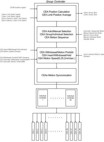
Control Element Drive Mechanism Control System(CEDMCS) receives CEA insertion, withdrawal, motion speed demand signals from the RRS, Pre-scram CS and CEDMCS can control forty nine (49) CEAs for the purpose of regulating a reactivity. Each CEDM is an integral unit consisting of a step motor and a mechanical CEDM set. CEDMCS controls the CEA motion speed with a 0.25mm/sec. or 2mm/sec. velocity and it also regulates the magnetic force in order to pull or drop the CEAs.
RRS sends the signal for the motion speed and direction to the CEDMCS sequentially.
2.2.1 Configuration
CEDM control system consists of a microprocessor board, photo coupler, switch driver and a SMPS. Figure 2 shows the simplified block diagram of the CEDMCS.
2.2.2 SMPS(Switch Mode Power Supply)
SMPS is the power conversion equipment for modulating the frequency of the AC power source. Main Function of the SMPS is to provide a modulated/varied 4 phase pulse voltage source for the step motors which move CEAs up or down. There are a total forty nine (49) CEDM SMPSs which receive CEA motion demand signals from the CEDM group controller.
SMPS is composed of a 3 phase rectifier, switching device (such as IGBT, MOSFET), photo coupler and switching drivers and a snubber circuit. SMPS accommodates the maximum 120V, 5A capacity.
Transactions of the Korean Nuclear Society Autumn Meeting Busan, Korea, October 27-28, 2005
2.2.3 Function
Step motor moves with 2mm/sec. or 0.25mm/sec. Function of controller is to provide a modulated/varied voltage source for step motor which move CEAs up or down.
Controller was designed to accommodate following function.
1) Step Motor Pulse read & store 2) Holding Current Check 3) Mechanical Action Check
3. Conclusion
NSSS CCS was developed with a new design concept and digital technology to reduce the Human Factor Error. NSSS CCS was introduced with an individual controller and group controller in integral reactor in order to increase the system reliability and availability.
NSSS CCS system was composed of microprocessor board, SMPS and so on. Overall CCS is operated normally in spite of the local system failures. The characteristics of CCS in an integral reactor have high redundancy and availability because of the introduction of the individual/group controller.
Individual Controller 1
CEA Position Calculation CEA Limit Position Average
CEA Auto/Manual Selection CEA Group/Individual Selection
CEA Motion Sequence
CEAs Motion Syncronization
Automatic Sequential Mode Manual Sequential Mode Manual Group Mode Manual Individual Mode Standby Mode CEDM position signal
Upper Limit Switch signal Lower Limit Switch signal Quick Insertion Upper Limit Switch Quick Insertion Loser Limit Switch
Upper Group Stop Lower Group Stop
Individual Controller 49 CEA 1 CEA 2 CEA 3 CEA 4 CEA 4 6 CEA 4 7 CEA 4 8 CEA 4 9 Group Controller
CEA Withdrawal/Motion Prohibit CEA Insert/Withdrawal/Hold CEA Motion Speed(0.25,2mm/sec.)
CEA Insert/Withdrawal/Hold demand CEA Motion Speed Demand CEA Withdrawal Prohibit(CWP) Demand CEA Automatic Withdrawal Prohibit(AWP) CEA Automatic Motion Inhibit(AMI)
Quick Insertion/Motion Speed Demand
Figure 1. Simplified Functional Block Diagram of CEDMCS.
C 3P 120V S1 S2 S3 S4 S 6 S5 St e p p in g Mo to r Mi c ro P ro c esso r Re q u ir e d CEA Mov e m e nt s ig na l S7 S8 Ti m ing o r sync ro ni zat io n s ig n a l Ph ot o Co upl e r S1 S2 S3 S4 S5 S6 Sw it ch Dr iv e r S8 S7
Figure 2. Simplified CEDM Power Controller
REFERENCES
[1] M. H. Jang, G. W. Yeo, Basic Design Report of SMART, KAERI/TR-2142/2002, p. 507-527, 2002. [2] I. S. Koo, H. Y. Park, Development of MMIS Design Technology for Integral Reactor, KAERI/TR-1901/98, p.51-79, 1998.
[3] H. Hur, J.I.Kim, Basic Design Report of Main Coolant Pump for SMART, KAERI/TR-2135, 2002