Research Article
An ID/Locator Separation Based Group Mobility
Management in Wireless Body Area Network
Moneeb Gohar,
1Jin-Ghoo Choi,
1and Seok-Joo Koh
21Department of Information and Communication Engineering, Yeungnam University, Gyeongsan 712-749, Republic of Korea
2School of Computer Science and Engineering, Kyungpook National University, Daegu 702-701, Republic of Korea
Correspondence should be addressed to Jin-Ghoo Choi; [email protected] Received 14 November 2014; Accepted 20 February 2015
Academic Editor: Bo-Wei Chen
Copyright © 2015 Moneeb Gohar et al. This is an open access article distributed under the Creative Commons Attribution License, which permits unrestricted use, distribution, and reproduction in any medium, provided the original work is properly cited. Mobility management in wireless sensor network is the most important factor to be considered for applications such as healthcare system. Recently, Identifier (ID)/Locator (LOC) separation based mobility management scheme has been proposed for wireless sensor network. However, it does not perform well in group-based mobility management in wireless body area network, and thus it tends to induce large registration, packet delivery, and handover delays. To overcome these limitations, we propose a group-based mobility management scheme based on ID/LOC separation concept for ID-based communications with location-based routing to reduce the number of control messages. In the proposed scheme, each sensor device has a globally unique device identifier (GDID) which contains the information of its home network domain. For handover support, each access gateway maintains its home GDID register (HGR) and visiting GDID register (VGR) which are used to keep the GDID-locator (LOC) mappings for primary mobile devices in the distributed manner. Besides, in the proposed scheme, only the coordinator will send Router Solicitation and Router Advertisement messages to reduce the control messages further. By numerical analysis, we show that the proposed scheme can significantly reduce the registration, packet delivery, and handover delays, compared to the existing schemes.
1. Introduction
Wireless body area networks (WBANs) are emerging as an important part of the daily life for ambient assistive living. A WBAN typically consists of lightweight, low power sensors that operate in the proximity of the human body. These sensors can be attached to human body or clothes [1– 3] and can be used to measure the parameters associated with human body, typically observing physiological signals emanating from different body organs, body motions, and the surrounding environment. The measured values can be gathered and transmitted to the main server by using the IPv6 over low power wireless personal area network (6LoWPAN) [4,5], in which it is possible to connect wireless sensor nodes to IPv6 networks. In mobile environments, it is required to provide these sensor nodes with mobility management, such as handover control.
Many IPv6-based mobility management protocols have attracted much interest in 6LoWPAN networks. We can classify the protocols into the host-based schemes and
the network-based schemes. For example, Mobile IPv6 (MIPv6) is a host-based protocol [6] and Proxy Mobile IPv6 (PMIPv6) is a network-based protocol [7]. In host-based mobility schemes, the sensor exchanges Binding Update
(BU) and Binding Acknowledgment (BA) messages with its
Home Agent (HA), when it moves from one mobility domain to another. On the other hand, in network-based mobility schemes, when a sensor changes the domain, the protocols do not require any mobility-related signaling. Instead, a mobile access gateway (MAG) is responsible for detecting movement and exchanging signaling messages on behalf of the sensors. It is noted that PMIPv6 can be considered as the most suitable mobility scheme in 6LoWPAN-WBAN. However, the conventional PMIPv6 [7] scheme has a drawback that a lot of Proxy Binding Update (PBU) and Proxy Binding Ack (PBA) messages should be exchanged between LMA and MAGs for all body sensors. To enhance this conventional PMIP scheme, the PMIP-Group [8] was proposed, in which a single
De-Registration (DeReg) message is exchanged between MAG
and LMA by aggregating the associated messages from all
sensors. The PMIP-Coordinator scheme [9] was proposed for further enhancement of group-based mobility support in 6LoWPAN-based WBAN network. In this scheme, the
Coor-dinator will communicate with MAG on behalf of the body
sensor. The PMIP-Coordinator still has large registration and handover delay.
The Identifier (ID)/Locator (LOC) based mobility man-agement scheme has been proposed for 6LoWPAN wireless sensor network [10]. In this scheme each primary mobile device (PMD) or 6LoWPAN sensor has a 128-bit global unique device identifier (GDID), which is used for end-to-end communication, and a link-layer address can be used as the access identifier (AID). Each local network domain will have a local home mobility agent and a local visited mobility agent, which are configured based on the logical overlay network that supports the distributed mapping management. However, this scheme does not perform well in group-based wireless body area network, because each sensor sends Router
Solicitation (RS) and Router Advertisement (RA) messages
to PMD. In addition, for location update and discovery, the additional control messages are exchanged between access gateway and distributed local mapping agents. This tends to induce large registration and handover delays. For this reason, how to decrease the times of exchanging the control messages in case that a number of sensors are attached on one PMD is an important issue.
To overcome these limitations, we propose a group-based mobility management scheme group-based on the ID/LOC separation concept. In the proposed scheme, each sensor and each primary mobile device has a globally unique device identifier (GDID) which contains the information of home network domain. For handover support, each access gateway maintains “home GDID register” and “visiting GDID regis-ter” that are used to keep the GDID-global locator (GLOC) mappings for primary mobile devices in the distributed manner. The proposed scheme also reduces the number of control messages, including RS/RA. This is because only the Coordinator will exchange RS/RA messages with PMD, instead of each sensor.
The rest of this paper is organized as follows. InSection 2, we review the existing ID/LOC schemes for 6LoWPAN-WBAN networks. In Section 3, we describe the proposed ID/LOC scheme in detail. The performances of the existing and proposed schemes are analyzed inSection 4in terms of the registration delay, packet delivery delay, and the handover delay. We provide the numerical results and discuss them in Section 5. Finally, we conclude this research inSection 6.
2. Related Works
In conventional PMIPv6 scheme [7], a lot of Proxy Binding
Update (PBU) and Proxy Binding Ack (PBA) messages are
exchanged between LMA and MAGs for all body sensors. To enhance this conventional PMIP scheme, the PMIP-Group [8] was proposed, in which a single De-Registration (DeReg) message is exchanged between MAG and LMA for all body sensors.
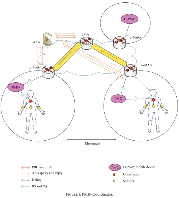
The PMIP-Coordinator scheme [9] was proposed for fur-ther enhancement of PMIP-Group scheme. In this scheme, the Coordinator will communicate with MAG on behalf of the body sensor.
As shown inFigure 1, when the Coordinator is detached from previous MAG (p-MAG), a single DeReg message is exchanged between p-MAG and LMA by aggregating the associated messages from all sensors.
When the Coordinator is attached to n-MAG, then it sends a single Router Solicitation (RS) message, which contains the associated group information, MN-IDs, and link-layer address, to n-MAG by way of PMD at a time. Upon reception of RS messages from body sensors, n-MAG will send the Authentication-Authorization-Accounting
(AAA) query messages for authentication for all body sensors.
After authentication, AAA server responds with AAA reply messages, containing the LMA address, to MAG. Then, n-MAG will send aggregated Proxy Binding Update (PBU) mes-sage to LMA for all body sensors. Now, LMA will perform the AAA query operation with AAA server by exchanging AAA
query and reply messages for each sensor. After that, LMA
sends aggregated Proxy Binding ACK (PBA) message to n-MAG in response to the respective aggregated PBU message. Then, n-MAG responds with a Router Advertisement (RA) message to the Coordinator in response to the RS message.
If PMD wants to communicate with the corresponding PMD (C-PMD), then PMD will send a data packet to LMA directly and LMA will forward the data packet to corresponding MAG (c-MAG) and further to C-PMD.
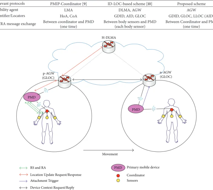
The ID/LOC-based mobility management scheme has been proposed for 6LoWPAN wireless sensor network [10]. In this paper, we will consider it for 6LoWPAN-based wireless body area network. In the ID/LOC scheme, each primary mobile device (PMD), such as smartphone or tablet PC and 6LoWPAN sensor, has a 128-bit globally unique device identifier (GDID), which is used for end-to-end communi-cation, and a link-layer addresses can be used as the access identifier (AID). Each local network domain will have the home and visited distributed local mobility management agents, which are based on the logical overlay network that supports the distributed mapping management. The device ID can be generated through cryptographical generated address (CGA).
As shown inFigure 2, when the body sensors are attached to PMD, then all body sensors generate their IDs and send
Router Solicitation (RS) messages to PMD. Upon reception of RS messages from body sensors, PMD will send the Location Update Request to access gateway (AGW). Then, the AGW
will update its GDID-global locator (GLOC) mapping table and also GDID-access identifier (AID) mapping table. After that, the AGW responds with Location Update Response message to PMD. After location update, the AGW also performs the Location Update Request and Response messages with distributed local mapping agent (DLMA) for adding GDID-GLOC mapping for global communication.
When PMD moves from the previous access gateway (p-AGW) to a new access gateway (n-(p-AGW), the PMD will send Attachment Trigger to n-AGW. After Attachment Trigger, n-AGW sends Device Context Request message to p-AGW.
n-MAG p-MAG Movement PMD LMA AAA PMD C-PMD c-MAG
PMD Primary mobile device
Coordinator
RS and RA
Sensors PBU and PBA
DeReg
AAA query and reply
Figure 1: PMIP-Coordinator.
Then, p-AGW will send the Location Update Request message to home DLMA (H-DLMA). The H-DLMA updates the information and responds with Location Update Response message to p-AGW. After receiving the Location Update
Response, the p-AGW will send Device Context Reply message
to n-AGW.
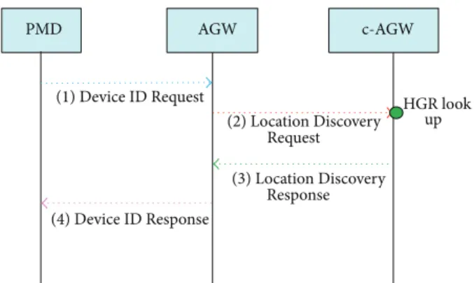
As shown inFigure 3, PMD wants to communicate with a particular PMD that is residing in the corresponding gateway (c-AGW). The PMD will send a Device ID Request message to AGW. After receiving the Device ID Request from PMD, the AGW will look up its mapping table, whether the request ID exists or not. If there is no information, then AGW sends a Location Discovery Request message to corresponding DLMA (C-DLMA). The C-DLMA will look up its mapping table and reply with a Location Discovery
Response message to AGW. Upon the receipt of the Location Discovery Response message from the CDLMA, the AGW will
add the information in its mapping table. Then, the AGW
sends Route Setup Request message to c-AGW. After that, the c-AGW performs the GDID Discovery Query and Reply messages with corresponding PMD (C-PMD). After that, the c-AGW responds with Route Setup Complete message to AGW. After that, the AGW responds with Device ID Response message to PMD. Now, the data packets will be forwarded to C-PMD via AGW and c-AGW.
3. Proposed Scheme
In this section, we describe the proposed ID/LOC-based 6LoWPAN-WBAN mobility management scheme. To this end, first we need to specify the network model.
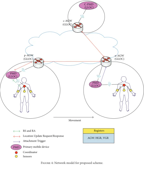
3.1. Network Model. The proposed ID/LOC-based
6LoW-PAN wireless body area network mobility management scheme is shown in Figure 4. In the model, we consider
Table 1: Comparison of mobility management architectures.
Relevant protocols PMIP-Coordinator [9] ID-LOC-based scheme [10] Proposed scheme
Mobility agent LMA DLMA, AGW AGW
Identifier/Locators HoA, CoA GDID, AID, GLOC GDID, GLOC, LLOC (AID)
RS/RA message exchange Between coordinator and PMD (one time)
Between body sensors and PMD (each body sensor)
Between Coordinator and PMD (one time) n-AGW (GLOC) p-AGW (GLOC) Movement PMD PMD H-DLMA
PMD Primary mobile device
Coordinator Sensors RS and RA
Location Update Request/Response Attachment Trigger
Device Context Request/Reply
Figure 2: ID-LOC registration and handover operations.
a group of 6LoWPAN sensors that are attached to human body, and one of them acts as Coordinator and only the
Coordinator can exchange the control signaling messages
with the primary mobile device (PMD). In the proposed scheme, each sensor or PMD has a 128-bit globally unique device identifier (GDID) [10]. The link-layer addresses can be used as the access identifier (AID). The GDID contains the information about its home network domain. As for locators, the location of PMDs is identified by local locators (LLOC) and global locators (GLOC). The local locators are the AIDs of PMDs, and it is used within the home domain. The GLOC represents the IP address of access gateways (AGW), and it is used for interdomain communication. Each AGW keeps home GDID register (HGR) and visiting GDID register (VGR). HGR keeps track of the GDID-LOC mapping information for PMDs and VGR maintain the list of GDID-LLOC mapping information for the visited PMDs.
In the proposed scheme, only one time Router Solicitation
(RS) and Router Advertisement (RA) messages are sent by Coordinator and thus reduce lots of control messages.
Initially, the PMD communicates with correspondent PMD (C-PMD) in the previous AGW (p-AGW) domain. Now, the PMD moves to a new AGW (n-AGW) by handover. In addition, we assume that each PMD moves around only within its home domain.
3.2. Comparison of Existing and Proposed Schemes. Before
describing the proposed scheme in detail, we compare the considered mobility management schemes in the architec-tural perspective inTable 1.
In the viewpoint of the mobility management, PMIP-Coordinator is the centralized architectures, in which all the control and data traffic are processed by a centralized agent such as LMA. Data packets are delivered to the centralized
c-AGW (GLOC) AGW (GLOC) C-PMD PMD C-DLMA H-DLMA
PMD Primary mobile device
Device ID Request/Response Location Discovery Request/Response GDID Discovery Query/Reply Route Setup Request/Complete
Coordinator Sensors
Figure 3: ID-LOC packet delivery operations.
agents first and forwarded to the corresponding host. In PMIP-Coordinator, the identifier corresponds to HoA and the locator does CoA. In PMIP-Coordinator, the Coordinator will exchange RS/RA messages only one time with mobile access gateway (MAG) on behalf of the body sensors.
In ID-LOC-based scheme, the GDID is used as identifier, and AID and GLOC are used for locators. The DLMA and AGW are used to manage the mobility of PMDs. In ID-LOC-based scheme, the body sensors exchange RS/RA messages with PMD.
On the other hand, in the proposed schemes, the GDID is used as identifier and LLOC and GLOC are used for locators. The AGW manages the mobility for PMDs. In the proposed scheme, the Coordinator exchanges RS/RA messages with PMD only one time on behalf of body sensors. The proposed scheme is described in the subsequent sections.
3.3. Initial Registration. The initial registration procedure of
the proposed scheme is shown inFigure 5.
In the figure, when the Coordinator is attached to PMD, the Coordinator sends a Router Solicitation (RS) message containing the information on the group, MN-IDs (GDID), and Link-Layer Addresses (AIDs) to PMD (Step 1). Upon reception of the RS message from the Coordinator, the PMD responds with RA message to Coordinator (Step 2). Then, PMD sends Location Update Request message to AGW. On the reception of this message, the AGW will update its home GDID register (HGR) which maintains GDID-LOC mapping
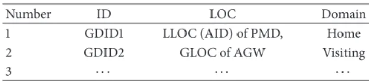
Table 2: Home GDID register (HGR).
Number ID LOC Domain
1 GDID1 LLOC (AID) of PMD, Home
2 GDID2 GLOC of AGW Visiting
3 ⋅ ⋅ ⋅ ⋅ ⋅ ⋅ ⋅ ⋅ ⋅
table as shown inTable 2. Then, AGW responds with Location
Update Response to PMD (Steps 3 and 4).
3.4. Packet Delivery Operation. InFigure 6, PMD wants to communicate with a particular PMD that is residing in the corresponding gateway (c-AGW). The PMD will send
Device ID Request message to AGW (Step 1). Next, the AGW
will check whether the GDID belongs to the same domain with the corresponding PMD or not. Note that an AGW can determine this, based on GDID, since GDID contains information about its home domain. Then, AGW sends
Location Discovery Request message to c-AGW. The c-AGW
will look up its HGR mapping table and reply with Location
Discovery Response message to AGW (Steps 2 and 3). Upon
the receipt of the Location Discovery Response message from the c-AGW, the AGW will add the information in its mapping table. After that, the AGW responds with Device ID Response message to PMD (Step 4). Now, the data packets will be forwarded to C-PMD via AGW and c-AGW.
PMD Primary mobile device RS and RA
Location Update Request/Response
n-AGW (GLOC) p-AGW (GLOC) Movement PMD PMD (LLOC) (LLOC) Attachment Trigger C-PMD (LLOC) c-AGW (GLOC) Registers AGW: HGR, VGR Coordinator Sensors
Figure 4: Network model for proposed scheme.
Coordinator PMD AGW
(1) RS (2) RA
(3) Location Update Request (4) Location Update Response
HGR update
Figure 5: Initial registration.
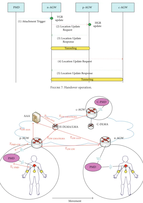
3.5. Handover Operation. When PMD moves from the
pre-vious access gateway (p-AGW) to a new access gateway (n-AGW) in the same home network domain, the PMD will send
Attachment Trigger to n-AGW (Step 1). After Attachment Trigger, the n-AGW will update its visiting GDID register
(VGR) which maintains GDID-LLOC (AID) mapping table as shown inTable 3. Then, n-AGW sends Location Update
Request message to previous AGW (p-AGW). The p-AGW
will update its HGR and responds with Location Update
Response message to n-AGW (Steps 2 and 3). The Location Update Response message shall include the information of
corresponding-AGW (c-AGW) address, which is recorded in the mapping table of p-AGW.
Now, n-AGW sends a Location Update Request message to c-AGW for route optimization. On the reception of the
Location Update Request message, c-AGW will update its
mapping table and send a Location Update Response to n-AGW. n-AGW and c-AGW will now use the optimized route (Steps 4 and 5).
c-AGW PMD AGW (1) Device ID Request (4) Device ID Response HGR look up (2) Location Discovery Request (3) Location Discovery Response
Figure 6: Packet delivery operation.
Table 3: Visiting GDID register (VGR).
Number ID LLOC
(in the visited domain) Home domain 1 GDID1 LLOC1 (AID) of PMD (AGW of GDID1)GLOC1
2 GDID2 LLOC2 (AID) of PMD GLOC2
(AGW of GDID2)
3 ⋅ ⋅ ⋅ ⋅ ⋅ ⋅ ⋅ ⋅ ⋅
4. Performance Analysis
In this section, we analyze the performances of candi-ate mobility management schemes: PMIP-Coordinator, ID-LOC-based scheme, and proposed scheme. As performance metrics, we consider the delays associated with registration, packet delivery, and handover delay, since such delays are very impormant in mobility management.
4.1. Analysis Model. We define several notations for analysis
and summarize them in the Notations section. We illustrate the considered network model inFigure 8.
InFigure 8, we denote by𝑇𝑥−𝑦(𝑆) the transmission delay of a message with size𝑆 from node 𝑥 to node 𝑦 via a wireless link. It can be expressed as𝑇𝑥−𝑦(𝑆) = ((1 − 𝑞)/(1 + 𝑞)) ⋅ ((𝑆/𝐵𝑤𝑙) + 𝐿𝑤𝑙). In the meantime, we denote by 𝑇𝑥−𝑦(𝑆, 𝐻𝑥−𝑦)
the transmission delay of a message with size𝑆 from node 𝑥 to node𝑦 via a wired link, where 𝐻𝑥−𝑦represents the number of wired hops between node 𝑥 to node 𝑦. Note that it is expressed as𝑇𝑥−𝑦(𝑆, 𝐻𝑥−𝑦) = 𝐻𝑥−𝑦⋅ ((𝑆/𝐵𝑤) + 𝐿𝑤+ 𝑇𝑞).
4.2. Analysis of Registration Delay (RD)
4.2.1. PMIP-Coordinator. As shown inFigure 1, when
Coor-dinator is attached to MAG, then it sends RS message to MAG
by way PMD. After that, the MAG performs
Authentication-Authorization-Accounting (AAA) query and reply operation
with AAA server for authentication for all body sensors. Then, the MAG performs the AAA query operation with AAA server, and then MAG performs aggregated PBU operation with LMA. Then, LMA performs the AAA query and reply operations with AAA server for each body sensor.
After authentication, LMA respond with aggregated PBA to MAG. Now, the MAG responds with aggregated RA message to Coordinator. Accordingly, we get the RD of PMIP-Coordinator as follows: RDPMIP-Coordinator = 2𝑇C-PMD(𝑆𝑐) + 2𝑇PMD-GW(𝑆𝑐) + 2𝑇GW-LMA/DLMA(𝑆𝑐) + 𝑁𝑆× {2𝑇GW-AAA(𝑆𝑐) + 2𝑇LMA-AAA(𝑆𝑐)} . (1)
4.2.2. ID-LOC-Based Scheme. As shown inFigure 2, when body sensors are attached to PMD, then it performs RS and
RA messages to PMD by way of Coordinator. After that,
the PMD performs Location Update Request and Response operation with AGW. Then, the AGW also performs the
Location Update Request and Response operation with
H-DLMA. Accordingly, we get the RD of ID-LOC-based scheme as follows:
RDID-LOC = 𝑁𝑆× {2𝑇C-PMD(𝑆𝑐)}
+ 2𝑇PMD-GW(𝑆𝑐) + 2𝑇GW-LMA/DLMA(𝑆𝑐) .
(2)
4.2.3. Proposed Scheme. As shown inFigure 5, when
Coor-dinator is attached to PMD, then it performs aggregated RS
and RA messages to PMD. After that, the PMD performs
Location Update Request and Response operation with AGW.
Accordingly, we get the RD of proposed scheme as follows: RDProposed scheme= 2𝑇C-PMD(𝑆𝑐) + 2𝑇PMD-GW(𝑆𝑐) . (3)
4.3. Analysis of Packet Delivery Delay (PDD)
4.3.1. PMIP-Coordinator. When PMD wants to
communi-cate with particular C-PMD, PMD will forward the data packets to LMA and the LMA will forward the data packet to c-AGW and further to C-PMD. Accordingly, we get the PDD of PMIP-Coordinator as follows:
PDDPMIP-Coordinator
= 2𝑇PMD-GW(𝑆𝑑) + 2𝑇GW-LMA/DLMA(𝑆𝑑) .
4.3.2. ID-LOC-Based Scheme. When PMD wants to
commu-nicate with particular C-PMD, PMD will send Device ID
Request message to AGW. If there is no information, then
AGW performs Location Discovery Request and Response message with C-DLMA. Then, AGW sends Route Setup
Request message to c-AGW. After that, the c-AGW performs
the GDID Discovery Query and Reply messages with corre-sponding PMD (C-PMD). After that, the c-AGW responds with Route Setup Complete message to AGW. After that, the AGW responds with Device ID Response message to PMD. Now, the data packets will be forwarded to C-PMD via AGW and c-AGW:
PDDID-LOC= 4𝑇PMD-GW(𝑆𝑐) + 2𝑇GW-LMA/DLMA(𝑆𝑐)
+ 2𝑇GW-GW(𝑆𝑐) + 2𝑇PMD-GW(𝑆𝑑)
+ 𝑇GW-GW(𝑆𝑑) .
(5)
4.3.3. Proposed Scheme. When PMD wants to communicate
with particular C-PMD, PMD will send Device ID Request message to AGW. If there is no information, then AGW performs Location Discovery Request and Response message with c-AGW. After that, the AGW responds with Device ID
Response message to PMD. Now, the data packets will be
forward to C-PMD via AGW and c-AGW:
PDDProposed Scheme= 2𝑇PMD-GW(𝑆𝑐) + 2𝑇GW-GW(𝑆𝑐)
+ 2𝑇PMD-GW(𝑆𝑑) + 𝑇GW-GW(𝑆𝑑) .
(6)
4.4. Analysis of Handover Delay (HD)
4.4.1. PMIP-Coordinator. As shown in Figure 1, when the
Coordinator is detached from p-MAG, then p-MAG will
send aggregated DeReg message to LMA. When Coordinator is attached to MAG, then it sends RS message to n-MAG by way PMD. After that, the n-n-MAG performs AAA
query and reply operation with AAA server for
authenti-cation for all body sensors. Then, the n-MAG performs the AAA query operation with AAA server, and then n-MAG performs aggregated PBU operation with LMA. Then, LMA performs the AAA query and reply operations with AAA server for each body sensor. After authentication, LMA responds with aggregated PBA to n-MAG. The handover tunnel is established between n-MAG and LMA. After tunnel establishment, the n-MAG responds with aggregated RA message to Coordinator. Accordingly, we get the HD of PMIP-Coordinator as follows: HDPMIP-Coordinator = 2𝑇C-PMD(𝑆𝑐) + 2𝑇PMD-GW(𝑆𝑐) + 4𝑇GW-LMA/DLMA(𝑆𝑐) + 𝑁𝑆× {2𝑇GW-AAA(𝑆𝑐) + 2𝑇LMA-AAA(𝑆𝑐)} + 𝑇GW-LMA/DLMA(𝑆𝑑) . (7)
4.4.2. ID-LOC-Based Scheme. As shown inFigure 2, when PMD is attached with n-AGW, then PMD will send
Attach-ment Trigger to n-AGW. After that, the n-AGW
per-forms Device Context Request and Reply messages with p-AGW. Then, p-AGW performs Location Update Request and
Response messages with H-DLMA. Accordingly, we get the
HD of ID-LOC-based scheme as follows: HDID-LOC = 𝑇PMD-GW(𝑆𝑐) + 2𝑇GW-GW(𝑆𝑐)
+ 2𝑇GW-LMA/DLMA(𝑆𝑐) + 𝑇GW-GW(𝑆𝑑) .
(8)
4.4.3. Proposed Scheme. As shown inFigure 7, when PMD is attached with n-AGW, then PMD will send Attachment
Trigger to n-AGW. After that, the n-AGW performs Location Update Request and Response messages with p-AGW.
Accord-ingly, we get the HD of proposed scheme as follows: HDProposed Scheme
= 𝑇PMD-GW(𝑆𝑐) + 2𝑇GW-GW(𝑆𝑐) + 𝑇GW-GW(𝑆𝑑) .
(9)
5. Numerical Results and Discussion
Based on the analytical equations given in Section 4, we compare the performances of the considered mobility man-agement schemes. In the numerical results, the default value of each parameter has been configured as follows, referring to [11]; that is,𝐻DLMS-DLMS= 5, 𝐻GW-LMA/DLMS = 5, 𝐻GW-GW =
5, 𝐻GW-AAA = 5, and 𝐻LMA-AAA = 5, and 𝐿𝑤𝑙 = 10 (ms),
𝐿𝑤 = 2 (ms), 𝑞 = 0.5, 𝑁𝑆 = 10, 𝑇𝑞 = 5 (ms), 𝑆𝑐 = 96(bytes), 𝑆𝑑 = 200 (bytes), 𝐵𝑤𝑙 = 11 (Mbps), and 𝐵𝑤 = 100 (Mbps), where 𝑁𝑆 denotes the number of sensors in the network. Among the various parameters, we note that𝐿𝑤𝑙,𝑇𝑞,𝑁𝑆, and 𝐻GW-LMA/DLMAcan depend on the network conditions. Thus,
we evaluate the performances of the considered schemes by varying the values of these parameters.
5.1. Registration Delay. We show the impact of the delay of
wireless links (𝐿𝑤𝑙) on the registration delay inFigure 9. We can see that the registration delay increases linearly as𝐿𝑤𝑙 becomes larger in every considered scheme. In particular, the PMIP-Coordinator mobility scheme is more sensitive to the delay of wireless links than the ID-LOC mobility scheme, since they exchange the signaling messages for the registration over wireless links and also perform AAA query operation with AAA server for each body sensor. The PMIP-Coordinator also performs PBU/PBA operation with LMA for binding. While ID-LOC mobility scheme performs better than PMIP-Coordinator, this is because there is no AAA query operation with AAA server, since it performs RS/RA messages with PMD for each body sensors over wireless link. We observe that the proposed scheme performs best among the candidate schemes. This is because the Coordinator performs RS/RA messages with PMD and also there is no binding operation with DLMA, since the binding operation performs with AGW.
Figure 10 compares the registration delays of candidate schemes by varying the average queuing delay (𝑇𝑞) at each
p-AGW PMD n-AGW (1) Attachment Trigger HGR update (2) Location Update Request (3) Location Update Response VGR update Tunneling c-AGW
(4) Location Update Request
(5) Location Update Response Tunneling
Figure 7: Handover operation.
n-AGW p-AGW Movement PMD AAA PMD c-AGW C-PMD H-DLMA/LMA C-DLMA TC-PMD TPMD-GW TGW-AAA TLMA -AAA TGW-AAA TGW-GW TGW-LMA/DLMA TGW-LMA/DLMA
Figure 8: Network model for performance analysis.
node. For the two schemes, PMIP-Coordinator and ID-LOC-based scheme, the registration delay increases linearly as𝑇𝑞 increase because the two schemes exchange the signaling messages with AAA, LMA, and DLMA over the wired network. In contrast, proposed scheme is not affected by the average queuing delay at all since it exchanges the signaling messages for the registration over wireless links only. We can
see that the proposed scheme performs well compared to the existing schemes.
We next illustrate the registration delay for different num-ber of sensors in the network (𝑁𝑆) inFigure 11. We observe that the PMIP-Coordinator gives worse performances than the ID-LOC-based scheme. This is because of the signaling messages for authentication with AAA server by GW and
1 3 6 10 15 21 28 36 45 55 0 200 400 600 800 1000 1200 1400 1600 1800 2000 Registra tio n dela y (m s) PMIP-Coordinator ID-LOC Proposed scheme Lwl(ms)
Figure 9: Impact of𝐿𝑤𝑙on the registration delay.
1 2 3 4 5 6 7 8 9 10 0 500 1000 1500 2000 2500 3000 Registra tio n dela y (m s) Tq(ms) PMIP-Coordinator ID-LOC Proposed scheme
Figure 10: Impact of𝑇𝑞on the registration delay.
LMA for each body sensor. In contrast, the proposed scheme is not affected by the number of sensors. This is because only
Coordinator can exchange the RS/RA messages with PMD on
behalf of body sensors.
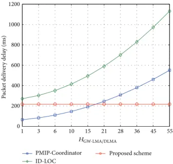
5.2. Packet Delivery Delay. We illustrate the packet delivery
delay for different hop counts between GW and LMA/DLMA (𝐻GW-LMA/DLMA) inFigure 12. We can see that𝐻GW-LMA/DLMA
affects the performances of the existing mobility schemes sig-nificantly. We observe that ID-LOC-based scheme performs poorly compared to the PMIP-Coordinator scheme. This is because there is query operation before data delivery, while PMIP-Coordinator relies on LMA in the distance for the registration and the data delivery. We can see in the figure
10 20 30 50 100 130 150 180 200 250 Registra tio n dela y (m s) PMIP-Coordinator ID-LOC Proposed scheme 4 3.5 3 2.5 2 1.5 1 0.5 0 Ns ×104
Figure 11: Impact of𝑁𝑆on the registration delay.
1 3 6 10 15 21 28 36 45 55 0 200 400 600 800 1000 1200 P ac k et deli ve ry dela y (m s) PMIP-Coordinator ID-LOC Proposed scheme HGW-LMA/DLMA
Figure 12: Impact of𝐻GW-LMA/DLMAon the packet delivery delay.
that the proposed scheme is not affected with𝐻GW-LMA/DLMA,
since AGW maintains HGR and VGR.
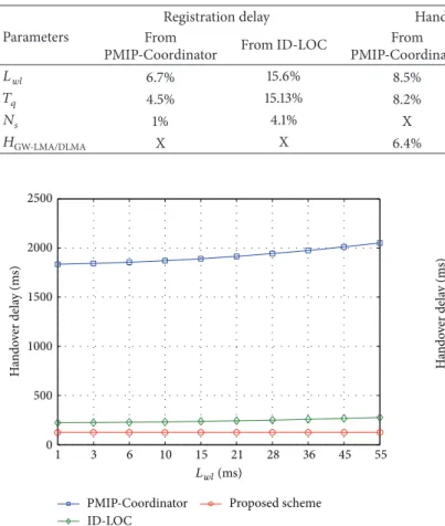
5.3. Handover Delay. The delay of wireless links (𝐿𝑤𝑙) gives a significant impact on the handover delay for the three candi-date schemes, as shown inFigure 13. In particular, the PMIP-Coordinator mobility scheme is more sensitive to the delay of wireless links than the ID-LOC mobility scheme, since the signaling messages exchanged over the wireless links spends much time in configuring a new care-of-address through the duplicate address detection procedure by handover. The PMIP-Coordinator also performs PBU/PBA operation with
Table 4: Improvement of proposed scheme from existing schemes in average percentage.
Parameters
Registration delay Handover delay Packet delivery delay
From
PMIP-Coordinator From ID-LOC
From
PMIP-Coordinator From ID-LOC
From
PMIP-Coordinator From ID-LOC
𝐿𝑤𝑙 6.7% 15.6% 8.5% 67.2% X X 𝑇𝑞 4.5% 15.13% 8.2% 66% X X 𝑁𝑠 1% 4.1% X X X X 𝐻GW-LMA/DLMA X X 6.4% 42.6% 136.1% 44.7% 1 3 6 10 15 21 28 36 45 55 0 500 1000 1500 2000 2500 H ando ver dela y (m s) PMIP-Coordinator ID-LOC Proposed scheme Lwl(ms)
Figure 13: Impact of𝐿𝑤𝑙on the handover delay.
LMA for binding. While ID-LOC mobility scheme performs better than PMIP-Coordinator, this is because there is no AAA query operation with AAA server, since it performs
RS/RA messages with PMD for each body sensor over
wireless link. We can see in the figure that proposed scheme performs best among the candidate schemes.
Figure 14shows the impact of the average queuing delay (𝑇𝑞) on the handover delay. The delay rises up linearly as 𝑇𝑞 increases in all the schemes. We observe that the PMIP-Coordinator performs worst while consuming much time in the duplicate address detection procedure.
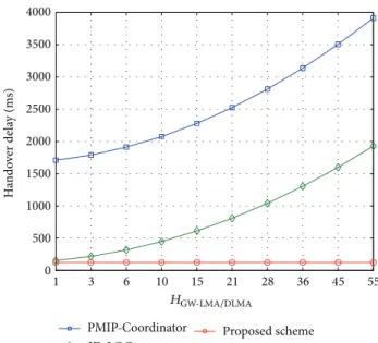
We illustrate the handover delay for different hop counts between GW and LMA/DLMA (𝐻GW-LMA/DLMA) inFigure 15.
We can see that𝐻GW-LMA/DLMA affects the performances of the existing mobility schemes significantly, since they rely on LMA/DLMA in the distance for the registration and the data delivery.
Table 4 summarizes the improvement of the proposed scheme from the existing schemes in terms of average percentage based on parameters.
6. Conclusion
In this paper, we proposed a group-based mobility man-agement scheme, which is based on ID/LOC separation concept for ID-based communications with location-based
1 2 3 4 5 6 7 8 9 10 0 500 1000 1500 2000 2500 3000 H ando ver dela y (m s) PMIP-Coordinator ID-LOC Proposed scheme Tq(ms)
Figure 14: Impact of𝑇𝑞on the handover delay.
routing to reduce the number of control messages. In the proposed scheme, the sensor node and PMD have globally unique device identifiers (GDIDs). Each GDID contains the information of the associated home network domain. For handover support, each access gateway maintains its home GDID register and its visiting GDID register. In addition, only the Coordinator can exchange RS/RA messages with PMD instead of each sensor. The numerical analysis shows that the proposed scheme can reduce the registration delay, packet delivery delay, and the handover delay significantly, compared to the existing mobility schemes.
Notations for Numerical Analysis
𝑆𝑐: Size of control packets (bytes) 𝑆𝑑: Size of data packets (bytes) 𝐵𝑤𝑙: Wireless bandwidth (Mbps) 𝐿𝑤𝑙: Wireless link delay (ms) 𝐵𝑤: Wired link bandwidth (Mbps) 𝐿𝑤: Wired link delay (ms)𝐻𝑥−𝑦: Hop count between nodes𝑥 and 𝑦 𝑇𝑞: Average queuing delay at each node (ms) 𝑞: Wireless link failure probability
1 3 6 10 15 21 28 36 45 55 0 500 1000 1500 2000 2500 3000 3500 4000 H ando ver dela y (m s) PMIP-Coordinator ID-LOC Proposed scheme HGW-LMA/DLMA
Figure 15: Impact of𝐻GW-LMA/DLMAon the handover delay.
Conflict of Interests
The authors declare that there is no conflict of interests regarding the publication of this paper.
References
[1] J. Xing and Y. Zhu, “A survey on body area network,” in
Proceedings of the 5th International Conference on Wireless Communications, Networking and Mobile Computing (WiCOM ’09), September 2009.
[2] R. Cavallari, F. Martelli, R. Rosini, C. Buratti, and R. Verdone, “A survey on wireless body area networks: technologies and design challenges,” IEEE Communications Surveys & Tutorials, vol. 16, no. 3, pp. 1635–1657, 2014.
[3] M. M. Alam and E. B. Hamida, “Surveying wearable human assistive technology for life and safety critical applications: standards, challenges and opportunities,” Sensors, vol. 14, no. 5, pp. 9153–9209, 2014.
[4] N. Kushalnagar, G. Montenegro, and C. Schumacher, “IPv6 over low-power wireless personal area networks (6LoWPANs): overview, assumptions, problem statement, and goals,” IETF RFC 4919, 2007.
[5] G. Montenegro, N. Kushalnagar, J. Hui, and D. Culler, “Trans-mission of IPv6 packets over IEEE 802.15.4 networks,” IETF RFC4944, 2007.
[6] D. Johnson, C. Perkins, and J. Arkko, “Mobility support in IPv6,” IETF RFC 3775, 2004.
[7] S. Gundavelli, K. Leung, V. Devarapalli, K. Chowdhury, and B. Patil, “Proxy mobile IPv6,” IETF RFC 5213, 2008.
[8] V. Devarapalli, R. Wakikawa, A. Petrescu, and P. Thubert, “Network mobility (NEMO) basic support protocol,” IETF RFC 3963, 2005.
[9] Y.-S. Chen, C.-S. Hsu, and H.-K. Lee, “An enhanced group mobility protocol for 6lowpan-based wireless body area net-works,” IEEE Sensors Journal, vol. 14, no. 3, pp. 797–807, 2014.
[10] J. Kim, J. Lee, H. Kyu Kang, D. Sun Lim, C. Seon Hong, and S. Lee, “An ID/locator separation-based mobility management architecture for WSNs,” IEEE Transactions on Mobile
Comput-ing, vol. 13, no. 10, pp. 2240–2254, 2014.
[11] C. Makaya and S. Pierre, “An analytical framework for perfor-mance evaluation of IPv6-based mobility management proto-cols,” IEEE Transactions on Wireless Communications, vol. 7, no. 3, pp. 972–983, 2008.
Submit your manuscripts at
http://www.hindawi.com
VLSI Design
Hindawi Publishing Corporation
http://www.hindawi.com Volume 2014
Hindawi Publishing Corporation
http://www.hindawi.com Volume 2014 Hindawi Publishing Corporation http://www.hindawi.com
Journal of
Engineering
Volume 2014Hindawi Publishing Corporation
http://www.hindawi.com Volume 2014
Shock and Vibration
Hindawi Publishing Corporation
http://www.hindawi.com Volume 2014
Mechanical Engineering
Advances in
Hindawi Publishing Corporation
http://www.hindawi.com Volume 2014
Civil Engineering
Advances inAcoustics and VibrationAdvances in Hindawi Publishing Corporation
http://www.hindawi.com Volume 2014
Hindawi Publishing Corporation
http://www.hindawi.com Volume 2014 Electrical and Computer Engineering
Journal of
Hindawi Publishing Corporation
http://www.hindawi.com Volume 2014 Distributed Sensor Networks International Journal of
The Scientific
World Journal
Hindawi Publishing Corporation
http://www.hindawi.com Volume 2014
Sensors
Journal ofHindawi Publishing Corporation
http://www.hindawi.com Volume 2014
Modelling & Simulation in Engineering Hindawi Publishing Corporation
http://www.hindawi.com Volume 2014
Hindawi Publishing Corporation
http://www.hindawi.com Volume 2014
Active and Passive Electronic Components Hindawi Publishing Corporation
http://www.hindawi.com Volume 2014 Chemical Engineering International Journal of Control Science and Engineering Journal of
Hindawi Publishing Corporation
http://www.hindawi.com Volume 2014
Antennas and Propagation International Journal of
Hindawi Publishing Corporation
http://www.hindawi.com Volume 2014
Hindawi Publishing Corporation
http://www.hindawi.com Volume 2014 Navigation and Observation International Journal of Advances in OptoElectronics
Hindawi Publishing Corporation
http://www.hindawi.com Volume 2014