A Review of Advanced Bridge Inspection Technologies Based on Robotic
Systems and Image Processing
Byung-Wan Jo
Dept. of Civil and Environmental Engineering
Hanyang University, Seoul, 04763, Korea
Yun-Sung Lee
Dept. of Civil and Environmental Engineering
Hanyang University, Seoul, 04763, Korea
Jung-Hoon Kim
Dept. of Civil and Environmental Engineering
Hanyang University, Seoul, 04763, Korea
Kwang-Won Yoon
Dept. of Safety Management
Seoul Metropolitan Government, Seoul, 04524, Korea
ABSTRACT
To ensure safety of bridges, it is critical to inspect and assess physical and functional conditions regularly. Presently, most highway bridges in the U.S. are inspected visually. However, this method of inspection is often influenced by the bridge inspector's knowledge and experience. So, reliability and accuracy of inspection results may be problematic. To solve such problems, an extensive number of robotics systems and image processing techniques for bridge inspection methods have been proposed. These robotics systems and image processing techniques are used to measure various bridge conditions, such as apparent damage, displacement and dynamic characteristics. This paper provides a comprehensive review of robotics systems and image processing technologies used in bridge inspection.
Key words: Author Guide, Article, Camera-Ready Format and Paper Specifications.
1. INTRODUCTION
Numerous bridges have been constructed over the last century and are important to civil infrastructure. Bridges are exposed to different kinds of external loads, including traffic and hurricanes, during their life cycle. These external loads cause structural damage to bridges, which may lead to their collapses. To ensure bridge safety and serviceability, it is essential to inspect the physical and functional condition of the bridge in regular bases. Consequently, bridge maintenance has become an important topic of research in civil engineering.
Currently, most bridge inspections around the world are conducted as visual inspections, which are the most effective
* Corresponding author, Email: [email protected] Manuscript received Oct. 27, 2017; revised Aug. 22, 2018; accepted Sep. 07, 2018
nondestructive methods to assess the physical and functional conditions of a bridge [1]-[5]. However, visual inspection depends on the inspector’s subjective evaluation, which could lead to reliability and accuracy issues for the inspection results [6]-[8]. The Federal Highway Administration (FHWA) conducted research on the reliability of the manual visual inspection method, determining various factors that affect the reliability and accuracy of the inspection results [7]. In addition to the reliability and accuracy issues, the visual inspection method is problematic in terms of inspector safety, work efficiency, and cost [2], [8]-[10]. To solve these problems, researchers have recently been studying various bridge inspection methods based on robotics technologies [2], [3], [9], [11]-[13]. A robotics-based bridge inspection system can quickly assess the condition of a bridge using a computer analysis system that implements image-processing techniques to improve the reliability and accuracy of inspection results. In addition, such systems can reduce the safety risk of inspectors and increase the work efficiency. This paper
reviews the recent research trends of robotics and image-based bridge inspection technologies. This paper begins with an introduction to manual visual inspection methods in Section 2. In Section 3, we analyzed various studies related to image processing technology for bridge inspection. In Section 4, we describe recent research results regarding robotics-based bridge inspection systems. Finally, the conclusions of this paper are drawn in Section 5.
2. CURRENT BRIDGE INSPECTION METHOD
In 1968, the United States of America initiated a national bridge inspection program. Large numbers of standards and manuals related to bridge inspection have been developed over the years (Table 1) [14]. The governing document in the United States that provides general guidance for highway bridge inspection procedures is called the National Bridge Inspection Standards (NBIS) [15] published by FHWA. The NBIS prescribes minimum requirements (such as the qualifications of personnel, inspection frequency, and inspection procedures) for the inspection of highway bridges, where visual inspection is the primary method used to perform these inspections. However, such inspections have several limitations. First, the inspector's knowledge and experience, along with various other factors, can influence the results of inspection. Second, the manual visual inspection process is incredibly laborious and time-consuming, especially for long-span bridges. This is because preparation of the bridge inspection plans as well as the
collection and analysis of data require a large amount of hours. Third, some bridges also have accessibility problems, and therefore may require additional equipment such as ladders to inspect the bridge. Finally, it is also dangerous to visually inspect bridges that have passing vehicles, resulting in safety risks. The FHWA conducted research related to the accuracy and reliability of manual visual inspection, specifically focusing on routine inspection and in-depth inspection [7], [16]. The participants of this experiment consisted of 49 practicing bridge inspectors from various state departments of transportation (DOTs), all with different experience levels. According to the FHWA report [7], the bridge condition rating is highly dependent on the knowledge and experience of the inspector. Consequently, these experience based inspection results are not always reliable, as inspectors may interpret the inspection data using subjective judgment. The main factors affecting the visual inspection results are summarized in Table 2 [7].
3. BRIDGE INSPECTION METHODS USING IMAGE PROCESSING
Image-processing technology was mainly used to detect cracks in asphalt pavements [12], [17], [18]. Recently however, image-processing technology has been gradually developed for application in various industries for safety purposes, including topics related to buildings and bridges. This section introduces several bridge inspection techniques that incorporate image-processing.
Table 1. Major Standards and Manuals in the United States. The Table is Modified from [14]
The American Association of State Highway and Transportation Officials (AASHTO)
The United States Federal Highway Administration (FHWA) AASHTO Manual for Bridge Evaluation, Second
Edition (2011)
AASHTO Guide Manual for Bridge Element Inspection, First Edition (2011)
AASHTO LRFD Bridge Design Specifications, 5th Edition (2010)
AASHTO Guide for Commonly Recognized Structural Elements (1998)
AASHTO Manual for Condition Evaluation of Bridges (1994)
AASHTO Manual for Maintenance Inspection of Bridges (1974, 1978, 1983, and 1993)
AASHO Manual for Maintenance Inspection of Bridges (1970)
FHWA Bridge Inspector's Reference Manual (2002 and 2006) FHWA, Bridge Inspector's Training Manual 90 (1991) FHWA Hydraulic Engineering Circular No. 18 (1988) FHWA "Scour at Bridges," a technical advisory (1988) FHWA Inspection of Fracture Critical Bridge Members (1986) FHWA Bridge Inspector's Training Manual 70 (1979) FHWA Culvert Inspection Manual (1979)
FHWA The Bridge Inspector's Manual for Movable Bridges (1977) FHWA Recording and Coding Guide for the Structure Inventory and
Appraisal of the Nation's Bridges (1972, 1979, 1988, 1991, and 1995) FHWA National Bridge Inspection Standards (1971, 1979, and 1988) NBIS. Code of Federal Regulations, 23 Highways Part 650, Subpart C
-National Bridge Inspection Standards.
Table 2. The Main Factors affecting the Visual Inspection of Bridges
Inspector Factors Inspection Factors
Visual Acuity Color Vision Fear of Traffic
Experience in Bridge Inspections Formal Bridge Inspection Training General Education Level Thoroughness and Effort Level
Allotted Time (relate to Inspector’s Rushed Level ) Light Intensity
Structure Complexity Level Structure Accessibility Level Structure Maintenance Level
3.1 Apparent Damage
Abudayyeh et al. [19] proposed an automated imaging inspection framework that could be integrated into bridge management systems. The presented framework [19] consists of three major components: (i) data acquisition (image capture by a camera), (ii) analysis and interpretation (image processing techniques), and (iii) an information model (data storage and processing). Hutchinson et al. [20] conducted research for automated crack detection using the Canny and fast Haar transform algorithms. Abdel-Qader et al. [21] conducted an efficacy analysis of four edge-detection algorithms (fast Haar transform [FHT], fast Fourier transform [FFT], Sobel and Canny), and they concluded that FHT is better than the other methods for the purpose of crack identification in concrete bridges. Additionally, Abdel-Qader et al. [22] proposed a crack detection technique for concrete bridges based on principal component analysis (PCA).
In general, the various methods of crack detection based on image processing try to extract information on the crack points by using acquired images. However, the captured images typically contain various types of noise (such as shadings and stains), as bridges are exposed to the external environment. For this reason, it is difficult to accurately detect cracks from the acquired images. To overcome these problems, Yamaguchi and Hashimoto [23] proposed a percolation model based on image processing, which is a type of scalable local processing technique; this method considers the brightness relationships among cracks in neighboring regions, resulting in accurate crack detection.
Yamaguchi and Hashimoto [24] expanded on this research and developed an advanced percolation based image processing technique that can both enhance the accuracy and reduce the processing time of crack detection. Fujita and Hamamoto [25] presented an automatic crack detection technique for noisy concrete surface images that uses probabilistic relaxation and a locally adaptive threshold. Lee et al. [26] developed a crack detection method based on an artificial neural network, which implemented a morphology technique to remove the noise according to the non-uniform brightness of the captured image backgrounds. Tong et al. [27] proposed a technique that detects cracks along the bridge bottom under irregular light conditions, and Bu et al. [28] developed a crack evaluation method that uses a texture analysis-based technique to analyze low quality bridge images.
Some researchers focused on monitoring crack changes. Sohn et al. [29] developed a system for monitoring crack changes in concrete structures using multi-temporal images. This system is divided into two steps for detecting crack changes. First, the cracks are extracted from the concrete surface images, and reference crack-coordinates and then creates in image space using this information. Second, different cracks are then extracted from other surface images, and through a matching process, newly generated cracks in the image space are detected. Similarly, Chen et al. [30] proposed a system to detect crack changes in concrete using multi-temporal image processing. Using the technique proposed by Chen et al. [30], it is possible to measure changes in the cracks
by comparing the crack locations in the former and later images using the normalized cross correlation (NCC) method.
Several techniques based on image processing have also been developed that automatically determine the locations of the crack points in a 3D image. Ehrig et al. [31] analyzed the advantages and disadvantages of three different algorithms for crack detection: the template matching technique, the sheet filter based on Hessian matrices and the percolation method. In addition, they proposed a modified percolation algorithm that applies a sheet filter to detect cracks in 3D images. This method is capable of detecting thick cracks, including the bending and branching of cracks, whereas thin cracks were not detected properly. Yang et al. [32] developed an image analysis method using stereo vision that is suitable for thin crack detection. Through field experiments of different bridges, they proved that their proposed method could identify cracks in concrete surfaces as thin as 0.2mm. In addition, this method can calculate the 3D coordinates of inspection surfaces using stereo-triangulation. Jahanshahi and Masri [33] developed a crack detection system that creates a complete crack map using 3D scene reconstruction. Further, Jahanshahi and Masri [34] proposed a crack detection method based on photogrammetry, which can quantify and evaluate the crack width. Zhu et al. [35] proposed a novel method that can detect cracks in large-scale concrete bridge columns using multiple close range images. In order to detect cracks in a large-scale structure, conventional methods require the images to be entirely visible in terms of the structural elements. Zhu et al. [35] overcame this problem by applying an image stitching technique.
Some researchers assessed spalling of the concrete surfaces and steel corrosion. German et al. [36] proposed a method of detecting spalling regions for reinforced concrete (RC) columns and determining the damage properties (depth and length). They applied image segmentation, template matching, and morphological techniques to achieve such spalling assessment. Adhikari et al. [37] presented an image processing method to assess multiple defects in bridges. Their proposed method can automatically evaluate spalling and determine crack properties from captured images. Lee et al. [38] proposed a method that detects the existence of steel surface corrosion by processing digital color images and performing a multivariate statistical analysis. Chen et al. [39] developed a support-vector-machine-based rust assessment approach (SVMRA) to automatically detect steel bridge corrosion. This method can handle irregular illumination and effectively recognize corrosion for various coating colors.
3.2 Displacement and Dynamic Characteristics
Stephen et al. [40] presented an image tracking system that measures bridge-deck displacement, and this system was applied to the Humber Bridge in the UK. Olaszek [41] proposed a method for measuring the displacement and dynamic characteristic of bridges based on the photogrammetric principle. Jauregui et al. [42] used digital close-range terrestrial photogrammetry to measure the vertical deflection of bridges. Poudel et al. [43] developed a sub-pixel edge detection algorithm for high-accuracy displacement measurements. Fu and Moosa [44] proposed a cost-effective
displacement measurement method for civil structures using a high-resolution CCD camera. Wahbeh et al. [45] developed a vision-based absolute displacement measurement system composed of a camera, LED markers, and a computer. Through experiments regarding the Vincent Thomas bridge in California, they demonstrated the feasibility of this vision-based technique for measuring the displacement of a bridge. Kohut et al. [46] conducted comparative research on radar interferometry and vision-based methods for measuring the displacement of civil structures. They demonstrated the precision of a vision-based technique used to measure steel bridge displacement.
Lee and Shinozuka [47], [48] developed a system that measures the real-time dynamic displacement of flexible bridges using digital image processing. This system was also capable of assessing the bridge load carrying capacity of a steel-plate girder bridge located in Korea [49]. Fukuda et al. [50] proposed a vision-based displacement measurement system that uses a low-cost digital camcorder and a PC. Choi et al. [51] presented a structural dynamic displacement system that could perform multi-measurements using an economical hand-held digital camcorder. Ho et al. [52] developed a synchronous vision system implementing an image processing technique for measuring the dynamic displacement of civil infrastructure. This system can simultaneously support several camcorders for real-time multipoint displacement measurements. Tian and Pan [53] proposed a vision-based displacement measurement device using LED targets for real-time measurements of bridge deflection.
Yoneyama et al. [54] conducted bridge deflection measurements using a digital image correlation method for bridge load tests. Busca et al. [55] proposed a vision-based technique using three different image processing techniques, including pattern matching, edge detection and digital image correlation, to measure the dynamic response of bridges. Feng et al. [56] developed a remote vision-sensor system that measures the civil structural displacement through the use of advanced template matching. Ribeiro et al. [57] developed a video-based system using the RANdom SAmple Consensus (RANSAC) algorithm to measure the dynamic displacements of railroad bridges. Feng et al. [58] developed a marker-less vision-based system using an advanced Orientation Code Matching (OCM) algorithm to measure the dynamic displacement of bridges.
Jeon et al. [59] presented a paired visual servoing system to measure the 6-DOF(Degrees of Freedom) displacement of massive structures such as high-rise buildings and long-span bridges. Park et al. [60] proposed a method to measure three-dimensional structural displacements using a motion capture system, which has a high accuracy and sampling rate. Chang and Xiao [61] developed a single-camera videogrammetric technique for simultaneously measuring both the three-dimensional translation and rotation of a planar marker attached to a structure.
Ji and Chang [62] proposed a novel vision-based method that uses an optical flow technique to eliminate the use of a marker and measure the vibration of a small pedestrian bridge with a single camcorder. In another study, Ji and Chang [63] presented a marker-less stereo vision technique to monitor the
dynamic responses of line-like elements such as cables in both spatial and temporal domains. Kim and Kim [64] proposed a non-marker vision technique that measures the tension in hanger cables of a suspension bridge by utilizing digital image correlation based on a portable digital camcorder. Kim [65] proposed a multi-template matching method to correct errors during marker recognition induced by after-images and noise due to both camera shaking and the high-speed motion of cables. Chen et al. [66] developed a digital photogrammetry method using multiple camcorders to measure the synchronized ambient vibrations at different locations of a stay cable in order to identify the mode shape ratios.
4. ROBOTICS SYSTEMS FOR THE BRIDGE INSPECTION
Recently, the construction automation based on robotics technologies has become a global issue [11], and several studies have reviewed the advantages related to robotics technologies for infrastructure inspection [3], [11], [67]. Previously in Section 2, we described several problems that arise during manual visual inspections. In order to help solve such problems, a variety of robotics system with image processing techniques have been developed, which have been applied to the inspection of bridges. A robotics system used for bridge inspection can complete the inspection process with higher reliability and efficiency compared to conventional inspection methods. In this section, we review the state-of-the-art research trends of robotics system with image processing techniques for bridge inspection. Generally, robotics systems for bridge inspection can be divided into three categories as follows: (i) special inspection vehicles, (ii) unmanned inspection robots, and (iii) climbing inspection robots.
4.1 Special Inspection Vehicle
Tung et al. [68] developed an inspection vehicle that detects cracks in bridges. To help automate this bridge crack inspection, the inspection vehicle is equipped with a manipulator system consisting of four arms (Arm 1, Arm 2, Arm 3 and Arm 4). In addition, the manipulator system is equipped with two CCD cameras for examining areas that may not be accessible to the inspectors. The main role of this four-axis manipulator system is as follows: Arm 1 is the main support beam of the manipulator system and is fixed to a revolving platform mounted on the vehicle. Arm 2 can push Arms 3 and 4 over the bridge railing via a revolving movement, and Arm 2 can also support the load. Arm 3 can move vertically in the direction of the Z-axis and push Arm 4 below the bridge. Arm 4 can push the CCD camera to the underside of the bridge surface via a revolving movement. Surface images of the bridge are then acquired by the CCD cameras, which are sent to a computer via cables. The surface cracks of the bridge can be detected using the transmitted images through the image-processing algorithm developed by Tung et al. [68].
Oh et al. [69] developed a bridge inspection robot vehicle system utilizing a machine vision system. The entire system consists of a special vehicle, an inspection robot equipped with
various sensors, and a machine vision system. The specially designed vehicle contains a multi-linkage system that is operated via hydraulic drive motors. The multi-linkage system was designed to move the inspection robot beneath the bridge. The multi-linkage system extends from 4m to 12m and can rotate up to 180 degrees. A proper control for this system enables the inspection of extensive areas during a single inspection. The inspection robot is installed at the end of the multi-linkage system. The inspection robot is equipped with a CCD camera, a gyro sensor and a laser sensor. The gyro and laser sensors help to maintain a constant distance between the bridge surface and the inspection robot, regardless of any external factors (wind, vibration, etc.). The machine vision system, which acquires images for crack detection, contains a CCD camera, a server computer, and an image-processing program. The server computer is installed inside the bridge inspection robot vehicle. The control and database system, which are installed inside the specially designed robot vehicle, can remotely control all functions of the multi-linkage system, inspection robot, and machine vision system. In the field experiments at real bridges, the proposed system detected most of the cracks with widths greater than 0.023mm.
4.2 Unmanned Inspection Robot
Lee et al. [70] developed a remote-control tarantula robot system that inspects the inside cracks of a Pre-stressed Concrete (PSC) box bridge. This inspection robot system consists of an unmanned tarantula robot, a portable remote-controller module, and a computer that includes an image processing program. Between the PSC boxes, there are trapezoidal-shaped structural obstacles, and the tarantula robot was designed using quad-track type in order to overcome such obstacles. The tarantula robot uses a high-performance digital camera and location sensors to collect images of the bridge’s interior and to monitor the current location inside the bridge from the outside. The image-processing program can automatically calculate the length and thickness of a crack. This information is stored and managed in a database.
Lim et al. [10] developed the Robotic Crack Inspection and Mapping (ROCIM) system, which can conduct accurate assessments of cracks on the bridge deck using a mobile robot. The ROCIM system is comprised of one mobile robot and one laptop that is wirelessly connected to the mobile robot. A high-resolution camera and laser sensor were equipped on the mobile robot to capture images of crack on the bridge deck. The cracks in the bridge deck can be detected using the image-processing program on the laptop computer. Efficiently inspecting all regions of a bridge deck via a mobile robot requires strategic path planning. They proposed robotic inspection path planning based on a genetic algorithm (RIP-GA) that minimizes the moving distance and direction changes of the mobile robot during inspection.
Predicting bridge deterioration requires the inspection of various aspects of the bridge, including rebar corrosion, concrete strength, and spalling/delamination. However, unmanned robot systems for bridge inspection have been limited to detect cracks based on image processing techniques. Recently, La et al. [71] developed a robotics assisted bridge
inspection tool (RABIT) for efficiency and high-performance bridge deck inspection. The RABIT is consists of autonomous systems that integrate state-of-the-art robotics and multiple nondestructive evaluation (NDE) technologies. The RABIT system can inspect steel corrosion, spalling, and cracks of the bridge deck. The main component of the RABIT system is a mobile robot that is equipped with various sensors, including NDE sensors, actuators, and computing devices. The mobile robot is equipped with two-sensor types as follows: navigation and path planning sensors and NDE sensors. The navigation and path planning sensors include real-time kinematic (RTK)-GPS units, laser scanners, and an inertial measurement unit (IMU) sensor. NDE sensors include a ground penetrating radar (GPR), units impact echo/acoustic array sensors, electrical resistivity probes, high-resolution digital cameras, and a 360◦ panoramic camera. In addition, three embedded computers are installed inside the mobile robot. One computer runs the operating system for the navigation and path planning tasks, and the other two computers run the operating system for the integration of multiple NDE sensors and data collection. The collected data and images from the mobile robot are transmitted in real-time to the remote computers for analysis purposes using wireless communication.
Gibb et al. [72] developed a multifunctional civil infrastructure inspection robot that uses the Seekur Jr mobile robot as base platform. Several NDE sensors were equipped on inspection robot, including GPR sensor, two electrical resistivity (ER) sensors, and a camera system. As the inspection robot conducts inspection using the GPR sensor, visual data are also being recorded via the camera system. The convolutional neural network (CNN) algorithm was applied to classify sub - images of each frame as either containing cracks or not including cracks. This inspection robot can operate both indoors and outdoors.
4.3 Climbing Inspection Robot
Large structures such as bridges, skyscrapers, and nuclear power plants are difficult to inspect effectively, while also being very dangerous work for humans. Recently, several climbing robots have been developed to replace humans for the inspection of large structures.
To inspect concrete structures, Hillenbrand et al. [73] proposed a wheel driven climbing-robot that integrates a negative pressure adhesion system. This robot was named the climbing robot with multiple sucking chambers for inspection (CROMSCI). The CROMSCI has an attached manipulator-arm that can carry various sensors (including cameras) required to inspect bridges. In addition, the robot was equipped with three omnidirectional driven wheels and seven single vacuum chamber for effective locomotion. The CROMSCI can be driven uninterrupted, even if one of its chambers has been damaged, and it can move in any direction. Mazumdar et al. [74] developed a magnetic-foot-based climbing inspection robot for the inspection of steel bridges. To minimize the battery consumption, the permanent magnets-based robot foot is used for adhering to steel structures. The proposed robot was designed to move using three different gait modes (moonwalk mode, shuffle mode and swinging mode). The robot can be
move quickly along flat steel surface using the moonwalk mode. The shuffle mode is used to move along inclined surfaces, and the swinging mode is devised to overcome various obstacles. Wang et al. [75] proposed a climbing robot that combined a GMR (giant magnetoresistance) sensor array and a magnetic-wheel. The four magnetic wheels used as the adhesion device of the robot with the steel structures.
Luo et al. [76] developed a cable painting robot for cable maintenance of cable-stayed bridges. They designed an electric climbing mechanism that can climb arbitrary-gradient cables of diameters ranging from 80 to 200mm, and proposed a pneumatic climbing mechanism for rust-detection in cables. In addition, they developed a cable painting mechanism. The cable-painting robot carries coating material that is used to paint cables, and the robot has been tested successfully on both the XuPu Bridge and the Nanpu Bridge. The cable-painting robot proposed by Luo et al. [76] is a very heavy device (more than 150kg) and is not appropriate for applications involving cables, as such a heavy robot can inflict damage on the cables during climbing. Xu et al. [77] developed a robotic system for cable inspection of cable-stayed bridges, resulting in a lighter climbing robot. This system is composed of a wheel-driven climbing robot (5kg) and an operation system. The climbing robot is equipped with four CCD cameras and a small transmitter. The climbing robot is controlled via a
remote-control system, and operation information for the robot is transmitted to the monitoring system.
To inspect the cables, the climbing robot acquires images using the four CCD cameras and transmits them to the monitoring system. The damage information of the cable can be obtained using image processing technology. The performance of such a wheel-driven climbing robot system was demonstrated via experiments on the Hangzhou Bay Cross-sea Bridge and the Tongling Cable-Stayed Bridge. Cho et al. [78] proposed a climbing inspection robot for hanger cables of suspension bridges. The climbing inspection robot is equipped with a vision system composed of several cameras and a wheel odometer. The robot is able to transmit the images of the cable surfaces in real time during moving on the cable, and the wheel odometer is used to estimate the location of the climbing inspection robot. The weight of the robot is 30kg and the robot is controlled via wireless communication.
La et al. [79] developed a climbing inspection robot and its data processing system for steel structures and bridges monitoring. The climbing robots can be adhered to steel surfaces without consuming any force by using permanent magnets (A total of 36 neodymium magnets). The climbing robot captures cameras images and then transmits them to the ground station over a wireless LAN connection for data processing. This climbing robot is able to carry a payload up to approximately 7 kg.
Table 3. Image Processing Techniques in Bridge Inspection
Classification Types Research
Apparent Damage
Crack [20], [22], [24]-[30], [32]-[35]
Spalling [36], [37]
Corrosion [38], [39]
Displacement and Dynamic Characteristics
General [40]-[46], [48]-[61]
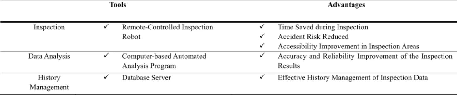
Cable [62]-[66] Table 4. The Main Advantages of Robotics Systems
Tools Advantages Inspection Remote-Controlled Inspection
Robot
Time Saved during Inspection Accident Risk Reduced
Accessibility Improvement in Inspection Areas Data Analysis Computer-based Automated
Analysis Program
Accuracy and Reliability Improvement of the Inspection Results
History Management
Database Server Effective History Management of Inspection Data
Table 5. Robotics System with Image Processing Techniques
Classification Types Research
Robotics System for Bridge Inspection
Special Inspection Vehicle [68], [69] Unmanned Inspection
Robot [10], [70]-[72]
5. DISCUSSION AND CONCLUSION
Most of the highway bridges in the U.S. are inspected using manual visual inspection, but there are several inherent limitations. The manual visual inspection method is influenced by the inspector's knowledge and experience, and the reliability and accuracy of the inspection results can be problematic. In order to overcome this, several robotics system has been applied to inspect the bridge. In this paper, we reviewed the state-of-the-art studies regarding bridge inspection based on robotics system and image processing techniques. These studies on bridge inspection techniques using image processing can be divided into two categories as follows: (i) apparent damage (such as cracks) inspection and (ii) displacement and dynamic characteristics measurements. Presently, much of the research on bridge apparent damage methods using image processing have focused primarily on cracks, and some studies have been extended to spalling and corrosion (Table 3). A bridge's displacement and dynamic response provide valuable information in terms of structural analyses for safety assessment. This information is utilized as the basis data to analyze the performance of the bridge through several system identification methods. Thus, monitoring of the displacement and dynamic characteristic in the bridge is a critical issue for safety and maintenance purposes. The displacement and dynamic response measurements in bridges normally use high precision sensors such as linear variable-differential transformers (LVDTs), accelerometers, and global positioning systems (GPSs). However, such conventional methods have limitations in one form or another [47], [50], [57].
For example, an LVDT or accelerometer needs to be installed with additional equipment such as a data logger (including cable and power supply equipment), which can be both cumbersome and costly when monitoring large-scale bridges. The GPS-based method has low precision in terms of the vertical displacement measurements [80]. The image processing technique uses motion images taken using portable devices such as digital cameras to measure the displacement and natural frequency of a bridge. Such a technique requires no additional equipment (including cables), and measurements at multiple locations can be taken in a relatively shorter time compared to the conventional method.
Consequently, the image processing method can reduce the time and cost compared to the previous sensor-based methods. Image-processing techniques are combined with robotics systems to automate bridge inspection tasks. Generally, robotics based bridge inspection systems are composed of data analysis programs, inspection robots, various sensors and high-resolution cameras. The robotics system acquires reliable bridge inspection results via computer-based analysis programs. In addition, such a system can improve the safety of bridge inspection via the use of inspection robots in dangerous environments. Table 4 describes the main advantages of robotics systems for bridge inspection compared with the conventional inspection methods, and Table 5 summarizes various studies on robotics systems for bridge inspection. The state-of-the-art robotics systems successfully contribute to the automation of bridge inspection.
REFERENCES
[1] B. A. Graybeal, B. M. Phares, D. D. Rolander, M. Moore, and G. Washer, "Visual inspection of highway bridges," Journal of Nondestructive Evaluation, vol. 21, no. 3, 2002, pp. 67-83.
[2] M. R. Jahanshahi, J. S. Kelly, S. F. Masri, and G. S. Sukhatme, "A survey and evaluation of promising approaches for automatic image-based defect detection of bridge structures," Structure and Infrastructure Engineering, vol. 5, no. 6, 2009, pp. 455-486.
[3] H. B. Yun, S. H. Kim, L. L. Wu, and J. J. Lee, "Development of Inspection Robots for Bridge Cables," Scientific World Journal, vol. 2013, 2013.
[4] D. Tenzera, G. Puz, and J. Radic, "Visual inspection in evaluation of bridge condition," Gradevinar, vol. 64, no. 9, 2012, pp. 717-726.
[5] S. N. Laboratories, Visual Inspection : A Review of the Literature, Sandia Report SAND2012-8590, Sandia National Laboratories, Albuquerque, New Mexico, 2012. [6] E. D. Megaw, "Factors Affecting Visual Inspection
Accuracy," Applied Ergonomics, vol. 10, no. 1, 1979, pp. 27-32.
[7] M. Moore, B. M. Phares, B. Graybeal, D. Rolander, and G. Washer, Reliability of visual inspection for highway bridges, volume I: Final report, FHWA Rep. No. FHWA-RD-01-020, FHWA, U.S. Dept. of Transportation, Washington, D.C., 2001.
[8] D. Agdas, J. A. Rice, J. R. Martinez, and I. R. Lasa, "Comparison of visual inspection and structural-health monitoring as bridge condition assessment methods," Journal of Performance of Constructed Facilities, vol. 30, no. 3, 2015, pp. 1-21.
[9] M. Salman and V. Baporikar, "Image based detection and inspection of cracks on bridge surface using an autonomous robot[review]," International Journal on Recent and Innovation Trends in Computing and Communication, vol. 3, no. 2, 2015, pp. 23-27.
[10] R. S. Lim, H. M. La, and W. Sheng, "A robotic crack inspection and mapping system for bridge deck maintenance," IEEE Transactions on Automation Science and Engineering, vol. 11, no. 2, 2014, pp. 367-378. [11] B. Chu, D. Kim, and D. Hong, "Robotic automation
technologies in construction: a review," International Journal of Precision Engineering and Manufacturing, vol. 9, no. 3, 2008, pp. 85-91.
[12] C. Koch, K. Georgieva, V. Kasireddy, B. Akinci, and P. Fieguth, "A review on computer vision based defect detection and condition assessment of concrete and asphalt civil infrastructure," Advanced Engineering Informatics, vol. 29, no. 2, 2015, pp. 196-210.
[13] D. Schmidt and K. Berns, "Climbing robots for maintenance and inspections of vertical structures A survey of design aspects and technologies," Robotics and Autonomous Systems, vol. 61, no. 12, 2013, pp. 1288-1305.
[14] T.D.o. Transportation, Bridge inspection manual, http://onlinemanuals.txdot.gov/txdotmanuals/ins/index.htm.
[15] C.o.F. Regulations, "National Bridge Inspections
Standards Regulation (NBIS)," https://www.fhwa.dot.gov/bridge/nbis.cfm.
[16] D. Rolander, B. Phares, B. Graybeal, M. Moore, and G. Washer, "Highway bridge inspection: State-of-the-practice survey," Transportation Research Record: Journal of the Transportation Research Board, no. 1749, 2001, pp. 73-81. [17] A. Georgopoulos, A. Loizos, and A. Flouda, "Digital
image processing as a tool for pavement distress evaluation," ISPRS Journal of Photogrammetry and Remote Sensing, vol. 50, no. 1, 1995, pp. 23-33.
[18] B. J. Lee and H. Lee, "Position Invariant Neural Network for Digital Pavement Crack Analysis," Computer Aided Civil and Infrastructure Engineering, vol. 19, no. 2, 2004, pp. 105-118.
[19] O. Abudayyeh, M. Al Bataineh, and I. Abdel-Qader, "An imaging data model for concrete bridge inspection," Advances in Engineering Software, vol. 35, no. 8, 2004, pp. 473-480.
[20] T. C. Hutchinson and Z. Chen, "Improved image analysis for evaluating concrete damage," Journal of Computing in Civil Engineering, vol. 20, no. 3, 2006, pp. 210-216. [21] L. Abdel-Qader, O. Abudayyeh, and M. E. Kelly,
"Analysis of edge-detection techniques for crack identification in bridges," Journal of Computing in Civil Engineering, vol. 17, no. 4, 2003, pp. 255-263.
[22] I. Abdel-Qader, S. Pashaie-Rad, O. Abudayyeh, and S. Yehia, "PCA-based algorithm for unsupervised bridge crack detection," Advances in Engineering Software, vol. 37, no. 12, 2006, pp. 771-778.
[23] T. Yamaguchi and S. Hashimoto, "Image processing based on percolation model," Ieice Transactions on Information and Systems, vol. E89d, no. 7, 2006, pp. 2044-2052. [24] T. Yamaguchi and S. Hashimoto, "Fast crack detection
method for large-size concrete surface images using percolation-based image processing," Machine Vision and Applications, vol. 21, no. 5, 2010, pp. 797-809.
[25] Y. Fujita and Y. Hamamoto, "A robust automatic crack detection method from noisy concrete surfaces," Machine Vision and Applications, vol. 22, no. 2, 2011, pp. 245-254. [26] B. Y. Lee, Y. Y. Kim, S. T. Yi, and J. K. Kim, "Automated image processing technique for detecting and analysing concrete surface cracks," Structure and Infrastructure Engineering, vol. 9, no. 6, 2013, pp. 567-577.
[27] X. Tong, J. Guo, Y. Ling, and Z. Yin, "A new image-based method for concrete bridge bottom crack detection," 2011 International Conference on Image Analysis and Signal Processing, 2011, pp. 568-571.
[28] G. Bu, S. Chanda, H. Guan, J. Jo, M. Blumenstein, and Y. Loo, "Crack Detection using a Texture Analysis-based Technique for Visual Bridge Inspection," Electronic Journal of Structural Engineering, vol. 14, no. 1, 2015. [29] H. G. Sohn, Y. M. Lim, K. H. Yun, and G. H. Kim,
"Monitoring crack changes in concrete structures," Computer-Aided Civil and Infrastructure Engineering, vol. 20, no. 1, 2005, pp. 52-61.
[30] L. C. Chen, Y. C. Shao, H. H. Jan, C. W. Huang, and Y. M. Tien, "Measuring system for cracks in concrete using
multitemporal images," Journal of Surveying Engineering-Asce, vol. 132, no. 2, 2006, pp. 77-82.
[31] K. Ehrig, J. Goebbels, D. Meinel, O. Paetsch, S. Prohaska, and V. Zobel, "Comparison of crack detection methods for analyzing damage processes in concrete with computed tomography," International Symposium on Digital Industrial Radiology and Computed Tomography, Berlin, Germany P, vol. 2, 2011.
[32] Y. S. Yang, C. M. Yang, and C. W. Huang, "Thin crack observation in a reinforced concrete bridge pier test using image processing and analysis," Advances in Engineering Software, vol. 83, 2015, pp. 99-108.
[33] M. R. Jahanshahi and S. F. Masri, "Adaptive vision-based crack detection using 3D scene reconstruction for condition assessment of structures," Automation in Construction, vol. 22, 2012, pp. 567-576.
[34] M. R. Jahanshahi and S. F. Masri, "A new methodology for non-contact accurate crack width measurement through photogrammetry for automated structural safety evaluation," Smart materials and structures, vol. 22, no. 3, 2013, p. 035019.
[35] Z. Zhu, S. German, and I. Brilakis, "Detection of large-scale concrete columns for automated bridge inspection," Automation in Construction, vol. 19, no. 8, 2010, pp. 1047-1055.
[36] S. German, I. Brilakis, and R. DesRoches, "Rapid entropy-based detection and properties measurement of concrete spalling with machine vision for post-earthquake safety assessments," Advanced Engineering Informatics, vol. 26, no. 4, 2012, pp. 846-858.
[37] R. S. Adhikari, O. Moselhi, and A. Bagchi, "A study of Image-based Element Condition Index for Bridge Inspection," FUTURE, 2013.
[38] S. Lee, L. M. Chang, and M. Skibniewski, "Automated recognition of surface defects using digital color image processing," Automation in Construction, vol. 15, no. 4, 2006, pp. 540-549.
[39] P. H. Chen, H. K. Shen, C. Y. Lei, and L. M. Chang, "Support-vector-machine-based method for automated steel bridge rust assessment," Automation in Construction, vol. 23, 2012, pp. 9-19.
[40] G. Stephen, J. Brownjohn, and C. Taylor, "Measurements of static and dynamic displacement from visual monitoring of the Humber Bridge," Engineering Structures, vol. 15, no. 3, 1993, pp. 197-208.
[41] P. Olaszek, "Investigation of the dynamic characteristic of bridge structures using a computer vision method," Measurement, vol. 25, no. 3, 1999, pp. 227-236.
[42] D. V. Jáuregui, K. R. White, C. B. Woodward, and K. R. Leitch, "Noncontact photogrammetric measurement of vertical bridge deflection," Journal of Bridge Engineering, vol. 8, no. 4, 2003, pp. 212-222.
[43] U. Poudel, G. Fu, and J. Ye, "Structural damage detection using digital video imaging technique and wavelet transformation," Journal of Sound and Vibration, vol. 286, no. 4, 2005, pp. 869-895.
[44] G. Fu and A. G. Moosa, "An optical approach to structural displacement measurement and its application," Journal of Engineering Mechanics, vol. 128, no. 5, 2002, pp. 511-520. [45] A. M. Wahbeh, J. P. Caffrey, and S. F. Masri, "A
vision-based approach for the direct measurement of displacements in vibrating systems," Smart Materials and Structures, vol. 12, no. 5, 2003, p. 785.
[46] P. Kohut, K. Holak, T. Uhl, Ł. Ortyl, T. Owerko, P. Kuras, and R. Kocierz, "Monitoring of a civil structure’s state based on noncontact measurements," Structural Health Monitoring, vol. 12, no. 5-6, 2013, pp. 411-429.
[47] J. J. Lee and M. Shinozuka, "Real-time displacement measurement of a flexible bridge using digital image processing techniques," Experimental mechanics, vol. 46, no. 1, 2006, pp. 105-114.
[48] J. J. Lee and M. Shinozuka, "A vision-based system for remote sensing of bridge displacement," Ndt & E International, vol. 39, no. 5, 2006, pp. 425-431.
[49] J. J. Lee, M. Shinozuka, and C. G. Lee, "Evaluation of bridge load carrying capacity based on dynamic displacement measurement using real-time image processing techniques," International Journal of Steel Structures, vol. 6, no. 5, 2006, pp. 377-385.
[50] Y. Fukuda, M. Q. Feng, and M. Shinozuka, "Cost effective vision based system for monitoring dynamic response of civil engineering structures," Structural Control and Health Monitoring, vol. 17, no. 8, 2010, pp. 918-936.
[51] H. S. Choi, J. H. Cheung, S. H. Kim, and J. H. Ahn, "Structural dynamic displacement vision system using digital image processing," NDT & E International, vol. 44, no. 7, 2011, pp. 597-608.
[52] H. N. Ho, J. H. Lee, Y. S. Park, and J. J. Lee, "A synchronized multipoint vision-based system for displacement measurement of civil infrastructures," The Scientific World Journal, vol. 2012, 2012.
[53] L. Tian and B. Pan, "Remote Bridge Deflection Measurement Using an Advanced Video Deflectometer and Actively Illuminated LED Targets," Sensors, vol. 16, no. 9, 2016, p. 1344.
[54] S. Yoneyama, A. Kitagawa, S. Iwata, K. Tani, and H. Kikuta, "Bridge deflection measurement using digital image correlation," Experimental Techniques, vol. 31, no. 1, 2007, pp. 34-40.
[55] G. Busca, A. Cigada, P. Mazzoleni, and E. Zappa, "Vibration Monitoring of Multiple Bridge Points by Means of a Unique Vision-Based Measuring System," Experimental Mechanics, vol. 54, no. 2, 2014, pp. 255-271. [56] D. M. Feng, M. Q. Feng, E. Ozer, and Y. Fukuda, "A
Vision-Based Sensor for Noncontact Structural Displacement Measurement," Sensors, vol. 15, no. 7, 2015, pp. 16557-16575.
[57] D. Ribeiro, R. Calcada, J. Ferreira, and T. Martins, "Non-contact measurement of the dynamic displacement of railway bridges using an advanced video-based system," Engineering Structures, vol. 75, 2014, pp. 164-180. [58] M. Q. Feng, Y. Fukuda, D. Feng, and M. Mizuta,
"Nontarget vision sensor for remote measurement of
bridge dynamic response," Journal of Bridge Engineering, vol. 20, no. 12, 2015, p. 04015023.
[59] H. Jeon, Y. Bang, and H. Myung, "A paired visual servoing system for 6-DOF displacement measurement of structures," Smart Materials and Structures, vol. 20, no. 4, 2011, p. 045019.
[60] S. Park, H. Park, J. Kim, and H. Adeli, "3D displacement measurement model for health monitoring of structures using a motion capture system," Measurement, vol. 59, 2015, pp. 352-362.
[61] C. Chang and X. Xiao, "Three-dimensional structural translation and rotation measurement using monocular videogrammetry," Journal of engineering mechanics, vol. 136, no. 7, 2009, pp. 840-848.
[62] Y. Ji and C. Chang, "Nontarget image-based technique for small cable vibration measurement," Journal of Bridge Engineering, vol. 13, no. 1, 2008, pp. 34-42.
[63] Y. Ji and C. Chang, "Nontarget stereo vision technique for spatiotemporal response measurement of line-like structures," Journal of engineering mechanics, vol. 134, no. 6, 2008, pp. 466-474.
[64] S. W. Kim and N. S. Kim, "Dynamic characteristics of suspension bridge hanger cables using digital image processing," NDT & E International, vol. 59, 2013, pp. 25-33. [65] B. H. Kim, "Extracting modal parameters of a cable on
shaky motion pictures," Mechanical Systems and Signal Processing, vol. 49, no. 1, 2014, pp. 3-12.
[66] C. C. Chen, W. H. Wu, H. Z. Tseng, C. H. Chen, and G. Lai, "Application of digital photogrammetry techniques in identifying the mode shape ratios of stay cables with multiple camcorders," Measurement, vol. 75, 2015, pp. 134-146. [67] R. Montero, J. G. Victores, S. Martinez, A. Jardon, and
C. Balaguer, "Past, present and future of robotic tunnel inspection," Automation in Construction, vol. 59, 2015, pp. 99-112.
[68] P. C. Tung, Y. R. Hwang, and M. C. Wu, "The development of a mobile manipulator imaging system for bridge crack inspection," Automation in Construction, vol. 11, no. 6, 2002, pp. 717-729.
[69] J. K. Oh, G. Jang, S. Oh, J. H. Lee, B. J. Yi, Y. S. Moon, J. S. Lee, and Y. Choi, "Bridge inspection robot system with machine vision," Automation in Construction, vol. 18, no. 7, 2009, pp. 929-941.
[70] B. J. Lee, H. T. Kang, J. I. Shin, and C. H. Park, "The Scientific Inspection Method for a PSC Box Bridge Using a Remote-Control Tarantula Robot," 13th Conference of REAAA, 2009.
[71] H. M. La, R. S. Lim, B. B. Basily, N. Gucunski, J. Yi, A. Maher, F. A. Romero, and H. Parvardeh, "Mechatronic systems design for an autonomous robotic system for high-efficiency bridge deck inspection and evaluation," IEEE/ASME Transactions on Mechatronics, vol. 18, no. 6, 2013, pp. 1655-1664.
[72] S. Gibb, H. M. La, T. Le, L. Nguyen, R. Schmid, and H. Pham, "Nondestructive evaluation sensor fusion with autonomous robotic system for civil infrastructure inspection," Journal of Field Robotics, 2018, pp. 1-17. https://doi.org/10.1002/rob.21791.
[73] C. Hillenbrand, D. Schmidt, and K. Berns, "CROMSCI: development of a climbing robot with negative pressure adhesion for inspections," Industrial Robot-an International Journal, vol. 35, no. 3, 2008, pp. 228-237. [74] A. Mazumdar and H. H. Asada, "An Underactuated,
Magnetic-Foot Robot for Steel Bridge Inspection," Journal of Mechanisms and Robotics-Transactions of the Asme, vol. 2, no. 3, 2010.
[75] R. Wang and Y. Kawamura, "An Automated Sensing System for Steel Bridge Inspection Using GMR Sensor Array and Magnetic Wheels of Climbing Robot," Journal of Sensors, vol. 2016, 2016, pp. 1-15.
[76] Y. Luo, S. R. Xie, Z. B. Gong, and T. S. Lu, "Development of cable maintenance robot for cable-stayed bridges," Industrial Robot-an International Journal, vol. 34, no. 4, 2007, pp. 303-309.
[77] F. Y. Xu, X. S. Wang, and L. Wang, "Cable Inspection Robot for Cable-Stayed Bridges: Design, Analysis, and Application," Journal of Field Robotics, vol. 28, no. 3, 2011, pp. 441-459.
[78] K. H. Cho, H. M. Kim, Y. H. Jin, F. Liu, H. Moon, J. C. Koo, and H. R. Choi, "Inspection Robot for Hanger Cable of Suspension Bridge: Mechanism Design and Analysis," Ieee-Asme Transactions on Mechatronics, vol. 18, no. 6, 2013, pp. 1665-1674.
[79] H. M. La, T. H. Dinh, N. H. Pham, Q. P. Ha, and A. Q. Pham, "Automated robotic monitoring and inspection of steel structures and bridges," Robotica, 2018, pp. 1-21. https://doi.org/10.1017/S0263574717000601.
[80] P. Psimoulis, S. Pytharouli, D. Karambalis, and S. Stiros, "Potential of Global Positioning System (GPS) to measure frequencies of oscillations of engineering structures," Journal of Sound and Vibration, vol. 318, no. 3, 2008, pp. 606-623.
Byung-Wan Jo
He received the B.S., M.S in civil engineering from Hanyang University, Korea and Ohio State University respectively. Also he received Ph.D in civil engineering from Florida University in 1988. Currently he is working at Hanyang University as Professor. His main research interests include structural monitoring, sensors.
Yun-Sung Lee
He received the M.S in civil engineering from Hanyang University, Korea in 2011. Currently he is working at Hanyang University as Ph.D candidate. His main research interests include structural monitoring, sensors.
Jung-Hoon Kim
He received the B.S. in Civil engineering from Rensselaer Polytechnic Institute, USA in 2015. Currently he is working at Hanyang University as Ph.D candidate. His main research interests include reinforced concrete structure monitoring, and 3D printed structures.
Kwang-Won Yoon
He received the Ph.D in structural engineering from Hanyang University, Korea in 2015. Since then, he has been working with the Safety management division of Seoul Metropolitan Government. His main research interests include improvement of the safety management for infra structure.
![Table 1. Major Standards and Manuals in the United States. The Table is Modified from [14]](https://thumb-ap.123doks.com/thumbv2/123dokinfo/5004535.59074/2.892.75.819.666.920/table-major-standards-manuals-united-states-table-modified.webp)