ABSTRACT
In general, the forklift driven by DC motor drive system is used in the industrial field. Classically, the DC motor is controlled by current control using proportion control method, by output torque following the load on the plane like a manual operation. But in the industrial field, the forklift is demanded the robust drive mode. Some cases of the mode, there aretrouble in torque control following slope capacity. The control is sensitive concerning about slope angle and output speed, various control method is studied for stability of speed control. In this paper, I apply current control for the self-tuning using the fuzzy controller to obtain robust, stable speed control and use stable, high efficiency control using DSP as main controller for high speed processor, embody dynamic characteristic of control compared the PI controller to the fuzzy controller.
1. INTRODUCTION
Adaptive control which adjusts gain of PID controller according to change in a system is used in order to control of the forklift. Under this adaptive control, however, it is practically hard to make an efficient controller due to complication of algorithm and any other reason. Also Variable Structure Control is applied as a nonlinearity control but it might cause high frequency characteristics disregarding high speed modeling on a sliding surface. In order to solve this problem the fuzzy controller with self-tuning is applied, which will perform high efficiency speed control. The efficiency of control algorithm is presented through a experiment and compared with the quality of PID controller.
2. METHOD
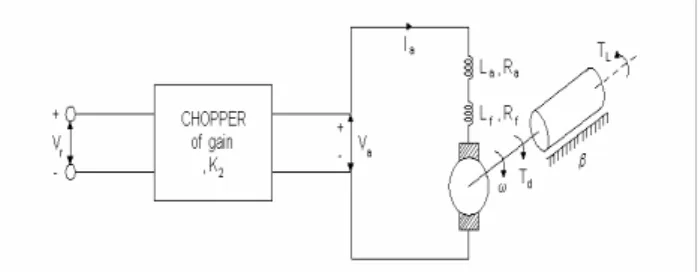
2.1 DC motor in transfer functionDC motor in the forklift needs huge force of traction , which steady-state speed is determined by friction and force of traction. And rated speed of the motor, the highest terminal voltage, is controlled in a uniform current by regulating terminal voltage.
Fig. 1 Chopper-fed DC motor drive
As Fig. 1 indicates, the terminal voltage is related with the
standard voltage on chopper's linearity gain k2. Supposing that
kv, electromotive force coefficient is fixed regardless of armature current, the DC motor equation for motor system including load is induced as a formula,
V
a=
K
2V
r,
e
g=
K
vi
aω
g a m a m ae
dt
di
L
i
R
V
=
+
+
(1)T
d=
K
ti
a2 L dB
T
dt
d
J
T
=
ω
+
ω
+
(2)In equation Td = kt * ia2, it is characteristic of variable type
nonlinear, controller is designed on limited range of operation transforming the nonlinearity system into the linearity system on the purpose of applying transfer function. So define system parameters at operating point as follows,
g go g
E
e
e
=
+
∆
,i
a=
I
ao+
∆
i
a a ao aV
v
v
=
+
∆
,T
d=
T
do+
∆
T
d (3)ω
ω
ω
=
o+
∆
,v
r=
V
ro+
∆
v
r L Lo LT
T
T
=
+
∆
(4)where, we can find that are entirely small.
The equation (2) from equation (1) can be linearization as follows.
Current Control of the Forklift using a Fuzzy Controller
Jong Il Bae*
* Dept. of Electrical Engineering, Pukyong National University, Pusan 608-739, Korea
Tel : 82-51-620-1437, Fax : 82-51-620-1437
E-mail : [email protected]
)
(
2 r g v ao o a aK
v
e
K
I
i
v
=
∆
∆
=
∆
+
∆
∆
ω
ω
(5) g m a m aB
e
dt
d
L
i
R
v
=
+
∆
+
∆
∆
(
ω
)
(6) a ao v dK
I
I
T
=
∆
∆
2
L dB
T
dt
d
J
T
=
∆
+
∆
+
∆
∆
(
ω
)
ω
(7)Which are written in the transform of Laplace space as follows.
)
(
)
(
s
K
2V
s
V
a=
∆
r∆
(8))]
(
)
(
[
)
(
s
K
I
s
I
s
E
g=
v ao∆
+
o∆
a∆
ω
ω
(9))
(
)
(
)
(
)
(
s
R
I
s
sL
I
s
E
s
V
a=
m∆
a+
m∆
a+
∆
g∆
(10))
(
2
)
(
s
K
I
I
s
T
d=
v ao∆
a∆
(11))
(
)
(
)
(
)
(
s
sJ
s
B
s
T
s
T
d=
∆
+
∆
+
∆
L∆
ω
ω
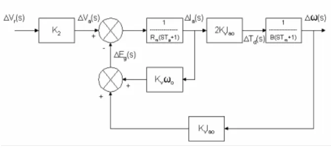
(12)Which mean that the change of either reference voltage or load torque is the change of speed block diagram for the change of reference voltage and load torque is drawn in Fig. 2 and Fig. 3
Fig. 2 Block diagram for reference voltage
Fig. 3 Block diagram for load torque disturbances
2.2 Current controller with closed transfer function
We can get the dynamic equation of the motor as Kirchhoff's voltage equation is applied to armature field system circuits and easily obtain the dynamic equation through Newton's dynamic laws that are applied to rotation-machinery part as the electrical and mechanical combined relation equation is applied to motor current and generation torque.
In section 2.1, current sensor is connected to power circuit to convert closed-loop system, so the output sensor is amplified in proportion to supply current of rotor by α-factor and generates
error voltage (
∆
ε
) comparing it with current (∆
I
c(s
)
)(a) Block diagram of DC motor
(b) Simple block diagram Fig. 4 Closed-loop block diagram of DC motor
(1) Let us solve that closed-loop step response(∆ω(s)) caused change of reference current in the block diagram
=
∆
∆
)
(
)
(
s
I
s
cω
2 2 2 2)
(
)
(
)
(
)
)(
(
2
)
(
ao v o v m m ao vI
sK
sJ
B
K
sJ
B
K
N
sJ
B
sL
R
I
K
K
N
+
+
+
+
+
+
+
ε
α
ω
ε
according to final value theorem
)
)
(
(
2
)
(
)
(
)
(
lim
2 2B
K
B
K
N
B
R
I
K
K
N
s
I
s
o v m ao v c o sε
α
ω
ε
ω
+
+
=
∆
∆
→(2) Speed change in normal operating-∆ω(s)
2 2 2 2
2
)
)
(
(
)
(
)
(
)
(
lim
ao v o v m o v L o sB
R
K
N
K
K
I
K
N
K
R
s
T
s
+
+
+
+
+
=
∆
∆
→ε
ω
ω
α
ε
ω
=
∆
∆
)
(
)
(
s
T
s
Lω
2 2 2 22
]
)
(
)
)[(
(
)
(
)
(
ao v o v m m o v m mI
K
K
N
K
sL
R
Js
B
K
N
K
sL
R
+
+
+
+
+
+
+
+
ω
α
ε
ω
α
ε
2.3 Self-tuning of the fuzzy controller
Fig.5 shows the hardware diagram for tuning membership function of the fuzzy controller. IBM PC tune membership function of the fuzzy controller. 818 Lab card will transfer a signal and DSP board will control current.
Fig. 5 The hardware diagram for magnetic tuning the fuzzy controller using PC
3. THE CURRENT CONTROL OF DC
MOTOR USING DSP (TMS320F240).
3.1 Configuration of the hardware.
We use the PI current controller for internal loop to control DC motor as Fig. 6. Configuration of hardware system shows in the Fig.7. The Internal loop consists of the current controller, PWM module, motor driver circuit and current sensor. The external loop consists of the current controller. As the Fig. 8, the current controller changes current commend every 5[msec]. Setups about interrupt, PWM follow the one of PI current controller.
Fig. 6 The hardware diagram for current control of real system
Fig. 7 The hardware diagram for speed control of DC motor
3.2 The current control using PI controller.
(1) The architecture of controller.
It is possible to control of the PI controller in the Fig 8. The input value of current control is the gap between reference speed command and feedback value from the tachometer. Out put value is current command from the current controller which is internal loop. The equation used in the PI controller is the equation (13).
dt
e
k
e
k
u
=
P×
+
I×
∫
t
e
k
e
k
P×
+
I×
⋅
∆
=
∑
(13) It is possible to remove the noise from the tachometer, current sensor and potentiometer by taking five simple moving mean value using speed information every 5[msec], current every 1[msec] and pedal every 1[msec].
The moving mean method correspond with digital low pass filter and represented the equation (14). If weight is uniform, it can be simple movement mean method.
∑
− =+
=
1
0(
)
(
)
)
(
m jj
i
x
j
w
i
y
ω
(14)(2) The control of PI controller gain
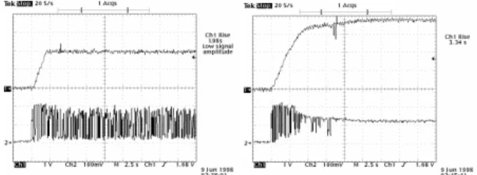
At the graph of test results, the speed response of the top side is that 1[V] shows 500[rpm] and the current of the low side means that 1[V] shows 100[A].
X
* EVIVRB==0x002f
Read ADC for Current Sensor 1 Yes No Yes Yes No
Current control per 5 ms .
Current control per 1 ms seek for Current Sensor1 value
search the Interrupt Vecto and
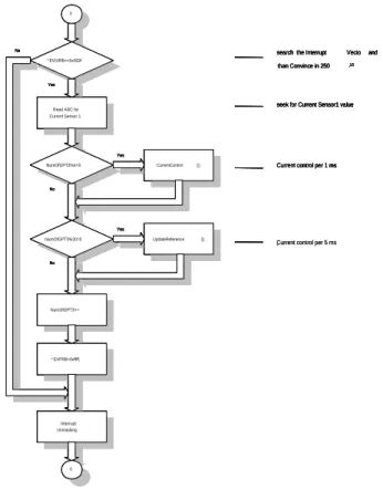
than Convince in 250 ㎲ No NumOfGPT3%4=0 CurrentControl (); NumOfGPT3%20=0 UpdateReference (); NumOfGPT3++ * EVFRB=0xffff; Interrupt Unmasking X X * EVIVRB==0x002f
Read ADC for Current Sensor 1 Yes No Yes Yes No .
Current control per 1 ms seek for Current Sensor1 value
search the Interrupt Vecto and
than Convince in 250 ㎲ No NumOfGPT3%4=0 CurrentControl (); NumOfGPT3%20=0 UpdateReference (); NumOfGPT3++ * EVFRB=0xffff; Interrupt Unmasking X X * EVIVRB==0x002f
Read ADC for Current Sensor 1 Yes No Yes Yes No
Current control per 5 ms .
Current control per 1 ms seek for Current Sensor1 value
search the Interrupt Vecto and
than Convince in 250 ㎲ No NumOfGPT3%4=0 CurrentControl (); NumOfGPT3%20=0 UpdateReference (); NumOfGPT3++ * EVFRB=0xffff; Interrupt Unmasking X X * EVIVRB==0x002f
Read ADC for Current Sensor 1 Yes No Yes Yes No .
Current control per 1 ms seek for Current Sensor1 value
search the Interrupt Vecto and
than Convince in 250 ㎲ No NumOfGPT3%4=0 CurrentControl (); NumOfGPT3%20=0 UpdateReference (); NumOfGPT3++ * EVFRB=0xffff; Interrupt Unmasking X
Fig. 8 Flow chart of 250[㎲] interrupt subprogram The current scale of downward oscilloscope channel 2 means that 100[mV] represents 1[V/div]. It shows the load of the weight of the forklift body concerning that load becomes 100[A] and the 160[A]. Load shows the load of weights of the forklift body and something loaded.
a) Response in changing a proportional gain
At the Fig. 9, the response is showed as
k
P changes whenspeed command value
k
I,k
P are equal to 1500[rpm], 1,100[A] respectively.
b) Response in changing an integral gain
Fig.10 shows response of changing
k
I when speed commandvalue is 1500[rpm],
k
P is 5.0 and load is 100[A].(3) Result of Test
When load is being at 100[A], Fig. 11 shows the response of
changing reference speed at
k
P= 5.0,
k
I= 0.5Due to such limits, the wrong response appears like steady-state error and the asymptotic slope increases with keeping the load in 160[A].
(a)
I
k
= 0.1 (b)k
I= 4.0(
k
I= 1, load 100[A], reference speed 1500[rpm])(a)
I
k
= 0.1 (b)k
I= 4.0(
k
I= 1, load 100[A], reference speed 1500[rpm])Fig. 10 Experiment results 2 of PI controller
(a) Reference speed 1000[rpm] (b) Reference speed 2500[rpm]
Fig. 11 Experiment results of PI controller when load 100[A] (max. 200[A])
3.3 Current control using the fuzzy controller 3.3.1 Configuration of controller
We constitute the fuzzy controller from speed controller in Fig. 7 for speed control. Inputs of the fuzzy controller become the reference command value, the error and the change ratio of the feedback speed value from tachometer, so output has the command value of reference current of current controller like initial loop.
3.3.2 Current control of the fuzzy controller of using tuned belonging function
As we consider the condition used for the fuzzy controller of fuzzy rule uses the value in Table 1 based on phase plane and belonging function uses the value in Table 2 tuned by a genetic Algorithm. Because all the belonging functions in Table 2 are normalized, we need scale values, so let's speed error scale, error change rate and output go to 0.5, 1.0 and 2.5 respectively. Here, speed error and error change rate mean 500[rpm] when they are 1.0 and output means 100[A] when it is 1.0.
Table 1 Table of 49 control rules e Δe NB NM NS ZO PS PM PB NB NB NB NB NB NM NS ZO NM NB NB NB NM NS ZO PS NS NB NB NM NS ZO PS PM ZO NB NM NS ZO PS PM PB PS NM NS ZO PS PM PB PB PM NS ZO PS PM PB PB PB PB ZO PS PM PB PB PB PB Language Value NB : Negative big, NM : Negative medium, NS : Negative small, PS : Positive small PU : Positive medium PB : Positive big
Table 2 Belonging function of tuning the fuzzy controller
Kind NB NM NS ZO PS PM PB
e -1.00 -0.42 -0.08 0.00 0.03 0.21 1.00
Δe -1.00 -0.61 -0.25 0.00 0.31 0.74 1.00
u -1.00 -0.62 -0.35 0.00 0.32 0.57 1.00
(1) Test when load 100[A]
a) Classification the fuzzy controller
The result is showed in Fig. 12 when the fuzzy controller with self-tuning belonging function is executed by a genetic algorithm and load is 100[A]. Here, the speed information is the value from five moving mean method every 5[msec] and we get error and error rate by using that. As the response, steady-state error doesn't occur at reference speed of 1000[rpm] and the asymptotic slope to steady state reaches zero.
But steady state error occurs at 2000[rpm] because output fuzzy scale doesn't match.
(a) Reference speed 1000[rpm](b) Reference speed 2000[rpm] Fig. 12 Outputs of basic fuzzy controller (load 100[A]) b) The fuzzy controller using fuzzy singleton.
The fuzzy singleton generates ON-OFF signal not like general fuzzy group. The Fig 13(a) shows that the quick response becomes slow because of the fuzzy controller from the transition response. The Fig 22(b) represent that the quick response time is improved comparing with existing fuzzy controller and steady-state error, asymptotic slope disappear.
(a) Reference speed 1000[rpm](b) Reference speed 2000[rpm] Fig. 13 The fuzzy controller output using fuzzy singleton
(load 100[A])
c) The fuzzy controller using individual moving mean method. We get speed error and error rate from five moving mean value every 5[msec] using fuzzy singleton. Individual means taking five moving mean every 5[msec] from the speed information and error rate every 1[msec]. The speed error can be taken from the moving mean of speed information. As the
response, quick response improves much at the reference speed 1000[rpm] but the steady-state error occurs at 2000[rpm]. because of not matching output fuzzy scale as the Fig. 14(a).
(a) Reference speed 1000[rpm](b) Reference speed 2000[rpm] Fig. 14 Outputs of the fuzzy controller using individual moving
Mean method (load 100[A])
3.3.3 Result of the test
A steady-state error was not generated if a clause in some degree is satisfied in the fuzzy controller.
Fig. 15 shows quick responses of an each the fuzzy controller at load 100[A], different reference speed. So responses using individual method show very good. The fuzzy controller using individual moving method was not converged because out put scale is small in the response of 2000[rpm].
Fig. 16 shows quick responses of the fuzzy controller using individual moving method when load is defined 100[A].
Fig. 15 Quick response each reference speed (load 100[A])
(a) load 100[A], reference speed 500[rpm]
(c) load 100[A], reference speed 1000[rpm] Fig. 16 Responses of the fuzzy controller using individual
moving method
4. RESULT
When load changes, the fuzzy controller didn't need tuned belonging function to be recontrolled and meeted with the change of the load only as controlling output scale.
The fuzzy controller influences the change rate of error as noise exists in speed feedback , so current ripple occurs. In this paper, We apply the simple moving mean method and the individual moving mean method to decrease the effect of the noise. The result shows that the individual moving mean method is most effective performance. We need more study of the PI type fuzzy controller to decrease current ripple occurring at the fuzzy controller.
Table 3 is comparison of PI controller response when reference speed is 1000[rpm], the load is 100[A], and response of the fuzzy controller using individual moving method. It shows the fuzzy controller is better quick response and characteristics of steady-state than PI controller.
Table 3 Result comparison of PI controller and the fuzzy controller(reference speed 1000[rpm])
5. REFERENCE
[1] G. C. D. Sousa and B. K. Bose, “A fuzzy set theory based control of a phase controlled converter DC machine drive,” Conf. Rec, IEEE IAS Ann. Meeting, pp. 854-861, October, 1991
[2] Sang-Rae Lee and Kwang-Won Lee, “A new variable structure position control for DC motor using fuzzy logic,” KIEE Trans, Vol. 41, No. 6, pp. 625-632, 1992
[3] TMS320C24X DSP Controllers Reference Set-Volume 1, Texas Instruments, 1997
[4] TMS320C24X DSP Controllers Reference Set-Volume 2, Texas Instruments, 1997
[5] Chae-suk, Young-Sik Oh, Fuzzy Theory and Control, Chung Moon Kag, 1995
[6] Rainer Palm, Dimiter Driankov, Hans Hellendoorn, Model Based Fuzzy Control, Springer, 1997
[7] David B. fogel, Evolutionary Computation, IEEE PRESS, 1995
[8] TMS320C2x/C2xx/C5x Optimizing C Compiler-User's Guide, Texas Instrument, 1995
[9] Dimiter Driankov, Hans Hellendoorn, Michael Reinfrank, An Introduction to Fuzzy Control, Springer, 1996 [10] TMS320C5x C Source Debugger-User's Guide, Texas
Instrument, 1994
[11] TMS320C1x/C2x/C2xx/C5x Assembly Language Tools-User's Guide, Texas Instrument, 1995
[12] B. Kosko, Neural Networks and Fuzzy Systems, Prentice Hall, 1992
PI controller Fuzzy controller Controller
Function 100[A] 100[A]
Rising time [sec] 0.825 0.670
Steady State error [rpm] 20 0
![Fig. 15 shows quick responses of an each the fuzzy controller at load 100[A], different reference speed](https://thumb-ap.123doks.com/thumbv2/123dokinfo/4893734.37493/5.892.78.422.171.296/shows-quick-responses-fuzzy-controller-different-reference-speed.webp)
