__ICCAS2005____________________________________ _June 2-5, KINTEX, Gyeonggi-Do, Korea__
Invariant Range Image Multi-Pose Face Recognition Using Fuzzy c-Means
Pisit Phokharatkul
1, Seri Pansang
21Department of Computer Engineering, Faculty of Engineering, Mahidol University
Salaya, Phutthamonthon 4 Road, Phutthamonthon, Nakhon Pathom, 73170, Thailand. Email: [email protected],
2Department of Computer Science, Faculty of Science, Rajabhat Chiang Mai University
Chiang Mai, 50300, Thailand. Email: [email protected]
Abstract: In this paper, we propose fuzzy c-means (FCM) to solve recognition errors in invariant range image, multi-pose face
recognition. Scale, center and pose error problems were solved using geometric transformation. Range image face data was digitized into range image data by using the laser range finder that does not depend on the ambient light source. Then, the digitized range image face data is used as a model to generate multi-pose data. Each pose data size was reduced by linear reduction into the database. The reduced range image face data was transformed to the gradient face model for facial feature image extraction and also for matching using the fuzzy membership adjusted by fuzzy c-means. The proposed method was tested using facial range images from 40 people with normal facial expressions. The output of the detection and recognition system has to be accurate to about 93 percent. Simultaneously, the system must be robust enough to overcome typical image-acquisition problems such as noise, vertical rotated face and range resolution.
Keywords: Multi-pose face recognition, Facial range image, Gradient transformation, Geometric transformation and fuzzy c- means.
1. INTRODUCTION
After the terrorist attacks, which occurred in the US on September 11th 2001, there have been increases in demands for effective security systems. Security measures were implemented in the airports, including the use of face recognition. But these systems, which have been implemented, are not 100 % accurate. In the case of face recognition, there are two major problems to identify a person from an image of their face. Firstly, problems occur from environmental light noise, position of the image size, and variation of pose. These problems are difficult to control. Secondly, problems arise in face variations from person to person, such as facial expressions, posture, hairstyle, facial hair, aging, makeup, and eyeglasses.
Related research has found that most face recognition systems focus on a single pose [1-4]. Pose variation problems occur in single pose face recognition models when the pose position of the test Range Image Face Data (RIFD) was changed from the pose database value. Furthermore, single pose face recognition has not worked flexibly with variation of pose in the past and continues to be a problem.
This research proposes invariant range image multi-pose face recognition using FCM to recognize identity despite such variations in appearance that the face can have. The techniques use fuzzy c-means clustering to adjust ambiguity freely of various range image face data (RIFD). FCM is based on fuzzy c-partitions, where c designates the number of fuzzy classes in the partition [5].
The human face is digitized into the range image data by using a laser range finder that is less sensitive to changes in environmental light [6-8]. Since the wavelength of a laser beam is different from the wavelength of conventional light, it is easy to capture a laser image for calculating a range with simple triangular techniques. Digitized RIFD is used as a model to generate multi-pose RIFD by using geometric transform. Linear reduction is used to reduce each pose image data size. Gradient Transform is used to extract features from the data. The data is reduced again by ellipse
face region extraction [9] and finally the features are stored in a multi-pose database.
2. OVERVIEW OF THE SYSTEM
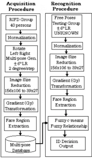
The overview of the face recognition system is illustrated in Figure1. There are two procedures in this system; acquisition and recognition.
In the acquisition procedure, the faces of each test subject that the system is required to acknowledge are added to the RIFD database. The human face is digitized into the range image data by using the laser range finder [10]. The size is adjusted to 158×108 pixels with a range resolution of ± 1mm. The region of RIFD covers the area of about 240×166 sq.mm. This face size is the average for most Asian people. For each
RIFD input, acquisition, scale and center are varied each time,
which directly affects the recognition rate. Since these parameters are difficult to control, it is necessary for normalization to adjust the parameters of all RIFD to the standard value.
In the recognition procedure, it is similar to the acquisition procedure; however, the difference is shown in the lack of multi-pose generating block diagrams. The RIFD input for testing was assigned to the independent pose position with the range of ±6 degrees left/right (LR) from normal poses. However, the difficulty is not knowing which pose position will be selected as the test face pose. This system is designed for covering all the ranges, with all poses of each person. Since FCM is collaborating with fuzzy relationship, which was created for searching the best similarity in the multi-pose database, it is unnecessary to process all RIFD matching in the database. The highest similarity pose of each test subject is searched for at the ID decision output as shown in the last block of Figure 1. The system that is shown is quite simple, but it is applicable.
3. ACQUISITION PROCEDURE 3.1 Normalization [11-12]
Because the range image matrix is based on 3D graphics, the geometric transform [13] is used to normalize and solve the variation pose problem. By using Equation (1), the normalization and rotation of the pose position is combined.
V
*=
T
0−1(
R
(
T
0(
T
C(
S
×
V
))))
(1) TZ
Y
X
*
*
*
1
)
(
=
(2) TZ
Y
X
V
=
(
1
)
(3)
=
1
0
0
0
0
1
0
0
0
0
0
0
0
0
1
yS
S
(4)
=
1
0
0
0
1
0
0
0
1
0
0
0
1
D D D cZ
Y
X
T
(5)
−
−
−
=
1
0
0
0
1
0
0
0
1
0
0
0
1
0 C C CZ
Y
X
T
(6)
−
−
=
1
0
0
0
0
sin
cos
sin
sin
0
sin
cos
0
0
sin
0
cos
) , (β
α
β
β
α
α
β
β
β αR
(7)where V* is column vector of the new point, V is column vector of the original coordinate. S is the used matrix for scaling face size. R(α,β) is rotational coordinate of points around X, Y axis by angle. α, β are rotated angles for up-down, left-right. T0 is the matrix used for translating nose tip position to (0, 0, 0) Coordinate, Tc is the matrix used for translation of actual nose tip position to coordinate XC, YC,
ZC. (XC, YC, ZC) is reference point coordinates of the nose tip. (X0, Y0, Z0) are original coordinates (0, 0, 0).
3.1.1 Scaling
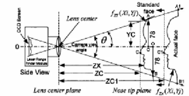
Size error from the camera occurs from digital capture of the object at various distances. Size error is solved by calculating the scale index, which is the relationship between the ratio of the frame size and the face size [14], the camera view angle, and the constant ratio of the standard distance, as described in Equations (8) through (13) in the next paragraph.
Figure 2. Range of variables for calculating scale index (Sy). As shown in Figure 2, scale index (Sy) is calculated from the relationship between size of face, distance and camera view angle, the relationship is as follows.
Since real size of face does not change in comparison with the distance (Fact), then, the actual face plane
)
,
(
Xi
Yj
ZAf
at ZC1 can be shifted to (Xi,Yj) ZSf
at ZC; therefore, the distance adjustment from actual nose tip to standard nose tip can be equally derived by Equation (8).) ZC ZC1 ( ) , ( ) , (XiYj = ZA XiYj − − ZS
f
f
(8) where (Xi,Yj) ZSf
is the RIFD plane at standard range (ZX),)
,
(
Xi
Yj
ZA
f
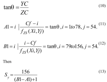
is the RIFD plane at actual range, i=1 to 156, j=1 to 108, ZC is the standard distance from the lens center plane to the nose tip plane (in this experiment ZC is assigned as 295 mm.), ZC1 is the distance from the lens center plane to the actual nose tip (Assuming that RIFD matrix size is 156×108 pixels).Image face size obtained from the camera is in inverse relation to distance and camera view angle (θ). Actual face size image from camera (changed by distance) is adjusted to real face size at the point of standard distance correctly, which calculates scale index of image (Sx, Sy, Sz) by using Equation (4).
Define: Sx and Sz =1 (Characteristic of Laser Range Finder Module)
2
156rows
ZC
YC
=
θ
tan
(10).
54
,
78
1
,
tan
)
,
(
1
=
−
=
i
=
to
j
=
Yj
Xi
f
i
Cf
i
A
ZSθ
(11).
54
,
156
79
,
tan
)
,
(
1
=
−
=
i
=
to
j
=
Yj
Xi
f
Cf
i
i
B
ZSθ
(12) Then1
)
1
1
(
156
+
−
=
A
B
S
y (13)where Cf is the center of frame, and Sx, Sy, Sz are scale index of X, Y, and Z-axis respectively. The character of Laser Range Finder Module (Strength module moving type) comprises laser scan and stereo cameras, which cooperatively work together. Further, Sx and Sz are independent with the distance; therefore, both are set to be equal to 1. However, Sy is changed following its distance of ZC1. The size of face range image can then be adjusted at any ZC1 to the ZC, to which is assigned the standard value. The Sy value can be found in Equation (13), which uses the scale index to correctly adjust the ratio of RIFD for each test subject. This Sy value is then inserted into Equation (4).
As mentioned, the RIFD is the referenced distance from the lens center plane to the face plane. For convenience of further calculation, the reference point is changed from the lens center plane to the nose tip plane for creating the RIFD to be instrument independent. The range image of an independent face surface plane
(
Xi
,
Yj
)
Z
f
is referred from the 65 mm nose tip and can be seen in the following Equation (14);)
,
(
)
(
)
,
(
Xi
Yj
ZC
ZD
ZSXi
Yj
Zf
f
=
+
−
(14)where ZD is the measured range downward from nose tip = 65 mm. (Standard constant), i = 1 to 156, j = 1 to 108. Therefore RIFD of each test subject will have the maximum value at the nose tip, which is equivalent to 65 mm. The result is shown in Figure 3.
Figure 3. Point C, center of rotation, is the nose tip having the position (XC,YC,ZC)
3.1.2 Centering
The nose tip position of the human face must be the defined position to the frame of RIFD, which is then transferred into the standard assigned position of the frame. This method is necessary due to its accuracy for data analysis. Center adjustment transferring is calculated by the following Equation (15-1) to (15-3). A C D
X
X
X
=
−
(15-1) A C DY
Y
Y
=
−
(15-2) A C DZ
Z
Z
=
−
(15-3) where XC, YC, ZC are nose tip positions, reference coordinates of frame at the position of 89, 54, 65 respectively. XA, YA, ZA are as actual nose tip position coordinates of input RIFD. And, the XD, YD, ZD assigned as displacement between the nose tip position coordinate and actual nose tip position coordinate. This value is then inserted into the matrix of Equation (5).3.2 Multi-poses generating
Multi-pose face recognition is the primary characteristic that is assigned for the condition of this experiment. Thus, it is necessary to generate a large quantity of pose position images for matching with the test face images. This method effectively uses the benefit of the range image data characteristic. RIFD poses are obtained from normalizing processes having the characteristics of Cartesian coordinates. This characteristic enables the transformation of the initial pose to the new pose position in the required region.
As seen in Figure 3, Point C (nose tip) is assigned as the center of the rotation. The RIFD is normalized and rotated using geometric transform in Equation (1). The initial pose face from one test subject is then regenerated into a series of 6 new pose images. The rotation is completed by the rotate range of ±6 degrees for LR by 2 degrees per pose. Figure 4 shows the face plane boundary of a rotated face within the region of ±24 degrees LR from initial pose (0, 0).
Figure 4. The region of face pose images that the system can acknowledge using multi-pose face ±24 degrees LR from initial pose. Display at 12 degree steps per pose.
3.3 Image Size Reduction [11]
The results from the experiment show the image size reduced by 4 times. The experimental results are still acceptable. Linear reduction is then used in lieu of the complex reduction approach in order to streamline the operation. Additionally, the size of the matrix is reduced to 78×54 pixels, as shown in Equation (16).
) 4 , 4 ( ) , (ij
=
Zi
i× j×Zo
(16) where Zi(x, y) is input Matrix, x=1 to 156, y=1 to 108, Zo(i, j) is output Matrix, i = 1 to 78, j =1 to 54. The result is shown in Figure 5 (c).(a) (b) (c) Figure 5. Range Image Data Reduction (a) Original with light source,
(b) 156×108 Original face range image, and (c) 78×54 reduction result.
4. RECOGNITION PROCEDURE 4.1 Fuzzy c-Means (FCM)
FCM is applied to the invariant range image multi-pose faces, which have similar features, make cluster and average vector. Each cluster can assign membership to the various data points in each fuzzy set. The steps of classification in this algorithm are as follows:
1. From RIFD database, we can define a family of fuzzy partition matrix, Mfc, for the classification involving c classes and n data points,
∈
=
<
<
=
∑
∑
= = ×n
U
M
n k ik c i ik ik o n c fc 1 1 ) (|
µ
[
0
,
1
];
µ
1
;
0
µ
(17) where i = 1, 2, …, c; k = 1,2, …, n andU
c(o×n)is a fuzzy c-partition (n data points, c classes) from the each pose of n face images. We fix c (2 ≤ c ≤ n) and initialize the U matrix:fc o
n
c
M
U
(×)∈
. Each step in this algorithm will be labeled r, where r = 1,2, ….
2. Create the data matrix in each pose,
X
n×z, so that it has z elements from each pose of n face images.3. Calculate the c center:
∑
∑
= ′ = ′⋅
=
n k m ik kj n k m ik ijX
V
1 1µ
µ
(18) where j = 1,2, …, mm’ is a weighting parameter to control the amount of fuzziness in the classification process.
4. Calculate dik: 2 / 1 2
)
(
)
(
−
=
−
=
k i∑
kj ij ikd
x
v
x
v
d
(19)where µik is the membership of the kth data point in the ith class.
5. Update the partition matrix for the rth step, U(r) as follows: 1 1 ) 1 /( 2 ) ( ) ( ) 1 ( − = − ′ +
=
∑
c j m r jk r ik r ikd
d
µ
for Ik = ∅ (20) or
µ
ik(r+1)=
0
for all classes I where I ∈I~
k (21) where Ik = { i | 2 ≤ c < n;d
ik(r) = 0} (22) and I~ = {1, 2, …., c} - Ik (23) k and∑
( 1)=
1
∈ + k I i r ikµ
(24)6. If || U(r+1) – U(r) || ≤ εL, stop; otherwise set r = r+1 and return to step 3.
4.2 The steps of matching search
The matching search is used to search the pose position for matching a pose of maximum similarity. By using this technique, it can then access the best similar pose position in the multi-pose database. The steps of the matching search in this algorithm are as follows.
1. Add the test data (the unknown face) into the row in the database matrix
X
n×z. So, the database matrix changes to the test data matrixX
(n+ )1×z.2. Create the matrix
U
c(×o()n+1), by adding the (n+1)th column to the matrixU
c(o×)n, where the value of the first row in the last ((n+1)th) column equals 1, and the values of the other rows in the (n+1)th column are equal 0.3. Calculate the c center as in equation (18), where j = 1, 2, …, n+1.
4. Calculate dik as similar in equation (19).
5. Update partition matrix U(r) for the rth step. Consider
µ
ik(r+1) in equation (20) following to the condition in equation (21), and the position Ik following the condition in equation (22).6. If || U(r+1) – U(r) || ≤ εL, stop (εL = 0.006); otherwise set r = r+1 and return to step 3.
7. Select the biggest membership values in the (n+1)th column (unknown face image).
8. Consider the biggest membership values in each column from the first column to the nth column (face image database).
9. Calculate the fuzzy relationship of the biggest membership values between a face image database and an unknown face image.
10. Select the least fuzzy relationship sent to the graphic user interface to identify the unknown face image.
5. EXPERIMENTAL AND RESULTS 5.1. Selected data type for the experiment
During the image processing session, image acquisition, feature extraction, generating multi-pose face images and normalization are performed. In the next step, a method to determine the fuzzy c-partition matrix U(o) for grouping a collection of n data sets into c classes. The criteria of head variations and facial pose that adopted in this study are as follows:
1. Normal pose, 2. Browse left 6°, 3. Browse right 6°.
Then, we have a new pose 6 new pose images for left/right (2 degrees per pose) add into the RIFD database for classification by the algorithm in section 4.1.
5.2. Multi-pose face recognition test
In the testing step, we use the algorithm of the matching search in section 4.2 to identify a person with the RIFD database.
The multi-pose face recognition test wholly aims to find the rate of systematic recognition, which determines the rate recognition of the test face with the region of view poses ±6ºLR from the initial pose. The assigned condition in this experiment provides that the system must recognize the test face, even if the pose changes. However, in the experiment, it was found to be difficult to input acquisition RIFD following the viewpoint angle because of the many variables presented, such as distance, center, inclination, and stoop of face. Furthermore, input acquisition RIFD was even more difficult to do covering all regions, ±6ºLR for each pose. Fortunately, a 3-D base of the RIFD can accurately imitate the test face at different pose angles.
In the experiment, the face images of 40 persons were scanned 3 times. The first two sets of data were stored as a reference data, the third one is used as a testing data. For critical control, we scanned human face, which showed normal emotion. The experiment results have been 92.86 % accurate. Improvements to the one part of this security system would increase security benefits and tracking of known felons.
6. CONCLUSIONS
The face recognition system, which employs the ±6 degrees left/right face images from 40 people in the recognition process, has been proven to be highly successful. This research used the integration of fuzzy c-means into the classification technique of the invariant range image multi-pose face recognition process. The experiment confirms that fuzzy c-means is better than k-means for classifying the face surface. Table 1 shows the comparison of recognition results. In each method, we can see the percentage of recognition for which the best result was fuzzy c-means. The percentage of the second result was k-means and matching approaches [12] respectively.
In the future, we plan on adding more subjects and more multi-pose images into the database. The face recognition system in the security system is a wide area of application to be applied especially in high security situations such as automatic teller machines, security rooms, automatic safes and confidential information access facilities.
Table 1. Show the comparison of Recognition rates. Recognition Methods Recognition rates (%) Matching approaches [12] 85.00
K-means 85.71
Fuzzy c-means 92.86
REFERENCES
[1] K. Bowyer, K. Chang, P. Flynn, “A Survey of Approaches to 3D and Multi-Modal 3D+2D Face Recognition”, IEEE International Conference on Pattern Recognition Cambridge, United Kingdom. Aug. 2004. [2] W. Zhao, R. Chellapa, and A. Rosenfeld, “Face
recognition: a literature survey”, ACM Computing Surveys, vol.35, pp.399-458, Dec. 2003.
[3] R. Chellappa, C. Wilson, and S. Sirohey, “Human and machine recognition of faces: A survey”. Proc.IEEE, vol.83, no.5, pp.705–740, 1995.
[4] W. Y. Zhao, R. Chellappa, A. Rosenfeld, P. J. Phillips, “Face Recognition: A Literature Survey”, UMD CfAR Technical Report CAR-TR-948, 2000.
[5] T.J. Ross, Fuzzy Logic With Engineering Applications pp. 388-396, McGraw-Hill, Inc., 1995.
[6] G.G. Gordon, “Face recognition based on depth maps and surface curvature”, SPIE Geometric methods in Computer Vision, San Diego, vol. 1570, 1991.
[7] G. G. Gordon, “Face Recognition Based on Depth and Curvature Feature”, Proc. IEEE CVPR’92, pp.808-810, June 1992.
[8] S.D Chang, M. Rioux, J. Domey, “Face Recognition with Range Images and Intensity Images”, Opt. Eng., vol.36, no.4, pp. 1106-1112, April 1997.
[9] S.C. KEE, K.M. LEE, S.U. LEE, “Illumination Invariant Face Recognition Using Photometric Stereo” IEICE Trans. Inf. & Syst., Vol.E83-D, no.7, pp.1466 – 1474, July 2000.
[10] R. Koch, M.H. Groß, “Analysis and segmentation of facial features in laser range data”, Proc. International Workshop on Automatic Face and Gesture-Recognition., pp. 362-367, Switzerland, June 1995.
[11] S. pansang, B. Attachoo, C. Kimpan and M. Sato, “Invariant Range Image Multi-pose Face Recognition Using Gradient Face, Membership Matching Score and 3-Layer Matching Search”, IEICE Trans. Inf. & Syst., vol.E88-D, no. 2 pp.268-27, Feb. 2005.
[12] S. Pansang, B. Attachoo, C. Kimpan, and P. Phokharatkul. “Range Image Invariant Face Recognition using Wavelet Transform”, Proc. SCI’2003, pp.156-160, July, 2003.
[13] R.C. Gonzalez, Digital image processing. pp. 36-40, Addison-Wesley Publishing Company, 1987.
[14] C. Beumier, M. Acheroy, “Automatic Face Verification from 3D and Grey Level Clues”, Proc. RECPAD2000, 11th Portuguese conf. on patt. Recog., pp. 95-101, Porto, Portugal, May 2000.