680
-Abstract– This paper proposes a comparative study of dual-airgap flux switching permanent magnet (FSPM) and spoke-type interior permanent magnet (S-IPM) machines equipped with phase-group concentrated-coil (PGCC) windings. Both of the investigated machines are the same size and material amounts which are compared at the same operating conditions. All the relevant machine performance including back electromotive force (EMF), cogging torque, and electromagnetic torque are analyzed by a 2-D time-stepping finite element method (FEM).1. Introduction
Permanent magnet (PM) machines have been applied in many applications due to their significant advantages such as high torque/power density and high efficiency [1]-[2], primarily as a result of the advancement of high-energy rare earth magnets. Based on the location of PMs, the PM machines can be briefly classified into rotor-PM machines and stator-PM machines. In general, the rotor-PM machines including the surface-mounted, surface inset, and interior types predominate in current domestic and industrial applications due to their well-known advantageous attributes. Recently, stator-PM machines especially flux switching PM (FSPM) machines, have re-emerged with increasing research interests aiming at overcoming some of the problems suffered from rotor-PM machines [3]. However, a common challenge for both kinds of PM machines exists from the viewpoint of production cost since the raw materials of rare earth PMs have the problem of high price and limited supply. Furthermore, PM machines, in particular fractional slot PM machines and FSPM machines, heavily researched recently, are often equipped with concentrated windings offering the advantage of short end turns for reduced winding cost, weight, and loss, but suffer a low effective winding factor. Hence, research and development of high performance machines with less or no rare earth magnets is now of great importance.
In [4] and [5], an advanced design mechanism for the flux switching permanent magnet (FSPM) and spoke-type interior permanent magnet (S-IPM) machines, in which the phase-group concentrated-coil windings and unaligned arrangement of two rotors/stators are utilized, has been proposed for the improvement of performance such as torque/power density, efficiency, cogging torque, and torque ripple, respectively. In this paper, a comparative study between the dual-airgap FSPM and S-IPM machines conformed to the design mechanism is performed to provide insights into their performance differences. Both of the investigated machines are the same size and material amounts. ll the relevant machine performance including back electromotive force (EMF), cogging torque, and electromagnetic torque are analyzed by a 2-D time-stepping finite element method (FEM) at the same operating conditions.
2. Machine Modeling
The topologies of the investigated machines are shown in Fig. 1. The dual-rotor FSPM machine with 24 stator slots (S) and 25 rotor poles (P) with PGCC windings is shown in Fig. 1(a), and the dual-stator S-IPM machine with 24 stator slots (S) and 26 magnet poles (P) is shown in Fig. 1(b). Both of the two machines have the same specifications as listed in Table I.
<Fig. 1> Topologies of the investigated machines. (a) FSPM machine; (b) S-IPM machine.
<Table I> Specifications of the investigated Machines
<Fig. 2> Design concepts of the investigated machines (developed view). (a) FSPM machine; (b) S-IPM machine.
Both machines are designed as conformed to the design concept in Fig. 2 (a) for the FSPM machine, and Fig. 2 (b) for the spoke-type IPM machine as in [4] and [5], respectively. Therefore, almost the total PM flux corresponding to one phase group (i.e. the area in the red dotted line box) will follow into one airgap when the rotor pole rotates to become aligned with the teeth of stator. After π/2 (elec.) rotation, the same effects will occur in the other airgap. Thus, a highly improved airgap flux density resulting in a higher resultant torque can be obtained than the conventional dual airgap machines in which two air gaps work independently.
상 그룹 집중권 권선을 갖는 2중 공극 플럭스 스위칭기기와 스포크타입 매입형 영구자석 기기의 비교 연구
조문량, 권병일 한양대학교 전자시스템공학과
Comparative Study of Dual-airgap Flux Switching and Spoke-type Interior Permanent Magnet
Machines with Phase-group Concentrated-coil Windings
Wenliang Zhao, Byung-il Kwon
Hanyang University, Electronic Systems Engineering
Item Unit FSPMM S-IPMM Machine outer diameter mm 264
Machine axial length mm 96 Airgap length mm 1.0 / 0.8 Coil turns per phase - 160
Machine weight kg 20.2 19.7
Material cost $ 53 47
681
-3. FEM Analysis ResultsThe performance of the investigated machines are compared based on 2-D finite element method (FEM). Fig. 3 shows the comparison of magnetic flux density distribution at no-load case. It shows that almost all the PM flux in both machines is focused into one airgap corresponding to one phase group (i.e. the area in the red dotted line box). Fig. 4 shows the comparison of the phase back EMFs and Fig. 5 shows the corresponding fast Fourier transform (FFT) analysis, which indicate the FSPM machine has higher fundamental components than the S-IPM machine due to the magnetic gearing effects as demonstrated in [6].
<Fig. 3> Magnetic flux density distribution. (a) FSPM machine; (b) S-IPM machine.
<Fig. 4> Comparison of back EMFs.
<Fig. 5> FFT analysis of back EMFs.
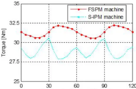
Fig. 6 shows the comparison of cogging torques and Fig. 7 shows the comparison of electromagnetic torques at the current density of 5 Arms/mm2, which show the FSPM machine has higher average
torque (+8.6%), and lower cogging torque (-16.9%) and torque ripple (-69.1%). However, the FSPM machine exhibit much higher iron loss due to the higher electric frequency, thus resulting in much lower efficiency (-7.3%) than the S-IPM machine, while the loss and efficiency are predicted as in [6]. The results are listed in Table II.
<Fig. 6> Comparison of cogging torques.
<Fig. 7> Comparison of electromagnetic torques. <Table II> 2-D FEM Analysis Results
4. Conclusion
This paper has carried out a comparative study of the dual-airgap FSPM and S-IPM machines with phase-group concentrated-coil windings. Based on the FEM analysis results, it was found that the FSPM machine has higher average torque (+8.6%), and lower cogging torque (-16.9%) and torque ripple (-69.1%), but lower efficiency (-7.3%) than the S-IPM machine. Thus, although both machines with the advanced design mechanism can obtain high performance judging from the previous research, the FSPM machine is more attactive for high-torque applications, while the S-IPM machine is appreciated in high-efficiency applications.
This research was supported by the Human Resources Program in Energy Technology of the Korea Institute of Energy Technology Evaluation and Planning (KETEP), granted financial resource from the Ministry of Trade, Industry and Energy, Republic of Korea (20154030200730).
[References]
[1] M. J. Melfi, S. D. Rogers, S. Evon, and B. Martin, “Permanent-magnet motors for energy savings in industrial applications,” IEEE Trans. Ind. Appl., vol. 44, no. 5, pp. 1360– 1366, Sep./Oct. 2008.
[2] K. T. Chau, C. C. Chan, and C. Liu, “Overview of permanent-magnet brushless drives for electric and hybrid electric vehicles,” IEEE Trans. Ind. Electron., vol. 55, no. 6, pp. 2246– 2257, Jun. 2008.
[3] M. Cheng, W. Hua, J. Zhang, and W. Zhao, “Overview of stator permanent magnet brushless machines,” IEEE Trans. Ind. Electron., vol. 85, no. 11, pp. 5087–5101, Nov. 2011.
[4] W. Zhao, T. A. Lipo, and B. I. Kwon, “Design and analysis of novel dual rotor axial field flux switching permanent magnet machines," Annual autumn conference of KIEE, Oct. 2014. [5] W. Zhao, T. A. Lipo, and B. I. Kwon, “Comparative study on
novel dual stator radial flux and axial flux permanent magnet motors with ferrite magnets for traction application,” IEEE Trans. Magn., vol. 50, no. 11, Nov. 2014.
[6] Z. Z Wu, and Z. Z. Zhu, “Analysis of air-gap field modulation and magnetic gearing effects in switched flux permanent magnet machines," IEEE Trans. Magn., in press.
Item Unit FSPMM S-IPMM Electric frequency Hz 187.5 97.5 Back EMF V 49.55 44.98 Cogging torque Nm 1.72 2.07 Average torque Nm 31.4 28.9 Torque ripple % 5.41 9.15 Power @450rpm W 1480 1362 Torque density Nm/kg 1.55 1.47 Power density W/kg 73.25 69.13 Copper loss W 127.05 125.96 Iron loss W 166.84 25.1 Efficiency % 83.43 90.02