2196
Copyrightⓒ The Korean Institute of Electrical Engineers
Development of Protection Method for Power System interconnected
with Distributed Generation using Distance Relay
Ji-Soo Kim*, Gyu-Jung Cho*, Jin-Sol Song*, Jae-Yun Shin*, Dong-Hyun Kim*
and Chul-Hwan Kim
†Abstract– The conventional power system allowed only downstream power flow. Therefore, even if
a fault occurs, only the forward current flow is considered. However, with the interest in distributed generation (DG), DGs such as Photovoltaic (PV), Wind Turbine (WT) are being connected to a power system. DGs have many advantages, but they also have disadvantage such as generation of reverse flow. Reverse flow can severely disrupt existing protection systems that only consider downstream power flow. The major problems that may arise from reverse power flow are blinding protection and sympathetic tripping. In order to solve such problems, the methods of installing a directional relay or a fault current limiter is proposed. However, this method is inconceivable because of the economics shortage. Therefore, in this paper, a distance relay installed in existing power system is used to solve the protection problem. Modeling of distance relay has been carried out using ElectroMagnetic Transients Program (EMTP), and it has been verified through simulations that the above problems can be solved by a distance relay.
Keywords: Blinding protection, Distance relay, Distributed generation, Sympathetic tripping,
protection
1. Introduction
Due to various problems such as the environmental problems of the existing energy sources, the capacity of the distributed generation (DG) connected to the power system is increasing. DGs have the advantage of clean energy and can solve the problems of existing energy sources. However, also DGs have various problems as they are connected to the grid. One of them is a protection problem. Since the existing power system is a radial system, the power flow only in the downstream direction is considered, so that the protection system of grid only take account of uni-direction. However, the direction of these power flow changes variously due to the connection of the DGs [1-2].
As the DGs are connected to the middle or end of the feeder, the reverse power flow is generated and the nuisance tripping of circuit breaker is occurred due to the fault in neighbor feeder. In addition, when a fault occurs, the fault contribution of the main power source is reduced because of the fault contribution of DG and circuit breaker can fail to detect the fault. Each of these problems is called sympathetic tripping and blinding protection. Problems such as sympathetic tripping can be solved by installing directional relays or fault current limiter, and blinding
protection can be solved through the coordination of existing overcurrent relays. However, this approach causes economic costs and therefore it is not realistic [3-5].
Therefore, in this paper, we propose a solution to solve the problem of blinding protection and sympathetic tripping using the distance relay and verify the algorithm with ElectroMagnetic Transients Program (EMTP).
2. Principle of Distance Relay Operation
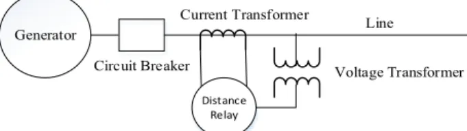
As the name implies, the distance relay measures the distance from the relay installation location to the fault location and trip the circuit breaker to clear fault in protection zone. The distance relay receives the voltage and current of the installation location of relay and calculates the impedance of the line to estimate the fault location. Therefore, the connection shown in Fig. 1 is formed [6].
Generally, the turn ratio of current transformer and voltage transformer is 1:1 when a distance relay is installed. In this way, the distance relay receives the voltage and
† Corresponding Author: College of Information and Communication Engineering, Sungkyunkwan University, Korea.
(hmwkim@ hanmail.net)
* College of Information and Communication Engineering, Sung-kyunkwan University, Korea. ({kjs7107, thug1220, wlsthf6, sjy784, kdhslass}@naver.com)
Received: June 14, 2018; Accepted: June 27, 2018
Generator Distance Relay Line Current Transformer Voltage Transformer Circuit Breaker
current in complex form, and is expressed by (1) and (2) [7-8]. 2 2 1 X Y X Y V V= + jV = V +V Ðq (1) 2 2 2 X Y X Y I=I +jI = I + ÐI q (2)
Where, V = Real component of voltageX
Y
V = Imaginary component of voltage X
I = Real component of current Y
I = Imaginary component of current
1
q = Phase of voltage 2
q = Phase of current
Therefore, the measured impedance Z is as follows.
2 2 1 2 2 2 ( ) X Y X Y V V V Z I I I q q + = = Ð -+ (3)
In this case, if the magnitude of the voltage and the current are kept constant regardless of the phase, the magnitude of the impedance becomes constant. Therefore, the trajectory of the impedance on the R-X diagram varies only in phase, so that the circle is shown in Fig 2. And the magnitude of the line impedance corresponding to the protection area of the distance relay becomes the criterion for determining the trip area. If a fault occurs, the fault current increases and the voltage decreases, so that Z in (3) becomes smaller. If Z belongs to the trip area, it is judged as a fault condition and the relay trips through the breaker. In general, a distance relay installed in a line moves the trip area through a series connection with a directional relay, and searches for a fault only in one direction. However, in this paper, the area shown in Fig. 2 is maintained in order to prevent sympathetic tripping [7-8].
Also the distance relays usually have impedance elements and an inverse-time relay in three stage, with 85%, 150%, and 230% time delays. Zone 1 is 85% of the protection zone, and the trip is instantaneous. Zone 2 is 120% of the protection zone. The timer is used to operate when the
other circuit breaker is disabled, and has a delay operation of about 20Hz. Finally, Zone 3 has delay of about 100Hz with 230% of protection [8].
3. Blinding Protection and Sympathetic Tripping
3.1 Blinding protection
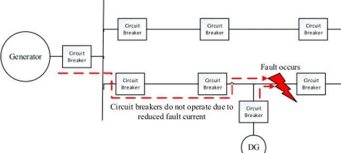
Blinding protection is a phenomenon that occurred due to reduction of the fault contribution of the main power source because fault contribution of DG is increasing. That is, when the DG is not installed, the circuit breaker that can be tripped through the overcurrent relay after the fault occurs does not trip because the fault contribution of main power source is reduced. This situation can be easily seen from Fig. 3 [9].
Therefore, in order to solve the blinding protection, it is necessary to correct the pickup current setting value of the overcurrent relay. However, this correction process have to be repeated every time an additional DG is installed. In addition, the optimization process must be essential and cost problems arise.
3.2 Sympathetic tripping
Sympathetic tripping refers to the phenomenon that a circuit breaker malfunctions if other feeders including the feeder in fault are considered to be fault situation. Blinding protection can be solved by changing the pickup current setting value of the overcurrent relay, but the solution of sympathetic tripping is more complex. Fig. 4 shows an
Fig. 2. Trip area of distance relay
Generator BreakerCircuit
Circuit
Breaker BreakerCircuit BreakerCircuit
Circuit
Breaker BreakerCircuit BreakerCircuit Circuit
Breaker
DG Fault occurs
Circuit breakers do not operate due to reduced fault current
Fig. 3. Example of blinding protection
Generator Circuit Breaker
Circuit
Breaker BreakerCircuit BreakerCircuit
Circuit
Breaker BreakerCircuit BreakerCircuit Circuit
Breaker
DG Fault occurs
Trip of circuit breaker caused by overcurrent in a line without fault
example of the sympathetic tripping [9].
Therefore, due to the operation of the circuit breaker in healthy feeder which should not occur as shown in Fig. 4, the line with no fault will also be in a blackout state. A typical method to prevent sympathetic tripping is to install a directional relay or a fault current limiter. The first way is to install a directional relay and not trip the overcurrent in the reverse direction. If the line in fault is disconnected by using this method, the line that has not been faulted becomes normal condition. A second method of installing a fault current limiter is to limit the magnitude of the fault current output from the DG so that the overcurrent relay is not tripped. However, these methods of installing the directional relay or fault current limiter are not economical because all directional relays have to be connected in series to all overcurrent relays and the fault current limiter must be connected to all DGs.
4. Proposed Method using the Distance Relay
In this paper, we choose a method of utilizing the distance relay as main protection for power system with DG, not an overcurrent relay. As described in Section 3, the blinding protection and sympathetic tripping can be solved by adjusting the setting value of overcurrent relay, and by installing the directional relay. These two methods can be solved at once by using the distance relay with proposed method. By adjusting the trip area of in Fig. 2, blinding protection can be solved and sympathetic tripping can be solved by using the function to determine the direction of the distance relay.
4.1 Countermeasure of blinding protection
There is a characteristic that the fault current is larger as the relay is closer to the location where the fault occurs. If the distance between relay and fault location is closer, the fault current is larger and then voltage is being lower. Therefore, Z in (3) becomes much smaller. The smaller the value of Z included the trip area, the faster the disconnection speed and the circuit breaker close to the fault location opens. This principle of the distance relay is more sensitive because it judges both voltage and current differently from the method of only measuring current in the overcurrent relay. As a result, it is a solution to solve the blinding protection problem by using the distance relay as the main protection.
4.2 Countermeasure of sympathetic tripping
In the case of sympathetic tripping, reverse power flow due to the other feeder is a main problem of protection. Therefore, if the reverse power flow is generated after a fault, the circuit breaker should not operate. In detail, when the power flows in the forward direction, if reverse power
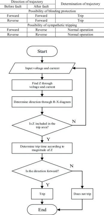
occurs after fault situation, circuit breaker does not have to be tripped. On the other hand, if Z is in the reverse zone in trip area when fault occurs during the existing reverse power flow through relay, it does not trip even this time. Therefore, the methods in Section 4.1 and Section 4.2 can be summarized in Table 1.
Finally, the algorithm of the relay is configured as shown in Fig. 5.
Therefore, if Z by using our proposed method is in the reverse direction, the distance relay does not trip considering the sympathetic tripping phenomenon. And if it is in the
Table 1. Determination of trip according to direction of
flow
Direction of trajectory
Before fault After fault Determination of trajectory Possibility of blinding protection
Forward Forward Trip
Reverse Forward Trip
Possibility of sympathetic tripping
Forward Reverse Normal operation Reverse Reverse Normal operation
Input voltage and current
Find Z through voltage and current
Determine direction through R-X diagram
Is Z included in the trip area?
Is the direction forward?
Trip Does not trip
End Start Y Y N N
Determine trip time according to magnitude of Z
forward direction, it should be tripped considering blinding protection.
5. Simulation Conditions and Results
5.1 Simulation conditions
In this simulation, we assume a 154kV transmission system with two feeders shown as Fig. 6. There are two fault locations, one on the feeder with no DG connected and the other on the end of the feeder with DG connected.
In the fault location 1, it is verified that the distance relay prevented the sympathetic tripping, and in the fault location 2, the distance relay effectively prevents the blinding protection. The total simulation time is 1 second and the three phase fault occurs in 0.5 seconds. In addition, DG is connected to the grid in 0.1 seconds.
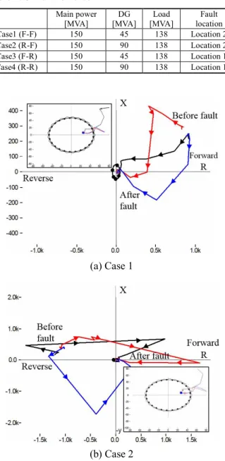
Also, for the verification of the algorithm in Section 4, 4 cases are assumed considering in Table 2. And the capacity is selected as shown in Table 2. ‘F’ and ‘R’ denote forward and reverse direction of the power flow.
5.2 Simulation results and analysis
Fig. 7 shows the blinding protection situation. In the absence of DG, the fault current rises to 2.7kA, however the fault current from main power source is decreasing to
Distance Relay Load 345/154[kV] Fault location 1 Fault location 2 DG
Load Load Load
Circuit Breaker Circuit
Breaker Load Load
Fig. 6. Simulation system
(a) Case 1
(b) Case 2
Fig. 7. Comparison of main power source’s fault
con-tribution
Table 2. Simulation case
Main power [MVA] DG [MVA] Load [MVA] Fault location Case1 (F-F) 150 45 138 Location 2 Case2 (R-F) 150 90 138 Location 2 Case3 (F-R) 150 45 138 Location 1 Case4 (R-R) 150 90 138 Location 1 (a) Case 1 (b) Case 2
2.5kA in case 1 and 2.3kA in case 2. This results indicate that if the pickup current setting value of the overcurrent relay is 2.5kA, the circuit breaker is not tripped and system is maintained in a fault situation. Also, as the capacity of DG increases, the fault contribution of the main power source becomes smaller. Therefore, in the future, as the penetration of the DG increases, it is expected that there will be a huge reduction for the fault contribution of the main power source. As a result, the overcurrent relay can be difficult to detect the fault current.
However, the proposed algorithm succeed to detect fault. Fig. 8 shows the trajectory of Z in the R-X diagram in the case 1 and 2. It can be seen that the trajectory of Z is accurately drew in the direction of power flow. Also, it can be seen that Z goes into the zone according to the existing protection zone of distance relay in forward direction. Therefore, circuit breaker should be tripped regardless of main power source’s fault contribution reduction.
In case of 3 and 4, Fig. 9 shows the fault current from the DG. Each case of 3 and 4, highest current is 1.4kA and 2.1kA. As a result, it can be seen that as the capacity of the DG increases, the contribution of the fault current is higher. Such a high overcurrent can cause a malfunction of the relay.
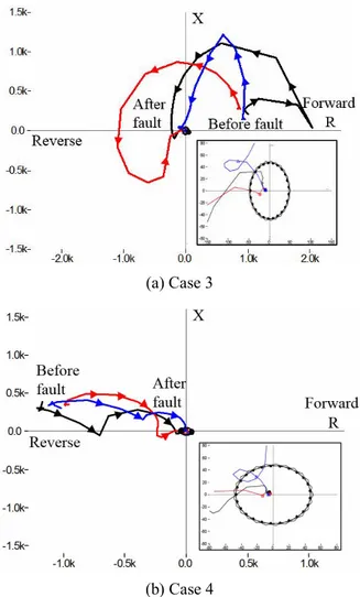
Also, as in Fig. 8, the trajectory of Z corresponding to case 3 and 4 is are shown in the R-X diagram as Fig. 10. Unlike the blinding protection, we can see that the trajectory of Z goes into the reverse direction. Therefore, in these cases, the circuit breaker is not tripped in bottom line because Z has changed to the reverse direction immediately after the fault occurred. Therefore, unlike the protection system using the existing overcurrent relay, there is no occurrence of the outage in bottom line.
As can be seen from the results, the algorithm using the distance relay can solve the blinding protection and sympathetic tripping that could not be solved by the existing protection system coordination. However, there is a drawback in that it is necessary to modify the protection coordination of the distance relay, which only considers the conventional uni-direction power flow, while adding the directionality to the distance relay. Even so, it is expected that this method will be useful in the meshed or loop system. Also if proper coordination is established in the radial system, it is possible to solve various problems that may arise in the system which connected with DG even if there is no additional directional relay or fault current limiter.
6. Conclusion
In this paper, we propose the method to solve the protection problems that can occur in the grid when the DGs are connected using the distance relay. The problems of blinding protection and sympathetic tripping can be solved by using trip area and directional component of the
distance relay. As the results, it can be concluded that the failing protection using the overcurrent relay are overcome by using distance relay with our proposed method. However, in order to use the distance relay as the main protection, the novel coordination between the distance relays should also be considered. If this study is completed by future studies, it can be used also in the meshed and loop system.
Fig. 9. Fault current from DG of case 3 and 4
(a) Case 3
(b) Case 4
Acknowledgements
This work was supported by the National Research Foundation of Korea(NRF) grant funded by the Korea government(MSIP) (No. 2015R1A2A1A10052459).
References
[1] Hadi Khani, Nader El-Taweel and Hany E.Z. Farag, “Real-time optimal management of reverse power flow in integrated power and gas distribution grids under large renewable power penetration,” IET Generation, Transmission and Distribution, vol.12, no. 10, pp. 2325-2331, May. 2018.
[2] Kallisthenis I. Sgouras, Aggelos S. Bouhouras, Paschalis A. Gkaidatzis, Dimitrios I. Doukas and Dimitris P. Labridis, “Impact of reverse power flow on the optimal distributed generation placement problem,” IET Generation, Transmission and Distri-bution, vol. 11, no. 18, pp. 4626-4632, Dec. 2017. [3] Bishnu P. Bhattarai, Birgtte Bak-Jensen, Sanjay
Chaudhary and Jayakrishnan R. Pillai, “An adaptive overcurrent protection in smart distribution grid,” in Proceedings of IEEE PowerTech 2015 Conference, Eindhoven, Netherlands, June 2015.
[4] Niraj Kumar Choudhary, Soumya Ranjan Mohanty and Ravindra Kumar Singh, “Protection coordination of over current relays in distribution system with DG and superconducting fault current limiter,” in Proceedings of 2014 Eighteenth National Power Systems Conference, Guwahati, India, May 2015. [5] Jakub Ehrenberger and Jan Svec, “Directional
over-current relays coordination problems in distributed generation systems,” Energies, vol. 10, no. 10, pp. 1-17, Oct. 2017.
[6] Sadegh Vejdan, Majid Sanaye-Pasand and Tarlochan S. Sidhu, “Accelerated zone II operation of distance relay using impedance change directions,” IEEE Transactions on Power Delivery, vol. 32, no. 6, pp. 2462-2471, Dec. 2016.
[7] Indrajeet Bhavar, Snehal Unde and Sanjay Dambhare, “Adaptive distance relaying scheme with fault resistance compensation,” in Proceedings of IEEE Region 10 Coneference, Marina Bay Sands, Singapore, Nov 2016.
[8] G. J. Cho, K. S. Ryu, H. D. Lee, S. H. Heo, H. D. Kim, C. H. Kim and S. I. Kwon, “A study on the distance relay operation characteristics for Korean single track AC electrical railway system,” in Pro-ceedings of Development in Power System Protection 2016, Edinburgh, UK, Mar 2016.
[9] Edward Coster, Johanna Myrzik and Wil Kling, “Effect of DG on distribution grid protection,” INTECH Open Access Publisher, Feb. 2010.
Ji-Soo Kim He was born in Korea, in
1992. He received a B.S degree from the College of Information and Com-munication Engineering, Sungkyunkwan University, Republic of Korea, in 2016. At present, he is enrolled in the com-bined master’s and doctorate program. His research interests include power system transients, wind power generation and distributed energy resource.
Gyu-Jung Cho He was born in Korea
in 1986. He received a B.S and M.S. degree from the College of Information and Communication Engineering, Sungkyunkwan University, Republic of Korea, in 2012 and 2014. At present, he is working on his Ph.D. thesis. His research interests include power system transients, protection and power system relaying.
Jin-Sol Song He was born in Korea, in
1993. He received a B.S degree from the College of Information and Com-munication Engineering, Sungkyunkwan University, Republic of Korea, in 2017. At present, he is enrolled in the com-bined master’s and doctorate program. His research interests include power system transients, wind power generation and distributed energy resource.
Jae-Yun Shin He was born in Korea,
in 1993. He received a B.S degree from the College of Information and Com-munication Engineering, Sungkyunkwan University, Republic of Korea, in 2017. At present, he is going through master’s course. His research interest include system voltage regulation and distributed energy resource.
Dong-Hyun Kim He was born in
Korea, in 1991. He received a B.S degree from the College of Con-vergence Technology, Korea National University of Transportation, Republic of Korea, in 2017. At present, he is going through master’s course. His research interest include protection of lightning problem and distributed energy resource.
Chul-Hwan Kim He was born in
Korea, in 1961. He received a B.S., M.S., and Ph.D. degrees in electrical engineering from Sungkyunkwan Uni-versity, Suwon, Korea, in 1982, 1984, and 1990, respectively. In 1990, he joined Cheju National University, Cheju, Korea, as a Full-Time Lecturer. He was a Visiting Academic with the University of Bath, Bath, U.K., in 1996, 1998, and 1999. He has been a Pro-fessor with the College of Information and Communication Engineering, Sungkyunkwan University, since 1992, where he is currently the Director of the Center for Power Information Technology. His current research interests include power system protection, artificial intelligence applications for protection and control, modeling/protection of underground cable, and electromagnetic transients program software.