ICCAS2005 June 2-5, KINTEX, Gyeonggi-Do, Korea
Optimal Fuzzy Control of Parallel Hybrid Electric Vehicles
M. Farrokhi, and M. MohebbiFaculty of Electrical Engineering, Iran University of Science and Technology (Tel: +98-21-780-8022; Fax: +98-21-7454055)
(Email: [email protected], [email protected])
Abstract: In this paper an optimal method based on fuzzy logic for controlling parallel hybrid electric vehicles is presented. In parallel hybrid electric vehicles the required torque for deriving and operating the on-board accessories is generated by a combination of internal-combustion engine and an electric motor. The power sharing between the internal combustion engine and the electric motor is the key point for efficient driving. This is a highly nonlinear and time varying plant and its control strategy will be implemented with the use of fuzzy logic controller. The fuzzy logic controller will be designed based on the state of charge of batteries and the desired torque for driving. The output of controller controls the throttle of the combustion engine. The main contribution of this paper is the development of an optimal control based on fuzzy logic, which maximizes the output torque of the vehicle while minimizing fuel consumed by the combustion engine.
Keywords: Hybrid electric vehicles, Fuzzy logic, Optimal Control, State of charge
1. Introduction
During the last two decades of the 20th Century, as it is well
known, global concerns to reduce emissions and improve fuel efficiency have been steadily increasing.
Environmental as well as economical issues provide a compelling impetus to develop clean, efficient and sustainable vehicles for urban transportation. Automobiles constitute an integral part of our everyday life, yet the exhaust emissions of conventional Internal Combustion Engine (ICE) vehicles are to blame for the major source of urban pollution that causes the greenhouse effect leading to global warming. The dependence on oil as the sole source of energy for passenger vehicles has economical and political implications, and the crisis will inevitably become acute as the oil reserve of the world diminishes. The number of automobiles on our planet doubled to about a billion or so in the last 10 years. The increasing number of automobiles being introduced on the road every year is only adding to the pollution problem. There is also an economic factor inherent in the poor energy conversion efficiency of combustion engines [1].
Until 19th Century, above all, Electric Vehicles (EVs) that
have no emissions have stood in the spotlight all over the world. However, as pure electric vehicles have some drawbacks, such as a short driving distance, long recharging time and high costs, in the 1990s a large number of auto industries started developing Hybrid Electric Vehicles (HEVs) to overcome the problems of pure electric vehicles. The HEV seems to be the viable alternative to the ICE and electric automobiles at the present.
HEVs can be broadly classified as series or parallel hybrid systems. In series HEVs, same as EVs, all the torque required to propel the vehicle is provided by an electric motor, but in parallel HEVs, the torque obtained from the heat engine is mechanically coupled to the torque produced by an electric motor [2].
2. System Model Description
2.1 Parallel Hybrid Electric Vehicle Architecture
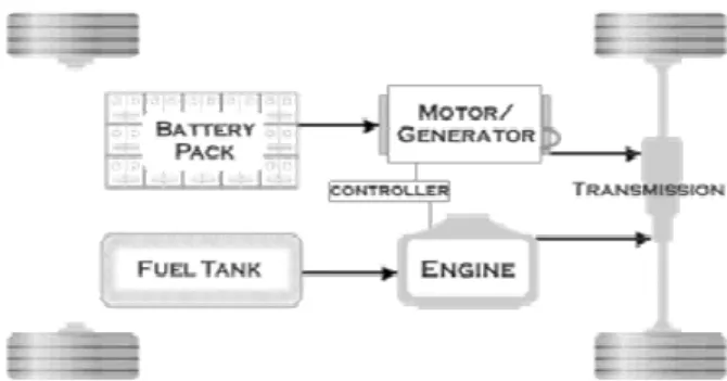
Fig. 1, that obtained from [3], presents the block diagram of a parallel HEV powertrain with an electrical machine and an ICE that they are combined together to propel the vehicle. The electrical machine works as generator when the state of charge (SOC) of batteries is low and is needed to charge the batteries, and works as motor when its torque is needed for driving the vehicle. The controller that will be designed by fuzzy logic method, controls the engine by changing its throttle angle in each time in order to control its produced torque to reach our control goals. Then the desired torque of electric motor will be measured by subtracting the real engine output torque, from the desired torque in any times.
Fig. 1. The block diagram of a parallel HEV powertrain 2.2 Engine Dynamic Model
We use a simple model of engine that Xiao Yun Lu introduced in [4]. His model includes a two states dynamic model with the output of engine produced torque. The states include the speed of engine (N) as x1 and the manifold pressure (Pm) as x2. Lu’s model is presented in the following Eqs: load T x x x x x x x x 1429 . 7 00076429 . 0 24428 . 0 91185 . 0 29 . 307 77 . 818 3 . 3337 92 . 280 2 1 1 2 1 2 2 2 1 1 -+ + -+ -= & (1) u x g x x x x x x x ) ( 41328 . 0 00004133 . 0 01393 . 0 0371 . 0 15126 . 0 2 2 2 1 2 2 1 2 1 2 + -+ -= & (2)
ï î ï í ì > £ -= 2 2 , 2 1, ) ( 2 amb m amb m m m amb amb m P P P P P P P P P g (3) 3 2 0.00063 10299 . 0 05231 . 0 821 . 2 ) (q = - q+ q - q f (4) 2 1 1 2 1 2 2 2 1 000107 . 0 03419 . 0 1276 . 0 02 . 43 62 . 114 22 . 467 32 . 39 x x x x x x x Teng -+ + -+ -= (5)
Where Teng is the engine produced torque,q is the throttle
angle, ambP is the ambient pressure, and (.)g is a function introduced in Eq. (3).
2.3 Battery Dynamic Model
A dynamic model of battery that is obtained from [5, 6] is given in the following Eqs.
1 2 1 3193.1 194.9455SOC 2.5x 12.5x x& = + + - (6) 2 2 1 2 0.1 2.5 4 . 0 4946 . 19 3054 . 319 5 . 2 x SOC SOC x x x -+ -+ = & (7)
Where x1 is an internal state, x2 is the terminal voltage of
battery, and SOC is the state of charge of battery. In this model
we assumed numeric variables of
1 , 1 . 0 ~ , 4 . 0 , 1 . 0 = = = = = Rb R Ci Cp K to use in simulation.
2.4 Electric Motor and its Controller Model
We use an AC-75 motor and its controller model that used in the DVISOR 2002 software that is available in [7].
The motor and its controller model includes the effects of losses in the motor and controller, rotor inertia, and the motor torque speed-dependent torque capability. Power losses are handled as a 2-D lookup table indexed by rotor speed and output torque. The motor maximum torque is enforced using a lookup table indexed by rotor speed. Motor controller ensure that the motor maximum current is not exceeded and that the motor shuts down when it is not needed. Available torque is computed from available power by assuming that the ratio of rotor torque to input (electric) power is the same for the actual/achievable situation as was computed for the request. This is mathematically equivalent to assuming the motor/controller efficiency [8].
3. Design of Optimal Fuzzy Logic Controller In the control of a PHEV, the main goal is to set the ICE operation in it’s peak efficiency region. This improves the overall efficiency of the powertrain. The ICE operation must be set according to the road load and the SOC. Therefore the fuzzy logic controller (FLC) will use two inputs: the battery pack SOC and the desired torque. Based on the above inputs, the ICE operation point is set (by changing its throttle angle). Along the simulation, in the feedback path, the desired electric motor torque is calculated from Eq. (8), where Tload is the load
required due to acceleration, drag, road grade, etc., and
Set ICE
T _ is the desired output torque of the IC engine [8].
Set ICE load Desired EM T T T _ = - _ (8)
In order to control PHEV, we have 3 control goals: 1. maximizing fuel economy
2. reduction of vehicle output emissions
3. maintaining acceptable powertrain performance by maximizing the vehicle output torque.
In [9, 10] the only goal is reaching the optimal energy management strategy for the vehicle. In [11, 12] the final result is achieving the maximum torque of vehicle by maximizing the electric motor output torque. Now in this paper we try to find a compromised solution to these goals by designing an optimal fuzzy logic controller with comprehensive fuzzy rules and membership functions (MFs).
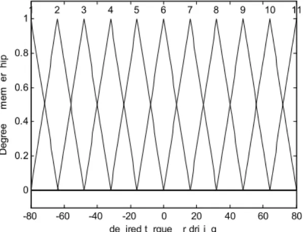
For designing the controller, we choose 11 membership functions for two inputs and one output. These membership functions have been marked as 1 to 11 and shown in Figs. 2~4. The fuzzy rules are defined in Table 1.
-80 -60 -40 -20 0 20 40 60 80 0 0.2 0.4 0.6 0.8 1
desired torque for driving
D eg re e of m em be rs hi p 1 2 3 4 5 6 7 8 9 10 11
Fig. 2. Membership functions of desired torque for driving (input1) 0.64 0.65 0.66 0.67 0.68 0.69 0.7 0 0.2 0.4 0.6 0.8 1 SOC D eg re e of m em be rs hi p 1 2 3 4 5 6 7 8 9 10 11
0 10 20 30 40 50 60 70 0 0.2 0.4 0.6 0.8 1
engine throttle angle
D eg re e of m em be rs hi p 1 2 3 4 5 6 7 8 9 10 11
Fig. 4. Membership functions for engine throttle angle
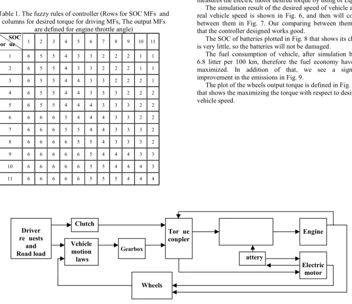
Table 1. The fuzzy rules of controller (Rows for SOC MFs and columns for desired torque for driving MFs, The output MFs
are defined for engine throttle angle) SOC torque 1 2 3 4 5 6 7 8 9 10 11 1 6 5 5 4 3 3 2 2 2 1 1 2 6 5 5 4 3 3 2 2 2 1 1 3 6 5 5 4 4 3 3 2 2 2 1 4 6 5 5 4 4 3 3 3 2 2 2 5 6 5 5 4 4 4 3 3 3 2 2 6 6 6 6 5 4 4 4 3 3 2 2 7 6 6 6 5 5 4 4 3 3 3 2 8 6 6 6 6 5 5 4 3 3 3 2 9 6 6 6 6 6 5 4 4 4 3 3 10 6 6 6 6 6 5 5 4 4 4 3 11 6 6 6 6 6 5 5 5 4 4 4
4. Simulation and Results
In the simulations, we have used ADVISOR software, available in [7], in which certain blocks have been replaced by dynamic equations, given in previous sections of this paper.
The block diagram of the proposed method is presented in Fig. 5. The input of clutch is its states, that involves: disengaged, slipping, and engaged, that driver commands. The inputs of the vehicle motion laws block are the desired vehicle speed and torque. The vehicle speed that is output of wheels block will be compared with the desired vehicle speed. The input of the wheels block is the torque that is summation of engine and motor output torque.
The fuzzy controller that we designed in section 3, with respect of the desired torque and the SOC of battery, controls the throttle angle degree of engine and therefore its output torque will be controlled. Then the torque coupler unit subtracts the real engine output torque, from the desired torque and measures the electric motor desired torque by using of Eq. (8).
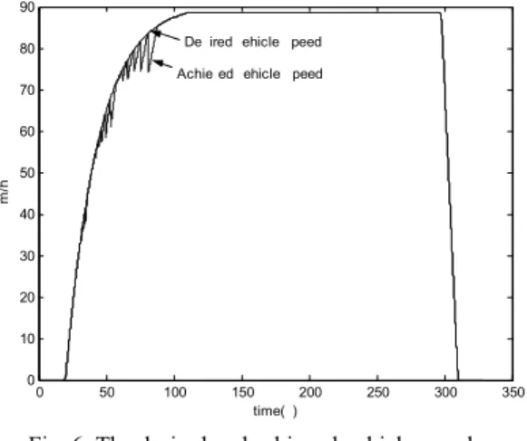
The simulation result of the desired speed of vehicle and the real vehicle speed is shown in Fig. 6, and then will compare between them in Fig. 7. Our comparing between them show that the controller designed works good.
The SOC of batteries plotted in Fig. 8 that shows its changes is very little, so the batteries will not be damaged.
The fuel consumption of vehicle, after simulation became 6.8 litter per 100 km, therefore the fuel economy have been maximized. In addition of that, we see a significant improvement in the emissions in Fig. 9.
The plot of the wheels output torque is defined in Fig. 11 that shows the maximizing the torque with respect to desired vehicle speed.
Fig. 5. The block diagram of parallel hybrid electric vehicle with its controller
Fuzzy
controller
Engine Vehicle motion laws Gearbox Clutch Electric motor Torque coupler Driver requests andRoad load Battery
0 50 100 150 200 250 300 350 0 10 20 30 40 50 60 70 80 90 km /h time(s) Achieved vehicle speed
Desired vehicle speed
Fig. 6. The desired and achieved vehicle speed
0 50 100 150 200 250 300 350 -2 0 2 4 6 8 10 ve hi cl e sp ee d (k m /h ) time (s)
Difference between requested and achieved speeds
Fig. 7. Difference between requested and achieved speeds
0 50 100 150 200 250 300 350 0.684 0.686 0.688 0.69 0.692 0.694 0.696 0.698 0.7 S O C time(s)
Fig. 8. The SOC of batteries
0 50 100 150 200 250 300 350 0 0.5 1 1.5 2 em is si on s time(s)
Fig. 9. emission results (HC, CO, NOx, and PM)
0 50 100 150 200 250 300 350 -2000 -1000 0 1000 2000 3000 4000 5000 w he el s ou tp ut (N .m ) time(s)
Fig. 10. The wheels output torque
5. Conclusions
We believe that the above described parallel hybrid electric vehicle control presents an optimal control that achieves three control goals: 1. maximizing vehicle torque, 2. minimizing fuel consumption, and 3. minimizing exhaust emissions. Our simulation study proved our idea. For simulation we used ADVISOR software, but because of its static models, we used our dynamic models for some of its blocks.
6. References
[1] I. Husain, Electric and Hybrid Vehicles: Design
Fundamentals, CRC PRESS, 2003
[2] M. Ehsani, M. Rahman and H. Toliyat, “Propulsion System Design of Electric and Hybrid Vehicles”, IEEE
Transactions on Industrial Electronics, Vol. 44, No. 1, Feb.
1997
[3] ATVP-Advanced Powertrains and Engines (II),
[4] P. F. Puleston, S. Spurgeon and Xiao Yun Lu, “A nonlinear sliding mode control framework for engine speed control”,
Proceedings of the fourteenth International Symposium of Mathematical Theory of Networks and Systems, MTNS 2000,
Perpignan France, 19-23 June. 2000
[5] B. K. Powell and T. E. Pilutti, “ A Range Extender
Hybrid Electric Vehicle dynamic model”, Decision and
Control, 1994., Proceedings of the 33rd IEEE Conference on, Volume: 3, Pages:2736 – 2741, 14-16 Dec. 1994
[6] B. K. Powell, K. E. Bailey and S. R. Cikanek, “ Dynamic
modeling and control of hybrid electric vehicle powertrain systems”, Control Systems Magazine, IEEE, Volume: 18, Issue: 5,Pages:17 – 33, Oct. 1998
[7] ADVISOR 2002 software, Available:
http://www.ctts.nrel.gov
[8] National Renewable Energy Laboratory. ADVISOR Documentation. Golden Co. [Online]. Available: http://www.ctts.nrel.gov/analysis/
[9] N. J. Schouten, M. A. Salman and N. A. Kheir, “Energy management strategies for parallel hybrid vehicles using fuzzy logic”, Control Engineering Practice, Volume: 11 , pages: 171-177, Feb. 2003
[10] E. Cerruto, A. Consoli, A. Raciti and A. Testa, “ Energy
flows management in hybrid vehicles by fuzzy logic controller”, Electrotechnical Conference, 1994. Proceedings., 7th Mediterranean, Pages:1314 – 1317, 12-14
April 1994
[11] Hyeoun-Dong Lee and Seung-Ki Sul,
“Fuzzy-logic-based torque control strategy for parallel-type hybrid electric vehicle”, Industrial Electronics, IEEE Transactions
on, Volume: 45, Issue: 4, Pages:625 – 632, Aug. 1998
[12] Hyeoun-Dong Lee, Euh-Suh Koo, Seung-Ki Sul, Joohn-Sheok Kim, M. Kamiya, H. Ikeda, S. Shinohara and H. Yoshida, “ Torque control strategy for a parallel-hybrid
vehicle using fuzzy logic”, Industry Applications Magazine,