INTRODUCTION
Visual evoked potentials (VEPs) are evoked electro-physiological potentials that can be extracted by signal averaging from electroencephalographic activities re-corded at the scalp. After VEPs were first described, VEPs was extremely valuable for evaluating sensory and per-ceptual visual processing in both research and clinical fields [1,2]. There are two basic types of VEP, namely, pat-tern reversal (PR) and flash VEPs. In particular, PR-VEP is preferred for most clinical purposes [3] because its
re-Annals of Rehabilitation Medicine Ann Rehabil Med 2016;40(2):334-340
pISSN: 2234-0645 • eISSN: 2234-0653 http://dx.doi.org/10.5535/arm.2016.40.2.334
Received August 3, 2015; Accepted August 31, 2015 Corresponding author: Sang Chul Lee
Department of Rehabilitation Medicine and Research Institute of Rehabilitation Medicine, Yonsei University College of Medicine, 50 Yonsei-ro, Seodaemun-gu, Seoul 03722, Korea
Tel: +82-2-2228-3711, Fax: +82-2-363-2795, E-mail: [email protected] This is an open-access article distributed under the terms of the Creative Commons Attribution Non-Commercial License (http://creativecommons. org/licenses/by-nc/4.0) which permits unrestricted noncommercial use, distribution, and reproduction in any medium, provided the original work is properly cited.
Copyright © 2016 by Korean Academy of Rehabilitation Medicine
Visual Evoked Potential Using Head-Mounted
Display Versus Cathode Ray Tube: A Pilot Study
Hyo Seon Choi, MD1, Sang Hee Im, MD, PhD2, Yong Kyun Kim, MD, PhD3, Sang Chul Lee, MD, PhD1
1Department of Rehabilitation Medicine and Research Institute of Rehabilitation Medicine,
Yonsei University College of Medicine, Seoul; 2Department of Rehabilitation Medicine, CHA Bundang Medical Center, CHA University, Seongnam; 3Department of Physical Medicine and Rehabilitation, Myongji Hospital,
Seonam University College of Medicine, Goyang, Korea
Objective To present a new stimulation method based on the use of a head-mounted display (HMD) during pattern reversal visual evoked potential (PR-VEP) testing and to compare variables of HMD to those of conventional cathode ray tube (CRT).
Methods Twenty-three normal subjects without visual problems were recruited. PR-VEPs were generated using CRT or HMD stimuli. VEP outcome measures included latencies (N75, P100, and N145) and peak-to-peak amplitudes (N75–P100 and P100–N145). Subjective discomfort associated with HMD was determined using a self-administered questionnaire.
Results PR-VEPs generated by HMD stimuli showed typical triphasic waveforms, the components of which were found to be correlated with those obtained using conventional CRT stimuli. Self-administered discomfort questionnaires revealed that HMD was more comfortable in some aspects. It allowed subjects to concentrate better than CRT.
Conclusion The described HMD stimulation can be used as an alternative to the standard CRT stimulation for PR-VEPs. PR-VEP testing using HMD has potential applications in clinical practice and visual system research because HMD can be used on a wider range of subjects compared to CRT.
sults are less variable than those elicited by other stimuli. On the other hand, although flash VEP produces more variable inter-subject results than PR-VEP, flash VEP is occasionally useful, especially for patients who are un-able or unwilling to cooperate during PR-VEP testing and for patients with sedated status during surgery or with impaired consciousness [3]. A flash stimulator can also be used for patients who are unable to maintain a steady focus due to behavioral or neuromuscular difficulties and those whose visual acuities preclude shorter distance or larger check-patterned stimulus [4].
During conventional PR-VEP testing, pattern stimuli are displayed on a cathode ray tube (CRT) monitor. Subjects must be seated upright and observe the monitor carefully for 10 to 20 minutes. However, when a patient is unable to sit upright due to orthostatic hypotension or muscu-loskeletal problems such as pain, severe scoliosis, trunk muscle weakness, or spinal fracture, flash VEP is the only alternative.
Head-mounted displays (HMDs) present symbolic or pictorial information to the user by using one or two miniature visual displays mounted onto the head by some means. If implemented properly, HMDs offer ad-vantages such as increased situational awareness and ease of mobility [5]. In addition, HMDs can produce an individual environment when worn as goggles [6]. Visual stimuli presented using HMDs are separated from the environment. They can maintain uniform size and sub-ject/screen distance regardless of subject posture. Thus, HMDs are increasingly being considered for use in a wide variety of medical applications including surgery [7].
An alternative method of VEP testing is required for those who are unable to undergo PR-VEP studies due to reduced ability to concentrate or inability to maintain upright position. We considered that if HMD system is utilized for VEP studies, PR-VEP would be possible in a
subset of patients for whom conventional PR-VEP is not possible.
The current study was designed to investigate the possi-bilities and limitations of PR-VEP testing using HMD. We hypothesized that such a method to deliver visual stimu-lus using HMD could offer a valid alternative for classic PR-VEP testing. It has potential applications in clinical practice. In addition, it might be useful for those who are involved in research on visual pathways.
MATERIALS AND METHODS
Subjects
A total of 23 normal healthy subjects participated in this study with a mean age of 27.6 years (standard deviation, 2.8; range, 23–32 years), including 12 (52.2%) males. All participants had normal or corrected-to-normal vision without history of ophthalmologic disease. They all pro-vided written informed consent after receiving an expla-nation of study goals. The study protocol was approved by the ethics committee of Myongji Hospital.
Stimuli
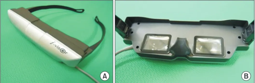
PR-VEP was performed using a CRT monitor (LG Elec-tronics, Seoul, Korea) or a HMD (Daeyang E&C, Seoul, Korea). The HMD consisted of two 1.5-cm organic light emitting diode (OLED) microdisplays mounted in a spec-tacle-like frame connected to a personal computer (Fig. 1). This unit offered a virtual experience of a 152.4-cm screen viewed from a distance of 200.0 cm.
Full-field PR-VEP test was performed using a monocu-lar stimulus on both eyes of each subject. Each subject underwent test using HMD and CRT monitor. The orders of presentation were randomized among subjects. Tests were performed after allowing a rest period of approxi-mately 30 minutes. Stimuli were created by reversing
A B
Fig. 1. A picture of head-mounted
display. (A) The front side of the unit. (B) An inside view showing the organic light emitting diode (OLED) monitors.
a checkerboard pattern display. Both stimulators were driven by a computer that generated the pattern and al-lowed adjustments for check size, overall brightness, and contrast.
PR-VEP using CRT was performed as follows. A subject was seated comfortably in a quiet darkened room 100 cm from CRT. The subject was instructed to fixate on a small dot at its center with one eye. The other eye was covered with a patch. Subjects were carefully observed during the procedure to ensure adequate fixation. A checker-board pattern with 90% contrast was generated on CRT. The screen had a mean luminance of 50.5 cd/m2. Checks
were phase reversed at 2 Hz. Checks were 60×45 minute of arc in size. The total visual angle was 15.4o×11.6o (16×16
checks).
PR-VEP using HMD was performed as follows. Its stim-ulating image was basically the same program as CRT image. Before VEP test, each subject was seated comfort-ably. After putting HMD on the subject, it was adjusted to produce the clearest image. Subjects were instructed to fixate on a small dot at the center of the image with one eye while the other eye was covered with a patch. The screen had a mean luminance of 50.5 cd/m2. A
checker-board pattern with 90% contrast was generated on HMD. Checks were also phase reversed at 2 Hz. As HMD was not specifically manufactured for VEP testing, the device offered only a virtual experience of watching a 152.4-cm screen from a distance of 200.0 cm. The check size was also fixed to 60×45 min of arc with a total visual angle of 61.7o×46.2o (32×32 checks). However, due to difference
in perceived images and distances, it was inevitable to use different check numbers of pattern between CRT and HMD.
Recordings
PR-VEP testing was performed using Medelec Syn-ergy EMG and EP systems ver. 10 (Oxford Instruments, Hawthorne, NY, USA). PR-VEP recordings were obtained using an active electrode Oz (10–20 International sys-tem) referenced against mid-frontal electrode Fz (10–20 International system). Ground electrode was placed at Cz (10–20 International system). Ag-AgC1 cup electrodes were used. Electrode impedance was kept below 5 kΩ. The incoming signal was amplified 10,000 times and passed through 1 to 100 Hz band-pass filter. A total of 250 responses were summed with analysis time of 300
ms. At least two trials were performed per eye to ensure potential reproducibility and coherence. Peak latencies and peak-to-peak amplitudes of major components were measured. Peak latencies of N75, P100, and N145 were acquired. Peak-to-peak amplitudes were calculated from N75 to P100 (N75–P100) and from P100 to N145 (P100– N145).
Assessment of discomfort
Subjects were asked to complete a discomfort question-naire based on an International Standard after tests using each device [8]. The questionnaire consisted of seven scales that addressed discomforts associated with eye dryness, eyelid irritation, focusing, general eye problems, posture, headache, and concentration. Answers were scored on a Likert-type scale of 1 to 5. Individual scores for the seven scales were summed. Result score ranged from 5 to 35, with higher scores indicating greater dis-comfort.
Data analysis
Results from CRT were compared to those from HMD. To determine the difference in terms of latencies and amplitudes of responses between two different stimuli, paired t-test was used. Pearson correlation coefficients were calculated to determine the association between results elicited by the two stimuli. Independent t-test was used to analyze discomfort differences between the two stimulation methods based on questionnaire. Data were analyzed using Statistics Package for Social Sci-ences (SPSS) ver. 13.0 for Windows (SPSS Inc., Chicago, IL, USA). Statistical significance was considered when p-value was less than 0.05.
RESULTS
VEP findings
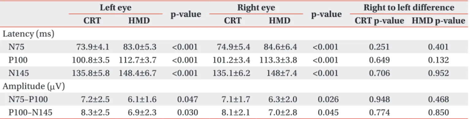
VEP waveforms were elicited by CRT and HMD stimuli. PR-VEPs of each stimulus showed typical triphasic wave-forms characterized by three dominant peaks consisting of N75, P100, and N145 (Fig. 2). VEP latencies from CRT were significantly (p<0.05) shorter than those from HMD (Table 1). VEP amplitudes from CRT were also signifi-cantly (p<0.05) greater than those from HMD. No right to left side difference (p>0.05) in latency or amplitude was observed for either HMD or CRT. All results from CRT
stimulation were correlated (p<0.05) with those from HMD (Table 2).
Procedure associated discomfort
Questionnaire responses were obtained from the two
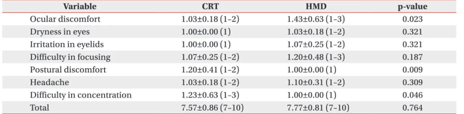
stimulation modalities (Table 3). Mean total scores of CRT and HMD based tests were 7.57±0.86 and 7.77±0.81, respectively. General eye discomfort of HMD had a higher mean score than the other six scales. However, no individual mean score exceeded 3. When the two modali-ties were compared in terms of questionnaire responses, CRT was found to result in more postural discomfort and concentration difficulty. However, CRT had less ocular discomfort than HMD.
DISCUSSION
This study was designed to present a new stimulation method using HMD during PR-VEP test and to compare variables of HMD to those of conventional CRT. PR-VEPs generated by HMD showed typical triphasic waveforms. Their components were correlated with those obtained by conventional CRT. We hope that the use of HMD might widen the application of PR-VEP testing to patients who
Fig. 2. Waveform of pattern
ob-tained during reversal-visual evoked potential (PR-VEP) testing using. (A) A cathode ray tube (CRT). (B) A head-mounted display (HMD). The PR-VEPs obtained in both CRT and HMD showed well-defined N75, P100, and N145.
A B
Table 1. Differences between HMD and CRT stimulation in terms of PR-VEP latencies and amplitudes
Left eye
p-value Right eye p-value Right to left difference
CRT HMD CRT HMD CRT p-value HMD p-value Latency (ms) N75 73.9±4.1 83.0±5.3 <0.001 74.9±5.4 84.6±6.4 <0.001 0.251 0.401 P100 100.8±3.5 112.7±3.7 <0.001 101.2±3.4 113.3±3.8 <0.001 0.649 0.132 N145 135.8±5.8 148.4±6.7 <0.001 135.1±6.2 148±7.4 <0.001 0.706 0.952 Amplitude (µV) N75–P100 7.2±2.5 6.1±1.6 0.047 7.1±1.7 6.3±2.0 0.026 0.948 0.468 P100–N145 8.3±2.5 6.9±2.3 0.030 8.1±2.1 7.0±2.8 0.045 0.774 0.850 Values are presented as mean±standard deviation.
HMD, head-mounted display; CRT, cathode ray tube; PR-VEP, pattern reversal-visual evoked potential.
Table 2. Pearson correlation coefficients between VEP variables obtained from using HMD and those obtained from using CRT
Component Left eye p-value Right eye p-value
Latency N75 0.423 0.045 0.553 0.008 P100 0.569 0.005 0.786 <0.001 N145 0.461 0.035 0.459 0.032 Amplitude N75–P100 0.450 0.041 0.486 0.025 P100–N145 0.619 0.003 0.532 0.009 VEP, visual evoked potential; HMD, head-mounted dis-play; CRT, cathode ray tube.
are not suitable candidates for conventional PR-VEP. Al-though this new stimulation method cannot be applied to patients with severe cognitive impairment, it can be used for almost all patients who have difficulty in sitting. It also has the advantages in size with transportability over CRT monitor. It was expected that normal VEP elicited by HMD would be almost identical to that elicited by CRT. The components of VEP waveforms generated by the two kinds of stimuli were analyzed. Our results showed that the two different stimuli produced correlative results, although CRT stimulus generated shorter latency and higher amplitude.
VEPs are used extensively for assessing visual pathways. They can be used to distinguish normal brain from isch-emic brain [9,10]. The range of disorders that may affect VEPs is vast, including multiple sclerosis, trauma, tu-mors, and stroke [11]. In some cases, VEP is more useful and sensitive than magnetic resonance imaging in terms of functional evaluations of optic nerves for the diagnosis of multiple sclerosis. Magnetic resonance imaging may not show demyelinating changes in the optic nerve [11]. PR-VEP can show relatively high intra- and inter-subject reliabilities in comparison to flash VEP [3]. Therefore, VEP is the preferred procedure in most cases. PR-VEP consists of N75, P100, and N145 peaks [3]. PR-VEP usu-ally shows triphasic potential with a major positive peak flanked by two smaller negative peaks. A stereotypic VEP with the appropriate peaks labeled is shown in Fig. 2A.
Since many factors can affect VEP [3,12], the standard-ization of VEP measurement and reporting is essential if information is to be exchanged between laboratories. In particular, standardization of stimulus parameters is crit-ical in this context [12,13]. VEP testing standards issued
by the International Society for Clinical Electrophysiology of Vision (ISCEV) can be used to define field size, pattern element size, mean luminance, contrast, and presenta-tion rate for PR-VEP tests [3]. For convenpresenta-tional PR-VEP test with CRT, stimulus luminance can be measured us-ing a photometer [14]. The ISCEV standard recommends mean luminance of >40 cd/m2 and contrast >75% [3].
Previous studies have shown that the latency and the amplitude of P100 are significantly affected by pattern lu-minance, contrast, and checks [15]. Essentially, P100 la-tency is increased as pattern luminance is decreased [16]. P100 amplitudes can be reduced and latencies can be increased by reducing contrast [17]. Furthermore, plots of P100 latency versus check size are U-shaped [17,18].
The HMD used in the present study was set to mean luminance of >50 cd/m2 with 90% contras. It should be
mentioned that we were unable to properly measure or calibrate HMD stimulation using a photometer. During conventional PR-VEP test, eye to monitor distance is 70 to 100 cm to reduce the likelihood of pattern defocusing [4]. However, in the present study, although check size and visual arc of HMD were adjustable, virtual object distance (200.0 cm) was not adjustable. Thus, although check size was the same for both stimuli in terms of sub-tended angle, the longer distance setting of HMD may have resulted in longer latency and lower amplitude. Minute head movements during test could also change response to HMD.
We wanted to know whether there was discernable dif-ference between CRT and HMD displays in terms of user comfort. The complete questionnaire revealed that HMD had some subjective advantages. For example, it was eas-ier to concentrate. In addition, it allowed more positional
Table 3. Questionnaire responses regarding comfort factors
Variable CRT HMD p-value Ocular discomfort 1.03±0.18 (1–2) 1.43±0.63 (1–3) 0.023 Dryness in eyes 1.00±0.00 (1) 1.03±0.18 (1–2) 0.321 Irritation in eyelids 1.00±0.00 (1) 1.07±0.25 (1–2) 0.321 Difficulty in focusing 1.07±0.25 (1–2) 1.20±0.48 (1–3) 0.187 Postural discomfort 1.20±0.41 (1–2) 1.00±0.00 (1) 0.009 Headache 1.03±0.18 (1–2) 1.10±0.31 (1–2) 0.309 Difficulty in concentration 1.23±0.63 (1–3) 1.00±0.00 (1) 0.046 Total 7.57±0.86 (7–10) 7.77±0.81 (7–10) 0.764
Values are presented as mean±standard deviation (range). CRT, cathode ray tube; HMD, head-mounted display.
freedom (Table 3). Conventional CRT was more difficult to concentrate due to distractions caused by objects around the monitor.
It is well understood that the inherent trade-off among resolution, eye relief, and screen size can severely limit the image quality of screen-based HMD units [19]. The visual effects of HMDs on users have been studied ex-tensively. Concerns have been raised regarding the side effects of HMDs [5,20]. These effects include stimulator sickness due to vestibular-visual conflicts, accommoda-tive difficulties, and binocular function difficulties with associated eye-strain [21]. Since HMD screen proximity to the eye can degrade eye relief, eye fatigue is of par-ticular concern. In fact, it was found that HMD was as-sociated with more subjective ocular discomfort in the present study. However, no mean scale score exceeded 3. The use of HMD would have been curtailed if the mean scale score exceeded 3 (Table 3). In addition, the total duration of VEP testing in the present study was less than 20 minutes. Its shortcomings were well tolerated by all 23 participants.
The study has some limitations. First, the small number of participants in this study could not allow us to com-pare VEP results according to age or sex. A wide range of age could increase the variance of VEPs between the two methods. Second, HMD resulted in a potential of longer latency and smaller amplitude than CRT. Although dif-ferent results were obtained, this was largely expected due to different test settings. However, we prefer to place emphasis on the correlation observed between the two stimulation modalities because we were interested in the potential usefulness of HMD for PR-VEP as an alternative to CRT.
HMD’s potential value as an alternative stimulation method is obvious. Thus, we intend to further test the sensitivity, specificity, and reliability in the context of PR-VEP versus conventional PR-VEP. HMD units have several definite benefits, namely, its weight, transport-ability, small size, and the ability to adjust posture. Thus, although HMD cannot yet fully replace CRT, unique ad-vantages of HMD can widen the application of PR-VEP testing for patients who are not suitable candidates for conventional PR-VEP, especially those who have difficulty in sitting. In terms of clinical applications, modifications of HMD are required to optimize test result quality. Fur-thermore, standardization of test methods and
adjust-ment of test parameters are needed to determine the ap-propriate age-related normative values for HMDs.
In conclusion, the results of this pilot study were ob-tained by using a novel visual stimulation method during PR-VEP testing. The results of experiments using HMD revealed statistically meaningful correlations with those using CRT. Therefore, we believe that HMD could play a role as a useful alternative or supplement to standard CRT stimulation in PR-VEP testing.
CONFLICT OF INTEREST
No potential conflict of interest relevant to this article was reported.
REFERENCES
1. Cobb WA, Dawson GD. The latency and form in man of the occipital potentials evoked by bright flashes. J Physiol 1960;152:108-21.
2. Vaughan HG Jr, Hull RC. Functional relation between stimulus intensity and photically evoked cerebral re-sponses in man. Nature 1965;206:720-2.
3. Odom JV, Bach M, Barber C, Brigell M, Marmor MF, Tormene AP, et al. Visual evoked potentials standard (2004). Doc Ophthalmol 2004;108:115-23.
4. Jeffrey LC, Goldberg G. Central nervous system elec-trophysiology. In: DeLisa JA, Gans BM, Walsh NE, et al., editors. Physical medicine and rehabilitation: principles and practice. 4th ed. Philadelphia: Lippin-cott Williams & Wilkins; 2005. p. 105-37.
5. Velger M. Helmet-mounted displays and sights. Bos-ton: Artech House; 1998. p. 10-5.
6. Hanprasertpong C, Koizumi Y, Aoyagi M, Kimura M, Yagi T. A head-mounted visual stimulator for neuroto-logical examination. Auris Nasus Larynx 2004;31:379-82.
7. Melzer JE, Moffitt K. HMD design: putting the user first. In: Melzer JE, Moffitt K, editors. Head mounted displays: designing for the user. New York: McGraw-Hill; 1997. p. 1-16.
8. International Organization for Standardization. Inter-national standard-ergonomic requirements for office work with visual display terminals (VDTs). Part 3: visu-al display requirements. Geneva: Internationvisu-al Orga-nization for Standardization; 1992. (ISO 9241-3:1992).
9. Oosterhuis HJ, Ponsen L, Jonkman EJ, Magnus O. The average visual response in patients with cerebrovas-cular disease. Electroencephalogr Clin Neurophysiol 1969;27:23-34.
10. Klassen AC, Heaney LM, Lee MC, Torres F. Hypercap-nic alteration of visual evoked responses in acute cere-bral infarction. Arch Neurol 1979;36:627-9.
11. Misulis KE, Fakhoury T. Spehlmann’s evoked poten-tial primer. 3rd ed. Boston: Butterworth-Heinemann; 2001. p. 137-55.
12. Bodis-Wollner I, Ghilardi MF, Mylin LH. The impor-tance of stimulus selection in VEP practice: the clini-cal relevance of visual physiology. In: Cracco RQ, Bodis-Wollner, editors. Evoked potentials. New York: Liss; 1986. p. 15-27.
13. Celesia GG, DeMarco PJ Jr. Anatomy and physiology of the visual system. J Clin Neurophysiol 1994;11:482-92.
14. Brigell M, Bach M, Barber C, Kawasaki K, Kooijman A. Guidelines for calibration of stimulus and recording parameters used in clinical electrophysiology of vi-sion. Calibration Standard Committee of the Interna-tional Society for Clinical Electrophysiology of Vision (ISCEV). Doc Ophthalmol 1998;95:1-14.
15. Celesia GG. Evoked potential techniques in the
evalu-ation of visual function. J Clin Neurophysiol 1984;1:55-76.
16. Tobimatsu S, Celesia G, Cone S. Effects of pupil diam-eter and luminance changes on pattern electroreti-nograms and visual evoked potentials. Clin Vision Sci 1988;2:293-302.
17. Tobimatsu S, Kurita-Tashima S, Nakayama-Hiromatsu M, Akazawa K, Kato M. Age-related changes in pat-tern visual evoked potentials: differential effects of lu-minance, contrast and check size. Electroencephalogr Clin Neurophysiol 1993;88:12-9.
18. Kurita-Tashima S, Tobimatsu S, Nakayama-Hiromatsu M, Kato M. Effect of check size on the pattern reversal visual evoked potential. Electroencephalogr Clin Neu-rophysiol 1991;80:161-6.
19. Patterson R, Winterbottom MD, Pierce BJ. Perceptual issues in the use of head-mounted visual displays. Hum Factors 2006;48:555-73.
20. Mon-Williams M, Wann JP, Rushton S. Binocular vi-sion in a virtual world: visual deficits following the wearing of a head-mounted display. Ophthalmic Physiol Opt 1993;13:387-91.
21. Peli E. The visual effects of head-mounted display (HMD) are not distinguishable from those of desk-top computer display. Vision Res 1998;38:2053-66.