© Korean Powder Metallurgy Institute 767
-1. Introduction
The thermal management of electronic products has become a major challenge for packaging industries. One of the solutions is the employment of vapor chambers, in which the large-area base is in contact with the heat source to provide a fast spreading of the heat generated by the heat source. Inside the chamber, the wick structure provides heat dissipation like the heat pipe through the two-phase transformation of water. The water vapor is then condensed at the top plate, which is connected to cooling fins with large surface areas [1-3]. In the conventional vapor chamber, the copper fins are soldered or brazed to the top plate of the box. These solder or brazed joints form a thermal barrier between the two adjacent copper components and deteriorate the overall heat dissipation performance. One way to eliminate these thermal barriers is to employ the metal injection molding (MIM) process to prepare the vapor chamber with cooling fins without any secondary joining process [4,5]. However, many challenges still remain. The objective of this study was thus to fabricate a MIM vapor chamber that incorporates cooling fins with large aspect ratios and to evaluate its thermal resistance.
2. Experimental and Results
The characteristics and morphologies of the Cu powder used in this study are shown in Table 1 and Figure 1, respectively. The feedstock was prepared using a multi-component binder system and was injection molded into a heat sink. The heat sink contained fins with four different
thicknesses, and the corresponding aspect ratios were 8.8, 11.7, 16.0, and 17.6, respectively. The molded green part was solvent debound, thermally debound, and then sintered in a hydrogen atmosphere at 1050 for ℃ 2 hours.
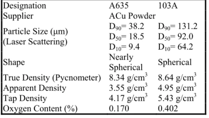
Table 1. The characteristics of the A635 and 103A copper powders.
Designation A635 103A
Supplier ACu Powder
D90= 38.2 D90= 131.2 D50= 18.5 D50= 92.0 Particle Size (µm)
(Laser Scattering) D
10= 9.4 D10= 64.2 Shape Nearly Spherical Spherical True Density (Pycnometer) 8.34 g/cm3 8.64 g/cm3 Apparent Density 3.55 g/cm3 4.95 g/cm3 Tap Density 4.17 g/cm3 5.43 g/cm3 Oxygen Content (%) 0.170 0.402
Fig. 1. The morphologies of the (a) A635 Cu powder and (b) 103A Cu powder under SEM.
2006 POWDER METALLURGY World Congress
B02-08-4
Thermal Dissipation Performance of a Heat Sink/Vapor Chamber
Prepared by Metal Injection Molding Process
Bor-Yuan Chena and Kuen-Shyang Hwangb
Department of Materials Science and Engineering, National Taiwan University 1, Roosevelt Road, Sec. 4, Taipei, 106, Taiwan, R.O.C.
a
[email protected], [email protected] Abstract
In this study, copper vapor chambers with built-in cooling fins, which eliminated the soldered or brazed joints in the conventional vapor chamber, were fabricated using the metal injection molding process. The results show that with optimized molding parameters, fins with an aspect ratio up to 18 could be produced. After sintering, the densities of the fin and chamber reached 96%. With only 32 cooling fins and a small fan installed, the thermal resistance of the heat sink was
1.156 /W, and the power dissipation was 40W when the junction temperature was 70 . When copper powder was sintered ℃ ℃
onto the chamber to make a vapor chamber, the thermal resistance decreased to 1.046 /W.℃
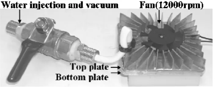
© Korean Powder Metallurgy Institute 768 -The upper element of the vapor chamber was made with the MIM heat sink. For the bottom element, the 32 cooling fins were cut off. To prepare the powder-mesh type of vapor chambers, the 103A Cu powder was loosely sintered at 850 for ℃ 1 hour onto the base copper plate, and a Cu mesh was then bent into the sawtooth shape and placed on top of the Cu powder wick. The mesh-mesh type, in which two sawtooth Cu meshes were overlapped orthogonally, was also prepared. The assembled vapor chamber was then connected to pipes and valves, as show in Figure 2, which were used for vacuuming and for water injection.
Fig. 2. The assembled vapor chamber for thermal resistance measurement.
To mold successfully a heat sink with high aspect ratio fins, optimized processing parameters without pressure holding were selected. The sintered densities of all the fins were close to about 96%, regardless of their thicknesses. The density of the base plate was also about 96%. This means that there should be no interconnected open pores in the specimen. Figure 3 and Figure 4 demonstrate the effect of the wick structure type and the amount of the water on the thermal performance. Figure 3 shows that the powder-mesh wick was better than the powder-mesh-powder-mesh type. Figure 4 indicates that when the porous wick was 100% filled with water, the lowest thermal resistance could be attained. When a fan was installed, the thermal resistance of both wick structures decreased significantly, as shown in Figure 4. With only 32 fins and 100% pores filled with water, the thermal resistance of the vapor chamber with the powder-mesh structure was 1.046 /W and the power dissipation ℃ was 42W when the junction temperature was 70 . In ℃ contrast, the thermal resistance of the straight heat sink was 1.156 /W. This indicated that the phase transformation of ℃ water had occurred and enhanced the thermal dissipation of the chamber. Both Figure 3 and Figure 4 also indicated that the water content is critical in obtaining the optimum thermal performance. When there was too much water, the radius of curvature of the water profile at the surface was quite flat. This reduced the capillary pressure to draw condensed water from the top plate to the bottom plate, the evaporation end of the chamber. When the working fluid was too low, dry-out phenomena occurred and impaired the thermal dissipation capability.
Fig. 3. Comparison on the thermal resistances of vapor chambers with different wick structures and amounts of water. (No fan installed.)
Fig. 4. Comparison on the thermal resistances of vapor chambers with different wick structures and amounts of water. (With fan installed.)
3. Summary
With adjusted processing parameters, 0.42mm thick cooling fins with an aspect ratio of 17.6 can be produced successfully. This demonstrates that the solder or brazed joints can be eliminated. Using a powder-mesh structure as the wick and adjusted amounts of water, a thermal resistance of 1.046 /W was attained℃ , and the power dissipation was 42W when the junction temperature was 70 .℃
4. References
1. C. J. M. Lasance and R. E. Simons, ElectronicsCooling, 11[4], (2005).
2. M. Vogel and G. Xu, ElectronicsCooling, 11[1], (2005). 3. I. Sauciuc; G. Chrysler; R. Mahajan and R. Prasher,
IEEE Trans. Compon. Packag. Technol., 25[4], pp. 621-628, (2002).
4. J. L. Johnson, L. K. Tan, R. Bollina, P. Suri and R. M. German, Powder Metal., 48[2], pp. 123-128, (2005). 5. B. H. Shropshire, PMT, K. Klatt, S. T. Lin and T. Y.