Volume 2013, Article ID 521383,7pages http://dx.doi.org/10.1155/2013/521383
Research Article
Robust People Tracking Using an Adaptive Sensor Fusion
between a Laser Scanner and Video Camera
Yeong Nam Chae,
1Yeong-Jae Choi,
1Yong-Ho Seo,
2and Hyun S. Yang
11Department of Computer Science, KAIST, 291 Daehak-ro, Yuseong-gu, Daejeon 305-701, Republic of Korea
2Department of Intelligent Robot Engineering, Mokwon University, 88 Doanbok-ro, Seo-gu, Daejeon, Republic of Korea Correspondence should be addressed to Yong-Ho Seo; [email protected]
Received 25 January 2013; Accepted 28 February 2013 Academic Editor: Sabah Mohammed
Copyright © 2013 Yeong Nam Chae et al. This is an open access article distributed under the Creative Commons Attribution License, which permits unrestricted use, distribution, and reproduction in any medium, provided the original work is properly cited.
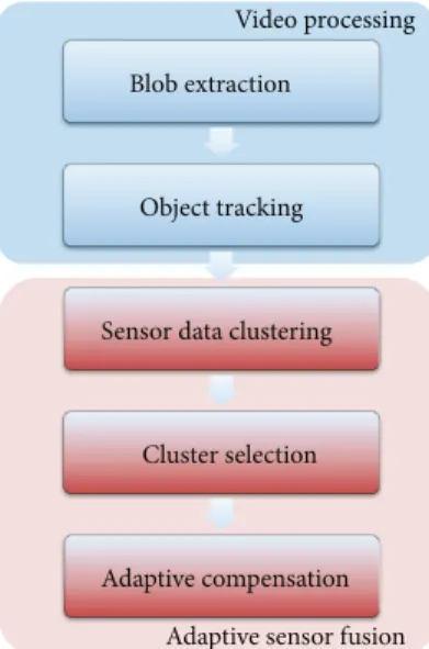
Robust detection and tracking in a smart environment have numerous valuable applications. In this paper, an adaptive sensor fusion method which automatically compensates for bias between a laser scanner and video camera is proposed for tracking multiple people. The proposed system comprises five components: blob extraction, object tracking, scan data clustering, a cluster selection, and updating the bias. Based on the position of object in an image, the proposed system determines the candidate scan region. Then, the laser scan data in the candidate region of an object is clustered into several clusters. A cluster which has maximum probability as an object is selected using a discriminant function. Finally, a horizontal bias between the laser scanner and video camera is updated based on the selected cluster information. To evaluate the performance of the proposed system, we show error analysis and two applications. The results confirm that the proposed system can be used for a real-time tracking system and interactive virtual environment.
1. Introduction
Robust detection and tracking in a smart environment have numerous valuable applications, such as recognizing human behavior for intelligent surveillance, monitoring, and analyz-ing. To monitor human activities such as location, identity, and behavior, robust detection and tracking are necessities in various environments.
In the people motion tracking area, the one side view, which comes from a single video image, is used to verify peoples’ actions. In diverse and sophisticated environments, there are numerous problems in a single video image. In ubiquitous environments, to perceive the motion of people, unfavorable conditions exist in single-sensor systems, such as illumination variation and shadow. To overcome these problems, many methods rely on fusing a number of sensors, such as the infrared cameras, laser range finders, and image cameras of many directions [1,2]. However, as various sensors are added, the object calibration is a very important issue in the object tracking area for the reliable detection and tracking of multiple objects [3].
To calibrate multi-sensors, an attempt using an extrin-sic calibration between the camera and the laser scanner was proposed in [3–6]. This approach uses a technique in which both sensors image a planar checkerboard target at unknown orientations. Even if the calibration is reliable, it is inconvenient to adjust for tracking people simultaneously. Furthermore, the checkerboard always should be used to calibrate this system.
To overcome these problems, we present an adaptive sensor fusion method between the laser scanner and video camera. In this proposed approach, our system does not need a checkerboard. As the configuration of the system, which consists of a laser scanner and video camera, changes to intuitive positions, the traditional system requires a recalibra-tion process. The proposed system, which has a background model, can compensate these sensor’s horizontal variations automatically.
The paper is organized as follows: in the next section, we briefly introduce the proposed system. In Section 3, we present a video processing method for tracking multiple
Adaptive sensor fusion Object tracking
Sensor data clustering
Cluster selection
Ad ti f i
Adaptive compensation
Figure 1: System overview.
objects. InSection 4, we present a detailed method to cali-brate laser scanner and video camera. Then, we present the results with real environmental data inSection 5. At last, we conclude inSection 6.
2. System Overview
The proposed system consists of the video processing and the adaptive sensor fusion as shown inFigure 1. To measure the position of objects in an image, we adopt Mixture of Gaussians-(MoGs-) [7] based blob extraction and inference-graph-based object tracking approach. Then laser, scan data in the candidate region from the result of the object tracking is clustered into several clusters. A cluster which has maximum probability as an object is selected using a discriminant function. Finally, a horizontal bias between the laser scanner and video camera is compensated based on selected cluster information.
3. Video Processing
In order to merge the laser scanner and video camera, the proposed system performs video processing in a prior part of the system. In order to measure the position of objects in an image, we developed an enhanced view-based multiple-object tracking system based on previous research [8,9]. In this section, we briefly introduce this multiple-object tracking system.
3.1. Blob Extraction. For segmentation, MoGs is widely used
due to the capability for adaptation to the various environ-mental changes like illuminations. But, the main problem of MoGs is that moving objects are learned as background when they stop. And thus it fails to segment objects stopped as foreground. In the proposed system, in order to segment an input image into a foreground and background, a modified MoGs [8] is used to keep moving objects segmented as
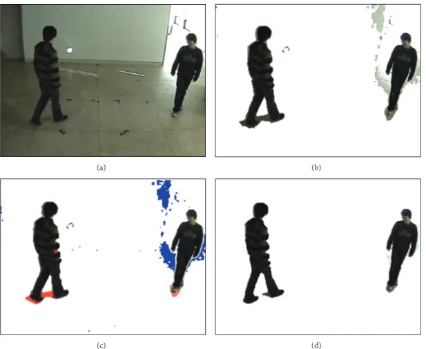
component are identified as pixels belonging to the objects stopped and they are put into an augmented mask. Third, the pixels in the augmented mask are added to the segmentation mask from the conventional MoGs. Fourth, the pixels in the augmented mask are removed from the augmented mask when the stopped objects start to move. This modified MoGs guarantees that the objects still identified as foreground, even when moving objects stopped. In order to remove shadows and highlights, we can adjust the intensity of a shadow pixel compared with a background model as shown inFigure 2(d). After removing shadows and highlights, when capturing foreground pixels at frame𝑡, they are clustered into a set of 𝐵𝑡= {𝑏𝑡
𝑖 | 𝑖 is an integer and 0 ≤ 𝑖}, where a blob 𝑏𝑖𝑡is an𝑖th
set of connected foreground pixels.
3.2. Object Tracking. A blob represents an object in the
ideal case. In the real environment, however, one object can have several blobs (fragmentation), and one blob can have multiple-objects (grouping). To deal with these problems, Choi et al. [9] adopt an online multiple object tracking framework. Figure 3 shows the overall procedure of this framework. First, detecting blob association events between 𝐵𝑡and𝐵𝑡−1can update the blob inference graph, labeling each vertex as fragment, object, and group. Finally, localization of objects can be captured by using the blob graph.
4. Adaptive Sensor Fusion
In this paper, we propose an adaptive method which com-pensates horizontal bias between the laser scanner and video camera. In order to merge the laser scanner and video camera adaptively, there are three steps in the proposed method. First, laser scan data in the candidate region of the object is clustered into several clusters. Second, a cluster which has maximum probability as an object is selected using a discriminant function. Finally, a horizontal bias between the laser scanner and video camera is updated based on selected cluster information.
4.1. Sensor Data Clustering. To match an object in an image
to laser scan data, we determine the candidate region in the laser scan data. The candidate region in the laser scan data can be determined based on the object position in an image. This candidate region(𝜃𝑙, 𝜃𝑟) is shown in the following equations:
𝜃𝑙= (1 − 𝜑) (90 + fov (−1 2+ 𝑜𝑙 𝜔) + bias) , 𝜃𝑟= (1 + 𝜑) (90 + fov (−12+𝑜𝜔𝑟) + bias) . (1)
In (1),𝜃𝑙and𝜃𝑟 are the left and right angle boundaries, respectively,𝑜𝑙denotes the left pixel position of an object,𝑜𝑟 denotes the right pixel position of an object,𝜔 refers to image
(a) (b)
(c) (d)
Figure 2: (a) An input image. (b) The result of foreground extraction. (c) Detected shadow (marked in red) and highlight (marked in blue). (d) The result of foreground extraction: an example of a figure without shadow or highlight.
Blob tracking Blob inference Blob inference graph updating graph labeling
Object localization Merge Association events Inference graph Labeled inference
graph Objecttracks
(𝑘 is the size of the sliding window and 𝑘 > 1)
𝑂 𝑂 𝑂 𝑂 𝐺 𝐺 {𝑂𝑎} {𝑂𝑏} {𝑂𝑎, 𝑂𝑏} 𝑂𝑡−𝑘+1 𝐵𝑡
lumped into several clusters by the nearest neighborhood clustering algorithm. We use the following equation as a threshold equation:
√𝑑MV(𝜃1)2+ 𝑑MV(𝜃2)2+ 2𝑑MV(𝜃1) 𝑑MV(𝜃2) cos (𝜃1− 𝜃2)
> 𝛿.
(2) In (2),𝑑MV(𝜃) refers to the distance from the measured
value of the laser scanner at angle𝜃, both 𝜃1and𝜃2are discrete angle values (0, 1, 2, . . . 180), and 𝛿 denotes the neighborhood distance threshold value, which is set as 2.5 feet (an average person’s stride length [10]). Using this threshold function, we classified the datum in 2.5 feet from each other as same cluster.
4.2. The Cluster Selection Method. In order to take an
appropriate cluster which has the greatest probability to be an object, the proposed system adapts the following discriminant function:
𝑚 = arg max
0≤𝑖≤𝑘 𝜃∈C∑𝑖
Δ (𝜃) . (3)
In (3),𝑘 denotes the number of clusters, and 𝐶𝑖 refers to the 𝑖th cluster. A discriminant function Δ is adapted to compare each cluster:
Δ (𝜃) = { { { { { { { { { 𝜃𝜔 2 𝜃 − 𝜃𝑐𝑑MAX BG, 𝑑BG MV(𝜃) > 𝛿, 𝜃𝜔 2 𝜃 − 𝜃𝑐𝑑BG MV(𝜃) , otherwise. (4)
In (4), dMAX BGdenotes the maximum distance from the
background model of the laser scan data,𝑑BG MV(𝜃) denotes
the difference between the background model and measured value at𝜃, 𝜃𝜔 refers to angular width, and𝜃𝑐 refers to the center angle of the candidate region(𝜃𝑙, 𝜃𝑟). These are shown in the following equations:
𝑑MAX BG = max
0≤𝜃≤180𝑑BG(𝜃) , (5)
𝑑BG MV(𝜃) = 𝑑BG(𝜃) − 𝑑MV(𝜃) , (6)
𝜃𝜔= 𝜃𝑙− 𝜃𝑟, (7)
𝜃𝑐= 𝜃𝑙+ 𝜃2 𝑟. (8)
In (5) and (6), 𝑑BG(𝜃) denotes the distance from the
background model of the laser scan data at𝜃. The background
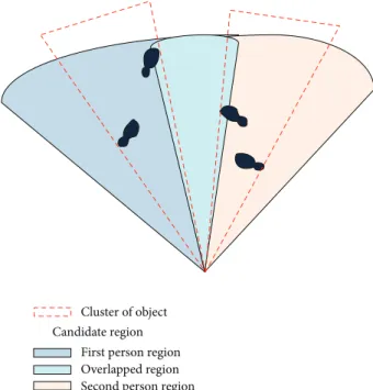
Overlapped region Second person region First person region Candidate region
Cluster of object
Figure 4: Example case of overlapping candidate regions.
Candidate region Cluster of object Target bias Center of cluster Center of candidate
Figure 5: The horizontal bias angle.
model of the laser scan data is similar to the traditional background model of the gray scale video stream. Consider
𝐷BG(𝜃)= { { { 𝑑BG(𝜃)+𝛼 (𝑑MV(𝜃)−𝑑BG(𝜃)) , 𝑑BG MV(𝜃)≥𝛿, 𝑑BG(𝜃)+𝛽 (𝑑MV(𝜃)−𝑑BG(𝜃)) , otherwise. (9) In (9), 𝛼 refers to the learning rate in the case of foreground and𝛽 refers to the learning rate in the case of the background. Equation (9) is adapted to the whole range of laser scan data.
0 1 2 3 4 5 6 7 1 7 13 19 25 31 37 43 49 55 61 67 73 79 85 91 97 B ias (deg) Frame LR= 0.1 LR= 0.5 (a) Degree 3 0 1 2 3 4 5 6 7 1 7 13 19 25 31 37 43 49 55 61 67 73 79 85 91 97 B ias (deg) Frame LR= 0.1 LR= 0.5 (b) Degree 6 Figure 6: The example of bias.
According to the discriminant function, the cluster vol-ume, difference from the background model, and difference from the center of candidate region are considered as selec-tion criteria. Using these selecselec-tion criteria, the proposed system can select the appropriate cluster in case the candidate regions overlap. An example case of overlapping is shown in Figure 4.
4.3. Updating Rule. After determining an appropriate cluster,
which is selected by a discriminant function, the proposed system updates bias adaptively.Figure 5shows the target bias which is calculated from the candidate region and selected cluster. In order to take an appropriate cluster which has the greatest probability to be an object, the proposed system adapts the following discriminant function.
To diminish the target bias, the proposed system updates the bias using the following updating rule:
bias= bias + 𝜌 (MidAng (𝑚) − 𝜃c) . (10) In (10), bias refers to the horizontal bias angle between the field of view angle and the matched cluster,𝜌 denotes the learning rate, and MidAng(𝑚) means the median angle of matched cluster𝑚. The MidAng is calculated by the following equation:
MidAng(𝑖) = min𝜃∈C𝑖𝜃 + max𝜃∈C𝑖𝜃
2 . (11)
Using (10) as an updating rule, the proposed approach can compensate for horizontal bias adaptively.
5. Experimental Results
In order to evaluate proposed system, we arrange the video camera and the laser scanner vertically. Samsung SDC-415A model is adopted as video camera. It supports768 × 494 resolution and covers 140 degree fields of view. SICK LMS100
Table 1: The relative bias after convergence.
Learning rate Angle
6 3 −3 −6
0.1 6.013 2.951 −3.139 −6.178
0.5 5.981 2.986 −3.080 −6.186
model is adopted as laser scanner. It supports a 50 Hz scan rate over 270 degree range and 0.25 degree angular resolution. Its sensing range is 18 meters with an error of about 20 mm. The experimental results consist of two parts: the error analysis of the proposed approach and the application of the proposed system.
5.1. Error Analysis. To evaluate the proposed approach, we
performed an error analysis of the bias compensation. To measure the error of the compensation, we installed a marker at the same position which can be detected by both the vision and laser scanner. By rotating the video camera three degrees horizontally, we measured the relative bias from the origin angle after convergence. The overall results are shown in Table 1. In this experiment, measurements were taken five times and the results were averaged out.
As shown in Table 1, the average error of the proposed approach is about 0.085 degree. The saturation of bias as time is shown inFigure 6. InFigure 6, LR refers to learning rate. In the case of 0.1, the saturation time is about 40 frames. However, in the case of 0.5, the saturation time is lower than 10 frames. From these results, the proposed approach can be considered reasonable for real-time systems.
5.2. Application. In this subsection, we show two applications
of the proposed system. The first application is people tracking. The second application is a virtual pet system using augmented reality.
Figure 7shows an example of multiple people tracking. The upper two images illustrate that the candidate regions do
Input video Input video Input video Stream video Stream video Stream video Output video Output video Output video
Figure 7: The people tracking by adjusting adaptive calibration.
not overlap, and the lower two images illustrate overlapping case. In both conditions, the proposed system can track appropriate people by the discriminant function.
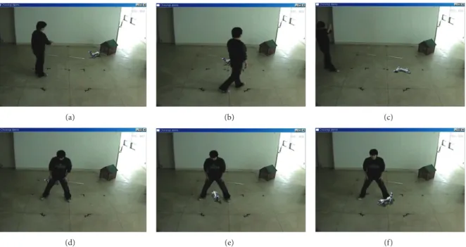
In the second application, to apply the proposed system, we employed it in a virtual pet system based on augmented reality. As shown inFigure 8, only a person and a dog’s house exist in a real environment. With the position of the calibrated object result and the human action recognition result, user can make a relationship with a virtual pet, called Cho-Rong-I. The ground of the real environment is calibrated in the initial stage so that the bottom-center coordinate of each object can be converted into the coordinate in the ground.
We made several complex scenarios in order to probe the performance of the proposed system as follows: Cho-Rong-I follows the owner in Figures8(a)and8(b)and pretends to die when the owner pretends to shoot inFigure 8(c). Figures
8(d)to8(f)show that Cho-Rong-I passes under the owner’s legs. As the proposed system obtained the precise position, the augmented dog, Cho-Rong-I, also reacts with the person at the virtual region matching the real coordinates.
6. Conclusion
In this paper, we proposed adaptive sensor fusion methods that compensate for horizontal bias between a laser scanner and video camera for tracking people in real-time system. The usual method using the checkerboard is inconvenient to track people simultaneously because of the manual calibration in a previous research. The proposed system in this paper over-comes the problem using an automatic adaptive sensor fusion method in real-time people tracking. In this application field, the accuracy of compensation is a significant factor for a
(a) (b) (c)
(d) (e) (f)
Figure 8: Demonstration of the virtual pet system.
real-time system. In order to match images between the video camera and laser scanner, we propose the algorithm to merge the laser scanner and video camera simultaneously by capturing the position of the candidate region and the cluster of the laser scan datum. To evaluate the performance of the proposed system, we employed it for tracking two people and then applied it in an augmented reality where one person can interact with a virtual pet. These results show that the proposed system can be successfully employed to obtain the peoples’ position by automatic sensor fusion. To enhance the proposed system, variations of the other axis should also be considered. We are currently improving our system to include the uncertainty variations of the sensor position.
Acknowledgments
This work was supported by the Basic Science Research Program through a Grant from the National Research Foun-dation of Korea (NRF) funded by the Ministry of Education, Science and Technology (2012-0005793 and 2011–0013776). This work was also supported by the IT R&D Program of MKE/KEIT “Development of learner-participatory and inter-active 3D virtual learning contents technology” (10039165) and the NAP (National Agenda Project) of Korea Research Council of Fundamental Science and Technology.
References
[1] J. Cui, H. Zha, H. Zhao, and R. Shibasaki, “Multi-modal tracking of people using laser scanners and video camera,” Image and
Vision Computing, vol. 26, no. 2, pp. 240–252, 2008.
[2] Y. Bok, Y. Hwang, and I. S. Kweon, “Accurate motion estimation and high-precision 3D reconstruction by sensor fusion,” in
Proceedings of the IEEE International Conference on Robotics and Automation (ICRA ’07), pp. 4721–4726, April 2007.
[3] Q. Zhang and R. Pless, “Extrinsic calibration of a camera and laser range finder (improves camera calibration),” in Proceedings
of the International Conference on Intelligent Robots and Systems (IROS ’04), pp. 2301–2306, October 2004.
[4] R. Y. Tsai, “A versatile camera calibration technique for high-accuracy 3D machine vision metrology using off-the-shelf TV cameras and lenses,” IEEE Journal of Robotics and Automation, vol. 3, no. 4, pp. 323–344, 1987.
[5] Z. Zhang, “Flexible camera calibration by viewing a plane from unknown orientations,” in Proceedings of the 7th IEEE
International Conference on Computer Vision (ICCV ’99), pp.
666–673, September 1999.
[6] C. Mei and P. Rives, “Calibration between a central catadioptric camera and a laser range finder for robotic applications,” in
Proceedings of the IEEE International Conference on Robotics and Automation (ICRA ’06), pp. 532–537, May 2006.
[7] C. Stauffer and W. E. L. Grimson, “Adaptive background mixture models for real-time tracking,” in Proceedings of the
IEEE Computer Society Conference on Computer Vision and Pattern Recognition (CVPR ’99), pp. 246–252, June 1999.
[8] Y. Tian, A. Senior, and M. Lu, “Robust and efficient foreground analysis in complex surveillance videos,” Machine Vision and
Applications, vol. 23, no. 5, pp. 967–983, 2012.
[9] J. Choi, Y. Cho, K. Cho, S. Bae, and H. Yang, “A view-based multiple objects tracking and human action recognition for interactive virtual environments,” International Journal of
Virtual Reality, vol. 5, no. 3, pp. 1–6, 2006.
[10] P. Ryan, “Count the steps to motivate walking,” Functional U, vol. 3, no. 3, pp. 12–16, 2005.
Submit your manuscripts at
http://www.hindawi.com
Control Science and Engineering Journal of
Hindawi Publishing Corporation
http://www.hindawi.com Volume 2013
Hindawi Publishing Corporation
http://www.hindawi.com Volume 2013Part I
VLSI Design
Hindawi Publishing Corporation
http://www.hindawi.com Volume 2013
ISRN
Signal Processing Hindawi Publishing Corporation
http://www.hindawi.com Volume 2013
Hindawi Publishing Corporation
http://www.hindawi.com Volume 2013 Mechanical Engineering Modelling & Simulation in Engineering Hindawi Publishing Corporation
http://www.hindawi.com Volume 2013
Advances in
Acoustics &
Vibration
Hindawi Publishing Corporation
http://www.hindawi.com Volume 2013
ISRN
Sensor Networks Hindawi Publishing Corporation
http://www.hindawi.com Volume 2013
Hindawi Publishing Corporation
http://www.hindawi.com Volume 2013
Electrical and Computer Engineering
Journal of
Hindawi Publishing Corporation
http://www.hindawi.com Volume 2013
Distributed
Sensor Networks
ISRN Robotics Hindawi Publishing Corporation
http://www.hindawi.com Volume 2013
International Journal of
Antennas and
Propagation
Hindawi Publishing Corporation
http://www.hindawi.com Volume 2013
ISRN Electronics Hindawi Publishing Corporation
http://www.hindawi.com Volume 2013
Advances in OptoElectronics
Hindawi Publishing Corporation
http://www.hindawi.com Volume 2013
Hindawi Publishing Corporation
http://www.hindawi.com Volume 2013
Hindawi Publishing Corporation
http://www.hindawi.com Volume 2013
The Scientific
World Journal
Hindawi Publishing Corporation
http://www.hindawi.com Volume 2013 Active and Passive Electronic Components
Chemical Engineering
International Journal of
Hindawi Publishing Corporation
http://www.hindawi.com Volume 2013
ISRN
Civil Engineering Hindawi Publishing Corporation
http://www.hindawi.com Volume 2013
Hindawi Publishing Corporation
http://www.hindawi.com Volume 2013
Journal of