Journal of International Conference on Electrical Machines and Systems vol. 3, no. 4, pp. 472~480, 2014 472
A Study on New PV Tracking System Including Load Dispersion
Sang-Hun Lee*, Hyun-Jig Song*, Chan-Gyu Park*, and Sung-Geon Song**
Abstract
– The In solar power system, the height and azimuth of the sun are important parameters which control generated power magnitude. The tracking method that controls the daily generation magnitude according to latitude and longitude using the two axles is often used in the existing sunlight tracking system today. In this two-axle PV track control system, the self-load is concentrated on one FRAME. It is influenced of the regular load, snow load and the wind load, etc. It is difficult to set up the system in the conventional building. This research is a development about the small-scale economy track device of independent load-dispersing solar generation system. The position tracking algorithm is through new coordinates transformation calculating the height and azimuth of the sun.Keywords:
Parallel switching operations, Current division1. Introduction
This In solar power generating system, a series of methods are generally being used to enhance generation efficiency: using solar cell with higher transformation efficiency, raising transformation efficiency of transformer, performing maximum power point tracking(MPPT), and having the sun incident on solar cell module, maintaining the normal all the time. Since the method of raising transformation efficiency of cell is a major cause to increase generation cost, it is lower in efficiency today. Also, it is very difficult to raise the efficiency of transformer as much as tens of percentages. Therefore, there is a growing interest in a PV tracking system which makes the sun incident on solar cell module, maintaining the normal all the time[8]-[10]. For the development and commercialization of a PV-based system, many studies including the structure of solar position tracking system, system efficiency by tracking method, variations of output according to the presence of solar position tracking system, development of solar position tracking sensor for a PV tracking system, and development of tracking algorithm for using a microprocessor have been made in relation to the development and commercialization of solar position tracking system[1]-[4].
In this study, a new method of solar position tracking system which makes the sun incident on solar cell module,
maintaining the normal all the time, was suggested for effective uses of solar cells in PV generating system. The solar tracking system sunflower series, which are widely being used today, are controlled by two axes one of which moves in a circle on the horizontal plane to control azimuth, which requires extensive driving displacement of the system during the solar position tracking. Moreover, in order to increase density in driving part, sunflower-type solar position tracking system needs additional security work to place it on the roof of a building in the way of making load concentrated on a single point, when installing solar cell array, with higher costs of installation. The study proposed an economical PV tracking device in a linear load PV system in an effort to reduce weaknesses of point-load based sunflower type solar position tracking device. The solar position tracking algorithm used in this study was transformed into a new coordinates by calculating the height and azimuth of the sun, for driving the proposed tracking system, and on the basis of transformed coordinates, DC motor system-based lifting was applied to height. As far as azimuth is concerned, linear movement by DC motor and locker arm changed into swing movement, so that solar module is placed horizontally with the plane of daily locus of the sun. For the proposed system, controlling methods and structure are explored to improve currently used programmed solar position tracking system, on the basis of various verified solar geometric theories.
2. Theories of Solar Position Tracking System
2.1 Comparison of PV output according to inclined plane
* Dept. of Automatic Electrical Engineering, Youngnam University College, Korea. ([email protected])
** Digital Convergence Research Center, KETI, Korea
In photovoltaic system, incident angle of solar power energy from the sun determines the capacity and efficiency of the system to a larger degree. This emphasizes that when using PV as a source of energy, it is highly important to calculate optimum tilt angle of light receiving surface because direct effect on the capacity of PV system greatly varies installation angle and direction.
Korea Institute of Energy Research analyzed PV energy on inclined plane in each direction for PV system design, on the basis of data measured hourly for 5 and a half years from August 1996 to February 2002 at Daejeon in which our institute is located. To measure direction-specific PV energy on inclined plane, 7 solar radiation sensors were installed to south direction at the calculation site, by converting in 15° interval between 0° and 90° of tilt angle to horizontal plane, with one for east, west, and north directions, respectively, at tilt angle 90°, which totals 10. Data acquired from the system installed as above was analyzed by remote control and gone through computer-based processing.
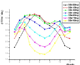
As shown in Fig. 1, condensing plane between 0° and 90° of tilt angle 30° to ground surface in south direction was found to have the maximum solar radiation. By season, as seen in Fig. 2, in winter when heating is used, solar radiation on vertical surface facing south was about 2.6 times more than vertical surface to east or west direction, 1.5 times more than on total solar light on horizontal plane, and 9 times PV on vertical surface facing north.
In summer, solar radiation on vertical surface in east and west direction, except for the north direction in summer and on vertical surface facing south in spring and autumn including that on north direction tended to be higher than that on vertical surface in east and west directions.
Fig. 1. Solar Power Energy according to month
Fig. 2. Solar Power Energy according to season
These results show that as vertical surface facing south receives maximum heat in winter, while receiving greatly less heat in summer, it is more effective in energy absorption to place the system not in south-north direction, but in east-west direction. In addition, seasonal characteristics of tilt angle in south direction are shown in Fig. 2: it is found that the maximum PV energy is measured on condensing plane at tilt angle 30° to ground surface in spring, at tilt angle 15° in summer, and at tilt angle 45° in autumn and winter. As discussed above, efficiency of PV system may vary by solar position tracking and capacity, as proved data show that radiation level is varied by inclined plane of horizontal surface. Namely, when using PV as a source of energy, overall capacity and efficiency of PV system greatly varies by incident angle of solar energy from the sun. This indicates that studies on how to improve the efficiency of PV system through cheaper and efficient solar position tracking system have been ceaselessly conducted for the purpose of making low density PV energy highly integrated at night or due to changes in natural environment including rain [6][7].
2.2 Calculation of Solar Position
As the output of a solar cell is proportional to incoming light intensity, the output is maximized when the solar cell is located in normal direction of PV under the same external environment. Like this, to make a solar cell place in normal direction of PV, it needs data on the location of the sun at current time. The earth moves around the sun by 1° in counter-clock wise everyday, while axis of rotation moves from west to east, tilting at 23.45°, which requires a bit complicated formula to calculate azimuth and height of the
sun. To calculate azimuth and height, time, it is necessary to calculate leap year, declination, equation of time, true solar time and solar hour angle, according to solar geometry. First of all, declination is the angle formed between the equator of the earth and light directly emitted from central axes of the earth and the sun, marked as
. It changes day by day by ±23.45° between two extremes, as revolution axis of the earth tilts at 23.45°, and accurate value of declination, which slightly changes every year in a simple sine curve on a 365 days a year basis is released annually in astro-calendar and almanac in USA. The Equation(1) can be shown as follow.360
23.45sin[
(
284)]
365
n
(1)Note, n=total number of man-days and conclusion.
Solar hour angle H is the angle between the time zone after passing the local meridian is installed with solar cell panel time zone, that is, it is the angle measured by moving westward from the south point. The angles measured westward after the sun moves past the meridian are converted into 15°= 1 hour, 15` = 1 minute, 15`` = 1 second, and marked hour(h), minute(m), and second(s), respectively, and the equation to calculate the angle is as shown in (2). Hour angle refers to elapsed hours after the sun crosses the meridian. In particular, the solar hour angle is equivalent to the time in the afternoon at the site of observation. In other words, solar time is the result of hour angle plus 12 hours.
(
12) 15
)
180
180 ,
( ),
( )
:
sol solHour angle H
T
note
H
morning
afternoon
T
true solar time
( 2 ) In Equation (2), some problem occurs when calculating azimuth of the sun. The azimuth of the sun in the early morning and late afternoon in spring and summer always maintains 90° or over from south. In addition, as sine value is varied as in conditions set forth in Equation(3) are needed to make the azimuth bigger or smaller than 90° from south.
tan
cos
,
90 ,
tan
90
S Sif
H
ture
L
failure
(3)To calculate solar time angle, it is needed to know true solar hour, which is obtained by Equation (4).
(
) /15
(
)
)
sol std std loc t std std locT
T
L
L
E hr
note T
local standard time
L
Longitude of land
L
Longitude of standard meridian
(4)
Here, to calculate solar time angle, equation of time is needed, which refers to time difference between true solar hour and mean solar hour occurring when the earth moves around the sun not in a circle but in a fixed oval-shaped orbit, as shown in Equation (5).
0.0002865sin 2 0.00713576 cos 0.12253414sin 0.0558293cos 2 0.1561998sin 2 [minute]
360 ) ( 1) [ ], 365 t E B B B B B note B n degrees
n total number of man days
(5)
Using the declination and time angle obtained by equation (1) and (2) above, elevation and azimuth on ground surface coordinates are as follows:
sin
cos cos cosh sin sin
L
L
(6)cos sin
sin
cos
SH
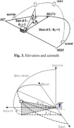
(7) As shown in Equation (6), positive(+) azimuth means afternoon, while negative(-) means morning.2.3 Coordinates of proposed solar position tracking system
In the existing sunflower-type solar position tracking system, altitude is at the level where the observer looks at the height of the sun from a point of horizontal plane. In addition, one axis to control azimuth moves horizontally on ground surface, which increases the variation in altitude, moving around the hourly tracking site, when tracking daily locus plane of the sun tilting at as much as altitude to horizontal plane. Therefore, in this study, a new coordinate was proposed to control one axis of solar position tracking system so that one axis to controlling azimuth is horizontal to daily locus surface of the sun. Fig. 4 shows a new coordinates calculation of proposed PV solar position tracking system using height and azimuth of the sun according to the current time.
Fig. 3. Elevation and azimuth Z e n i t h Ea s t S o u t h W e s t Φs Φh β s M e r i d i a n β h
Fig. 4. Vertical and horizontal axis angle of proposed solar
position tracker
In calculating azimuth, while existing solar position tracking system employs azimuth on ground surface, azimuth in proposed tracking system must be converted into the azimuth of locus surface tilting as much as the angle formed by ground surface and height of the sun. The function of existing height-azimuth of such converted height and azimuth is as shown in Equation (8) and (9).
1
tan [tan(
) / cos( )]
h s s
(8)
1tan [cos(
) cos( )]
h s s
(9)
2.4 Design of Solar Position Tracking System UsingProposed Coordinates
Fig. 5 shows a new vertical and horizontal axis PV tracker to reduce weaknesses of sunflower-type solar position tracking device, which are generally being used today. Altitude was controlled by rotation of vertical axis, which is a supporting frame to secure solar cell panel in the upper part, and azimuth was controlled by linear movement using DC motor and worm gear so that each solar module
can move in a circle, with locker arm being used to switch such linear movement into swing motion. Although this tracking device in which each solar cell module moves together by lock arm is strong to external disturbances such as wind power, lengths between solar cells are needed for each solar cell to track PV without interference. Therefore, this length determines tracking time.
Even though distance between solar cells should be longer to increase tracking time, broader space is needed for installation. Therefore, design of lengths between solar cells functions as a decisive element in determining tracking time. Fig. 6 explains the concept of PV tracking time according to solar cell width. Azimuth of the sun changes by 15° an hour, controllable maximum azimuth(
) is determined, once tracking time is set.Once the maximum azimuth is determined, length between solar cells is calculated by the following equation:
/ cos( )
w s
l
l
(10)(a) Overview
(b) Side view
Fig. 5. Solar position tracker of vertical and horizontal
Fig. 7 shows normalized length according to tracking angle for solar cell width. In this study, as a result of calculations done through a variety of experiments, PV tracking time was set as 8 hours, length between solar cells is as twice as the width of solar cell panel.
Fig. 6. Solar position tracking time according to cell-width
Fig. 7. Length according to maximum elevation
3. Simulation of Proposed Tracking System
In order to compare efficiency of existing sunflower-type position tracking system and proposed PV tracking system including load dispersion, coordinates locus for daily locus of the sun at point 4 in the orbit of revolution of the sun, computerized simulation was performed at the observation site at latitude 20° and longitude 127°, to examine movement locus of the two systems.
Fig. 8 shows tracking azimuth and daily locus of altitude during spring and autumnal equinox in existing sunflower-type tracking system and proposed load-dispersion system. As shown in this picture, altitude under existing system ranges between 0° and 50°, as time goes by, while there is almost no change of altitude in proposed system. Therefore, it is considered that power consumption to control altitude is strikingly lower than existing system, near spring or autumnal point. In addition, compared to existing system, variations of azimuth is uniform regardless of time, which makes total movement of the tracking
system smaller than existing system and thereby reduces power consumption in driving part of the tracking system, as one of the advantages of the system. Fig. 9 and 10 show the azimuth and altitude on winter and summer solstice. In Fig. 9, during winter solstice, azimuth and altitude of the two systems are almost identical. However, in winter solstice, since variation ratio of azimuth in proposed system is lower than existing one and driving part is run by constant force, which reduces power consumption of driving part for azimuth tracking control, and positive torque operation is possible.
The outcome of the simulation implies that in proposed system, variation of tracking daily locus in relation to daily azimuth is uniform regardless of season, while that of altitude increases in winter and summer solstice from spring and autumnal point. However, existing sunflower-type tracking system is identical in the pattern of altitude variations with proposed tracking system, with slightly bigger change than proposed tracking system. In terms of azimuth variations, proposed system moves in the same pattern of daily locus, regardless of seasonal changes, while existing sunflower-type tracking system was found to have a wide gap in variations of azimuth by season. Therefore, as shown in Fig.10, the system has almost identical variations of altitude with existing sunflower-type tracking system. Based on the results of above simulation, to make it easier to compare driving displacement of existing sunflower-type PV tracking system and proposed one, variations of daily locus for a year of the two systems were calculated. Using Matlab Program, Fig.11 compares simulations of total tracking daily locus for a year of driving part of existing sunflower-type PV tracking system and proposed one, with PV tracking system placed at latitude 36°and longitude 125°to track the sun.
As seen from the picture, existing tracking system shows a sine-shaped variation of daily altitude. In proposed tracking system, variations of daily altitude between winter solstice and spring equinox and between autumnal equinox and winter solstice are uniform, showing symmetric curve in which variation level is maximized from spring equinox toward summer solstice and decreasing again toward autumnal equinox. The azimuth in existing tracking system shows a sine-shaped variation as altitude does, while that in proposed tracking system shows a change of daily variation ratio from spring and autumnal point toward winter solstice, and daily variation ratio becomes uniform as the sun goes closer to summer solstice, with a wide gap in variation.
As shown in the picture, when adding up variations of these two coordinates, compared to existing tracking system, total variation of proposed tracking system is smaller, with lower variation ratio.
Fig. 8. Comparison of elevation azimuth spring & autumnal
Fig. 9. Comparison of elevation and azimuth on winter
solstice.
Fig. 10. Comparison of elevation and azimuth on summer
solstice. 0 50 100 150 200 250 300 350 400 60 80 100 120 140 160 180 200 220 Conventional Proposed Day of Year A z im u th ( a n g le )
(a) Comparison of variation of year's azimuth
Conventional Proposed 0 50 100 150 200 250 300 350 400 0 10 20 30 40 50 60 A lt it u d e ( a n g le ) Day of Year (b) Comparison of variation of year's altitude
T o ta l m o v e m e n t ( a n g le ) Day of Year Conventional Proposed 0 50 100 150 200 250 300 350 400 60 80 100 120 140 160 180 200 220 240 260 280
(c) Comparison of year's total variations
Fig. 11. Variation of year's locus for each tracking system.
45° 37° 35° 30° 27° 25° 40° 32° Day of year T o ta l m o v e m e n t( a n g le ) -50 0 50 100 150 200 250 300 350 400 20 40 60 80 100 120 140 160 180 200 220 240 260 280 300
(a) Year's movements of existing system
-50 0 50 100 150 200 250 300 350 400 20 30 40 50 60 70 80 90 100 110 120 130 140 150 160 170 180 190 200 T o ta l m o v e m e n t( a n g le ) Day of year 45° 37° 35° 30° 27° 25° 40° 32°
(b) Year's movements of proposed system
Fig. 12. Variation of year's locus for each tracking system
Results of the simulation as shown in Fig. 11 indicate that compared to existing sunflower-type tracking system, proposed tracking system is more effective in tracking, which helps overall efficiency of PV generation by saving power consumed in driving part. Fig. 12 shows total year’s driving locus adding up azimuth and altitude locus. In year’s driving locus, proposed PV tracking system is smaller than existing sunflower tracking system, regardless of latitude. In relation to the variation of year’s driving locus according to latitude, both existing tracking system and proposed tracking system have a lot of driving movements, as total driving locus is bigger at lower latitudes.
Results of the simulation as shown in Fig. 11 indicate that compared to existing sunflower-type tracking system, proposed tracking system is more effective in tracking, which helps overall efficiency of PV generation by saving power consumed in driving part. Fig. 12 shows total year’s driving locus adding up azimuth and altitude locus. In year’s driving locus, proposed PV tracking system is smaller than existing sunflower tracking system, regardless of latitude. In relation to the variation of year’s driving locus according to latitude, both existing tracking system and proposed tracking system have a lot of driving movements, as total driving locus is bigger at lower latitudes.
4. Analysis of Characteristics of Proposed Tracking
System
Fig. 13 shows 120[W]-grade PV tracking system used in this study. Structurally, the PV tracking system has an H frame-shaped stand to fix and support the solar cell panel, 2 sets of DC motors for vertical and horizontal axis to drive the solar cell at one axis of the frame inside of which a control board to control the PV tracking system is installed.
Fig. 13. Proposed solar tracking system.
A small DC motor with a built-in gear for windows of 12V vehicles was used for the driving device, and DSP TMS320LF2406A was employed as a with controlling microprocessor, with a key to determine the state of the operation and LCD to display various information. For the purpose of evaluating the capacity of proposed PV tracking system, hourly output of fixing, existing sunflower-type and proposed tracking system is compared. Hourly observation of generation data of a PV tracking system needs a PV tracking system and a PC-based monitoring system. In Fig. 14, outputs of proposed tracking system and fixing system on a sunny day with slight clouds are compared.
Fig. 14. The output comparison of tracking and fixing
system.
Fig. 15. The output comparison of tracking and fixing
system.(Sunny day)
Fig. 16. The output comparison of tracking and fixing
In overall time zone, except between 12 and 1 during which the sun crosses the meridian, output of tracking system was found higher. Data of outputs from proposed tracking system and sunflower-type tracking system on a sunny day with almost no clouds is compared in Fig. 15. From 9 a.m. when the generation starts, proposed system and sunflower-type device produce far more output than the fixing type. For one and a half hours before and after the sun crosses the meridian, fixing and tracking systems are almost similar in output. There is no big difference in output between the sunflower-type and proposed PV tracking system. Fig. 16 above compares output of a day when it was clear in the morning and after 2 pm became heavily cloudy. In the afternoon when it was heavily cloudy, there were many obstacles by the movements of clouds, which resulted in sharp decrease in output, with a wide gap.
5. Conclusion
In this study, new tracking coordinates are proposed, which is to raise the efficiency of driving part of solar position tracking system by calculating daily locus of the sun with a program, among other PV solar position tracking system designed to increase output of solar cells. A simulation method was employed in the comparison with existing sunflower system. As a result of the simulation, compared to existing sunflower type, daily driving displacement of proposed PV tracking system was smaller, being smaller as well in the comparison of year’s driving displacement adding up daily driving displacements. Variation in driving displacement of both tracking systems according to the place of installation has no connection with longitudes and latitudes of installation place, while driving displacement resulted in differently according to latitude. In regard to the variation of altitude of both tracking systems at lower latitudes, the driving displacement around summer solstice of proposed solar position tracking system is bigger than existing sunflower-type position tracker. However, as far as total driving displacement was concerned, proposed solar position tracking system is always lower than the existing sunflower-type position tracker. On the basis of such simulation results, a PV tracking system in proposed method was designed and manufactured and output efficiency with fixing and sunflower-type tracking system was compared, analyzed and experimented. As a result of experiments on output using the fixed type, the difference proposed system, compared to the fixed type. In overall time zone, except 1 hour or so, before and after the sun crosses the meridian, the tracking system was found to achieve even higher output efficiency Moreover, also in
comparison of output with the point-load based sunflower-type, the result showed that it generated the equal output, despite lower driving displacement.
References
[1] R. Zogbi and D. Laplaze, "Design and construction of a sun tracker", Solar Energy, Vol. 33, No. 3/4, pp. 369-372, 1984. [2] P. Baltas, M. Tortoreli and P.E. Russell, "Evaluation of power
output for the fixed and step tracking photovoltaic arrays", Solar Energy, Vol. 37. No. 2, pp.147-163, 1986.
[3] D. M. Mosher, R. E. Blese and R. J. Soukupt, " The advantage of suntracking for planar silicon solar cells", Solar Energy, Vol. 19, pp. 91-97, 1977.
[4] A. Konar and A.K. Mandal, "Microprocessor based automatic sun tracker", IEE Proceedings-A, Vol. 138, No. 4, pp. 237-241, 1991.
[5] W. A. Lynch and Z. M. Salameh, " Simple electro-optically controlled dual- axie sun tracker", Solar Energy Vol. 45. No. 2, pp. 65-69, 1990.
[6] Choi Deuk Gi, Kang Yong Deuk, Lee Eui Joon, and Oh Jeong Moo, “A Study on Optimum Installation of PV Generation System in Korea”, Journal of the Korean Solar Energy Society Vol. 24, No. 3, 2004.
[7] Choi Deuk Gi, Kang Yong Hyeok, and Oh Jeong Moo, “A Study on the Analysis of Usability of Solar Energy in the Korean Peninsular Using Satellites”, Journal of the Korean Solar Energy Society Vol. 22, No. 3, 2002.
[8] Kim Gi Beum, Lee Kang Yeon, Park Jeong Min, Park Jin Yeong, Baek Hyung Lae, and Choi Geum Bae, “A Study on Generation Efficiency according to Incident Angle of a Connected PV Generation System”, Collection of Power and Electronics Conference, pp. 42 ~ 44, 7, 2002.
[9] Lee Yang Gyu, Kang Shin Young, and Kim Kwang Heon, “Development of Program-Type Solar Position Tracker for Commercialization of Small-scaled PV Generation System”, Journal of Power and Electronics Society, Vol. 8, No. 3, pp. 260 ~ 265, 6, 2003.
[10] Lim Hee Cheon and Ahn Gyo Sang, “Technological Trends of Photovoltaic Generation”, Journal of Power and Electronics Society, Vol. 8, No. 3, pp. 27 ~ 34, 6, 2003
Sang-Hun Lee was born in Busan,
Korea, in 1974. He received his B.S and M.S. degrees in Electrical Engineering from Kyungsung University, Busan, Korea, in 2000, 2002, respectively. He received his Ph.D degrees in Mechatronics Engineering from Pusan National University, Busan, Korea, in 2006. He worked a Junior Researcher of Technology& Researcher at KTE, from 2002 to 2004, He has been with Kyungsung University, Busan, Korea, as a Researcher in the Advanced Electric Machinery & Electronics Center since 2006. Since 2014, he has been a Assistant Professor with the Department of Electrical Automatic Engineering, Yeungnam College of Science & Technology, Daegu, Korea. His major research field is Electrical Motor Drive with Power Electronics.
Hyun Jig Song was born in Deagu,
Korea, in 1968. He received the B.S., M.S. and Ph.D degrees in electrical engineering from Yeungnam University, in 1991, 1993 and 1997, respectively. Since 2006, He has been an Associate Professor with the Department of Electrical Automatic Engineering, Yeungnam College of Science & Technology, Daegu, Korea. His current research interests include High-voltage Engineering, Electric power system and power electronics.
Chan-Gyu Park was born in Deagu,
Korea, in 1959. He received the B.S. degrees in electrical engineering from Kyungil University, in 1987. He received the M.S. and Ph.D degrees in electrical engineering from Yeungnam University, in 1991 and 2000, respectively. Since 1995, He has been a Professor with the Department of Electrical Automatic Engineering, Yeungnam College of Science & Technology, Daegu, Korea. His current research interests include Automatic control Engineering, Digital control system and power electronics
Song Sung Geun was born in
Gwang-Ju, Korea. He received the B.S., M.S. and Ph.D degrees in electrical engineering from Chonnam National University, in 1998, 2000 and 2007, respectively. From 2001 to 2004, he was a Research Scientist at PROCOM system, Ltd., From 2004 to 2005, he was a Research Scientist at SEO ELECTRONICS CO., LTD. Since 2008, he is working in KETI(Korea Electronics Technology Institute), where he is currently Gwang-Ju Regional Headquarter. His fields of interest are power electronics, motor drives, digital signal processing, tractions, and their control system.