Flow Behavior Analysis of the Inlet Plenum with Narrow Type Flow-skirt
using CFD code
Jong-hark Parkj, Hee-taek Chae, Cheol Park, Heon-il Kim, Jun-hong Kim
Korea Atomic Energy Research Institute, Dukjin-dong 150, Yuseong, Daejeon, Korea HANARO Management Div., Research Reactor Analysis Dept., [email protected]
1. Introduction
Application of a flow-skirt to the conceptual design of a new research reactor has been considered to reduce the flow induced vibration of fuel assembly. CFD analysis shows that the flow-skirt may suppress the vortex generation at the inlet plenum, which is expected to contribute a lot in decreasing the vibration of the fuel assembly. Because the flow skirt considered from the previous research[1] was large in diameter and the holes were concentrated on lower side of flow skirt, it lead to have large space, the vortices rotating on the vertical direction occured. To complement like this weak point, CFX analysis has been performed to find out flow characteristic from the inlet plenum equipped with the narrow type flow-skirt.
2. Computational model
Fig. 1 shows perspective views of inlet plenum equipped with two different narrow type flow-skirts. There are 540 holes of diameter 26.4mm at lower side of the flow skirt, which are arranged in 18×30. Twenty-three flow tubes of 50mm in diameter are located on the upper side of inlet plenum. Two types of the inlet plenum with different location of inlet are considered. As the inlet plenum type-I injects the cooling water directly through perforated region of flow skirt, the flow rate passing through the flow skirt is uneven due to the local difference of dynamic pressure. The type-II, the inlet location is moved to upper part where the skirt has smooth surface. Then, the bumping of injection water to flow skirt converts fairly the dynamic pressure to static pressure.
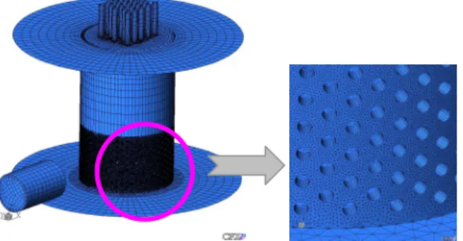
An unstructured mesh for calculation is shown in Fig. 2. The flow-skirt can be treated as a porous media in computational model, but it cannot simulate the effect of flow-skirt, except pressure drop, which has many holes to suppress
(a) type-I (b) type-II Fig. 1 perspective views of narrow-skirt inlet plenum
Fig. 2 Computation mesh
the vortex occurrence and reduce the pressure fluctuation. Every hole in the flow-skirt has been modeled with appropriate mesh in the calculation. Computational mesh consists of hexahedron, tetrahedron, pyramid and wedge. A total mesh number is about 1.6 million. The commercial CFD code, CFX-5.7, is used to solve computational model. The numerical advection correction scheme applied in convection term for discretization and RNG k-ε turbulent model known to suitable to the swirl flow is employed. Inlet boundary condition is specified as mass flow rate of 471.5kg/s corresponding to the average velocity reaches 8m/s at each flow tube. Opening condition of 0 Pa is given as boundary conditions of outlets of twenty-three flow tubes.
3. Results and discussions
The injected cooling water has high dynamic pressure due to high flow velocity. When the cooling water directly runs into the perforated region of flow-skirt (see Fig. 1 (a)), each hole of flow-flow-skirt has a different flow-rate with dynamic pressure distribution as shown in Fig. 3 (a), which may causes uneven velocity distribution near the entrance region of flow
(a) type-I (b) type-II Fig. 3 Dynamic pressure contours on the flow-skirt
Transactions of the Korean Nuclear Society Autumn Meeting Busan, Korea, October 27-28, 2005
(a) type-I (b) type-II
Fig. 4 Velocity contours near the entrance region of flow tube
tubes as shown in Fig. 4(a). The flow rate on each tube of manifold is strongly dependent on the dynamic head across the tube entrance region[2]. Such a uneven velocity distribution nearby tube entrance would lead to the mal-distribution flow rate in each flow tube.
In order to solve this problem, type-II is considered in such away that inlet is moved to upper side of the flow skirt where it has no holes. High velocity injection flow bumps against the no-hole region of flow-skirt, which change dynamic pressure to static pressure. Figure 3(b) shows that dynamic pressure near the perforated region of flow-skirt is relatively low and is distributed evenly, which leads to more uniform velocity distribution near the tube entrance region as shown in Fig. 4(b).
The effect of the inlet location can be shown in Fig. 5. The velocity contours of type-I are distorted for all flow tubes, which means that there may exist small strong vortices affecting pressure fluctuation. But type-II shows centralizing and relatively even distribution of flows.
(a) type-I (b) type-II Fig. 5 Velocity contours in outlet of each flow tubes
4. Conclusions
To get more uniform flow distribution by suppressing vortex generation and pressure fluctuation, two narrow type flow-skirts are proposed and studied their effectiveness by CFD analysis.
According to the CFD analysis results, inlet should be located far from the perforated region of flow-skirt to avoid direct bumping into the holes of flow-skirt. Narrow type flow-skirt can make flow rate of each tube more even than the wide type one considered in the previous study[1].
From this discussions, newly revised narrow type flow-skirt will be proposed.
[1] J. H Park, H. T. Chae, C. Park and H. Kim, Flow Behaviors in a Lower Plenum with Flow Skirt and Flow Straightener, 6th International Topical Meeting on Nuclear Reactor Thermal Hydraulics, Operation and Safety (NUTHOS-6), Oct. 4-8, 2004, Nara, Japan [2] Heat Exchanger Design Handbook Section II : Fluid Mechanics and Heat Transfer, pp. 89-94. Hemisphere Pub. Co. 1983.