Research Article
MIMO Antenna with High Isolation for WBAN Applications
Do-Gu Kang, Jinpil Tak, and Jaehoon Choi
Department of Electronics and Communications Engineering, Hanyang University, 222 Wangsimni-ro, Seongdong-gu, Seoul 133-791, Republic of Korea
Correspondence should be addressed to Jaehoon Choi; [email protected] Received 18 September 2014; Revised 23 December 2014; Accepted 4 February 2015 Academic Editor: Yuan Yao
Copyright © 2015 Do-Gu Kang et al. This is an open access article distributed under the Creative Commons Attribution License, which permits unrestricted use, distribution, and reproduction in any medium, provided the original work is properly cited. A multi-input multi-output (MIMO) antenna with high isolation is proposed for 2.4 GHz ISM band (2.4–2.485 GHz) WBAN applications. The proposed MIMO antenna consists of two PIFA elements and utilizes an isolator composed of a shorted strip
and two slits in the ground plane. Although the separation between the two PIFAs is minimized to 8 mm (0.06𝜆∘), isolation
performance is improved by virtue of an isolator. To analyze the antenna’s performance on a human body, the proposed antenna
is placed on a human muscle-equivalent flat phantom and is investigated through simulations. The measured−10 dB reflection
coefficient bandwidth of the antenna ranges from 2.11 GHz to 2.6 GHz, and the isolation is lower than−38 dB over the 2.4 GHz ISM
band.
1. Introduction
Given the fast progress of wireless communication tech-nologies, wireless body area network (WBAN) systems have received considerable attention for various applications [1,2]. Because WBAN systems can be placed on or in the human body with high permittivity and conductivity at microwave frequencies, the gain and efficiency of an antenna for WBAN systems can be degraded [3–6]. Furthermore, to operate in WBAN communication environment, the antenna should have compact size, low height, insensitiveness to human body effects, and low specific absorption rate (SAR) [7].
Many researchers have conducted various studies on the performance analysis of on-body WBAN communication systems in the industrial, scientific, and medical (ISM) bands [8–11]. Because of reflections/scatterings that occur in a neighborhood environment and/or on the human body, severe multipath fading can arise in on-body communication links [9]. Multipath fading not only decreases the com-munication reliability of multisignals but also worsens the efficiency of a WBAN system [12]. To improve communica-tion performance under the influence of multipath fading, a diversity technique such as input and multiple-output (MIMO) is necessary. Since the independence of the multisignals can be improved by the high isolation of
a MIMO antenna, a MIMO technique is frequently used to overcome the deterioration of communication performance due to multipath fading [13].
To achieve high isolation between MIMO antenna ele-ments, an isolator has been used by many researchers [14–
17]. A MIMO antenna with a high isolation characteristic is proposed by using a shorted strip and two slits in the ground plane [17]. The antenna has isolation lower than −32 dB for on-body WBAN applications in the 2.4 GHz ISM band. The MIMO antenna utilizes two planar inverted-F antenna (PIFA) elements with lengths of𝜆/4 at a resonant frequency to achieve a compact size [18]. The performance of the proposed antenna on the human muscle-equivalent flat phantom is analyzed by examining data such as the 𝑆-parameter characteristic, current distribution, radiation pattern, SAR, and envelope correlation coefficient (ECC).
2. Antenna Design and Analysis
2.1. Basic Geometry. The proposed MIMO antenna consists of two PIFAs, a shorted strip, and two slits in a ground plane, as shown in Figure1. The shorted strip, along with the two slits, acts as an isolator. The PIFAs, which have dimensions of 12× 10.5 × 2 mm3, are located on a FR4 substrate (𝜀𝑟 = 4.4) with a 1 mm thickness and an area of 40× 40 mm2. The two
Volume 2015, Article ID 370763, 7 pages http://dx.doi.org/10.1155/2015/370763
PIFA 1 PIFA 2 Port 1 Port 2 Short Short Ground plane Unit: mm 40 28.5 Shorted strip 3.75 0.5 z x y FR4 substrate 0.5 Slit 11.5 with1 mm thickness l2 (a) Bending line 4 A B 7 2 12 4 8.5 0.5 3.5 1 2 AB= radiator, length= l1 (b)
Figure 1: Geometry of the proposed antenna: (a) top view; (b) PIFA.
xy
z
200
Proposed 10
Human muscle-equivalent flat phantom
270 60
Unit: mm
antenna
(𝜀r= 52.7, 𝜎 = 1.95 S/m)
Figure 2: Proposed antenna on the phantom for simulation setup.
PIFAs are symmetrically placed with a separation distance of 8 mm (0.06𝜆∘) in the𝑦-axis direction. The isolator and the ground plane are printed on the upper side of the substrate.
To consider the effects on the human body, the simulation setup of an antenna on a human muscle-equivalent flat phantom is illustrated in Figure 2. The phantom, with a volume of 200× 270 × 60 mm3, has the relative dielectric constant (𝜀𝑟 = 52.7) and the conductivity (𝜎 = 1.95 S/m)
of human tissue [19]. Considering practical applications such as wearable Bluetooth services, the antenna is placed on the phantom with a separation distance of 10 mm to satisfy the required clearance to assemble the cover [3]. The antenna geometry was designed and analyzed by utilizing the high frequency structure simulator (HFSS 14) [20].
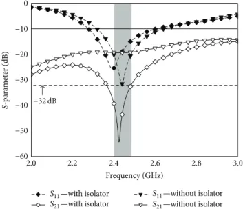
The simulated 𝑆-parameter characteristics of the pro-posed antenna with and without the isolator are compared in Figure3. The optimized design parameters are𝑙1 = 27.5 mm and 𝑙2 = 15.5 mm. The proposed antenna has a −10 dB reflection coefficient bandwidth ranging from 2.27 GHz to 2.6 GHz, which fully covers the desired 2.4 GHz ISM band. When the isolator is added between the two PIFAs, the isolation is improved significantly with a slight shift of the resonant frequency. The antenna has isolation below−32 dB in the 2.4 GHz ISM band.
To investigate the effect of the isolator, the simulated current distributions with and without the isolator at 2.4 GHz
2.0 2.2 2.4 2.6 2.8 3.0 −60 −50 −40 −30 −20 −10 0 Frequency (GHz) S-pa ra m et er (dB) −32 dB S11—with isolator S21—with isolator S11—without isolator S21—without isolator
Figure 3: Simulated𝑆-parameter characteristics for the proposed
antenna with and without isolator.
are shown in Figure4. By exciting port 1, substantial current is induced at PIFA 2 in the absence of the isolator. After the isolator is added, the induced current on PIFA 2 becomes weak. This is because the impedance of the 𝜆/4 isolator becomes large at 2.4 GHz so that the current flowing from port 1 to PIFA 2 is blocked by the isolator [21,22].
2.2. Key Parameter Analysis. The 𝑆-parameters of the pro-posed antenna with respect to a variation in the length (𝑙1) of the PIFA radiator are shown in Figure5. As𝑙1decreases, the resonance frequency shifts toward a higher frequency, while the isolation is improved. However, as 𝑙1 decreases beyond 27.5 mm, the isolation deteriorates. When 𝑙1 = 27.5 mm, the antenna satisfies the 2.4 GHz ISM band with optimum isolation.
Port 1 Port 2 PIFA 1 PIFA 2 Port 1 Port 2 PIFA 1 PIFA 2 Jsur f (A/m) 4.6431e + 001 4.2863e + 001 3.9294e + 001 3.5725e + 001 3.2157e + 001 2.8588e + 001 2.5020e + 001 2.1451e + 001 1.7882e + 001 1.4314e + 001 1.0745e + 001 7.1764e + 000 3.6078e + 000 3.9124e − 002 5.0000e + 001 (a) (b)
Figure 4: Simulated current distributions for the proposed antenna at 2.4 GHz (port 1: on, port 2: off): (a) without isolator; (b) with isolator.
2.0 2.2 2.4 2.6 2.8 3.0 −60 −50 −40 −20 −10 0 Frequency (GHz) S-pa ra m et er (dB) −30 −32 dB S11(l1= 23.5 mm) S21(l1= 23.5 mm) S11(l1= 25.5 mm) S21(l1= 25.5 mm) S11(l1= 27.5 mm) S21(l1= 27.5 mm) S11(l1= 29.5 mm) S21(l1= 29.5 mm) S11(l1= 31.5 mm) S21(l1= 31.5 mm)
Figure 5: Simulated𝑆-parameters for various values of length 𝑙1(𝑙2= 15.5 mm).
2.0 2.2 2.4 2.6 2.8 3.0 0 Frequency (GHz) −60 −50 −40 −20 −10 S-pa ra m et er (dB) −30 −32 dB S11(l2= 13.5 mm) S21(l2= 13.5 mm) S11(l2= 14.5 mm) S21(l2= 14.5 mm) S11(l2= 15.5 mm) S21(l2= 15.5 mm) S11(l2= 16.5 mm) S21(l2= 16.5 mm) S11(l2= 17.5 mm) S21(l2= 17.5 mm)
(a)
10 mm thickness spacer
𝜀r= 52.1
𝜎 = 0.94 S/m
(b)
Figure 7: Fabricated antenna and measurement setup. (a) Fabricated antenna; (b) the antenna on the phantom for measurement setup.
Table 1: Measured peak gain and radiation efficiency.
2.4 GHz PIFA 1 PIFA 2
Peak gain (dBi) 0.54 0.59
Efficiency (%) 21.34 21.37
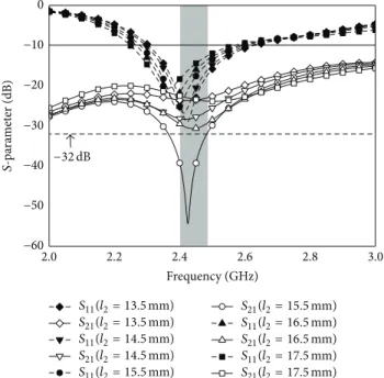
In Figure 6, the𝑆-parameters of the proposed antenna with respect to the various lengths (𝑙2) of the shorted strip are illustrated. A variation in𝑙2also changes the slit’s length because the tip of the shorted strip is fixed. As𝑙2increases, the isolation performance is improved and good impedance matching is obtained. However, after𝑙2 = 15.5 mm, the iso-lation degrades. To achieve optimum isoiso-lation performance, 𝑙2= 15.5 mm is chosen.
3. Antenna Performance
Photographs of the fabricated antenna and the human muscle-equivalent flat phantom for the measurement setup are shown in Figure 7 [23]. By utilizing the fabricated phantom (𝜀𝑟 = 52.1 and 𝜎 = 0.94 S/m), the performance of
the antenna on the human body can be investigated. The simulated and measured𝑆-parameter characteristics of the proposed antenna are compared in Figure 8. The measured and simulated results are in reasonably good agree-ment. The measured−10 dB reflection coefficient bandwidth of the fabricated antenna is 490 MHz from 2.11 GHz to 2.6 GHz, which satisfies the entire 2.4 GHz ISM band. The fabricated antenna has a measured isolation below−38 dB in the 2.4 GHz ISM band.
To analyze the effects on the human body when the proposed antenna operates, the SAR value of the antenna is calculated at 2.4 GHz, as shown in Figure9. The Federal Communications Commission (FCC) of the United States requires that the SAR be lower than 1.6 W/kg over a volume of 1 g of tissue [24]. The antenna has a SAR of 1.52 W/kg when an input power of 100 mW is applied. Thus, the proposed antenna can be used for low power Bluetooth device applications [25].
The simulated and measured far-field radiation patterns of the proposed antenna on the phantom are compared at
2.0 2.2 2.4 2.6 2.8 3.0 0 Frequency (GHz) −60 −50 −40 −20 −10 S-pa ra m et er (dB) −30 −38 dB S11-simulation S21-simulation S11-measurement S21-measurement
Figure 8: Simulated and measured 𝑆-parameter results for the
proposed antenna on the human muscle-equivalent flat phantom.
1.5178e + 000 1.4229e + 000 1.3281e + 000 1.2332e + 000 1.1384e + 000 1.0435e + 000 9.4864e−001 8.5378e−001 7.5892e−001 6.6406e−001 5.6920e−001 4.7434e−001 3.7947e−001 2.8461e−001 1.8975e−001 9.4892e−002 3.1256e−005 SAR field (W/kg)
Figure 9: Simulated SAR distribution of the proposed antenna on the phantom at 2.4 GHz (input power: 100 mW).
−50 −40 −30 −20 −10 00 30 60 90 120 150 180 210 240 270 300 330 −60 −50 −40 −30 −20 −10 0 PIFA 1 PIFA 2 −50 −40 −30 −20 −10 00 30 60 90 120 150 180 210 240 270 300 330 −60 −50 −40 −30 −20 −10 0 (a) Simulation Measurement Simulation Measurement PIFA 2 PIFA 1 −50 −40 −30 −20 −10 00 30 60 90 120 150 180 210 240 270 300 330 −60 −50 −40 −30 −20 −10 0 −50 −40 −30 −20 −10 00 30 60 90 120 150 180 210 240 270 300 330 −60 −50 −40 −30 −20 −10 0 (b)
Figure 10: Simulated and measured radiation patterns of the proposed antenna at 2.4 GHz. (a)𝑥𝑦 plane; (b) 𝑦𝑧 plane (𝜎 for simulation:
1.95 S/m,𝜎 for measurement: 0.94 S/m).
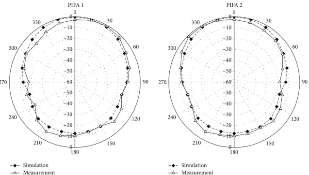
2.4 GHz, as shown in Figure10. The simulated and measured radiation patterns agree very well, except for those in the back radiation direction (150∘ ≤ 𝜃 ≤ 210∘) of the 𝑦𝑧
plane. The difference between the simulated and measured radiation patterns of the𝑦𝑧 plane occurs because the phan-tom has different conductivity values (conductivity for sim-ulation: 1.95 S/m, conductivity for measurement: 0.94 S/m). Because the radiated field reflected by the phantom with high conductivity used in the simulation is stronger than that of the measurement, the backward radiation decreases. When the conductivity for the simulation becomes 0.94 S/m,
the simulated radiation patterns are almost the same as the measured ones, as shown in Figure11. The radiation patterns of PIFA 1 are somewhat analogous to those of PIFA 2. The antenna has quasi-omnidirectional radiation patterns in the 𝑥𝑦 plane and has its peak radiation in the outward normal to the phantom surface in the𝑦𝑧 plane.
Measured radiation characteristics of the two PIFAs at 2.4 GHz are compared in Table1. The efficiencies of PIFA 1 and PIFA 2 are 21.34% and 21.37%, respectively.
The envelope correlation coefficient (ECC) is commonly utilized to evaluate the diversity capability of a MIMO
Simulation Measurement Simulation Measurement PIFA 2 PIFA 1 −50 −40 −30 −20 −10 00 30 60 90 120 150 180 210 240 270 300 330 −60 −50 −40 −30 −20 −10 0 −50 −40 −30 −20 −10 00 30 60 90 120 150 180 210 240 270 300 330 −60 −50 −40 −30 −20 −10 0
Figure 11: Simulated and measured radiation patterns (𝑦𝑧 plane) of the proposed antenna at 2.4 GHz (𝜎 for simulation and measurement: 0.94 S/m). 2.40 2.42 2.44 2.46 2.48 2.50 0.0 0.1 0.2 0.3 0.4 En ve lo p e co rr ela tio n co efficien t Frequency (GHz) Proposed antenna simulation Proposed antenna measurement Without isolator simulation
Figure 12: Simulated and measured envelope correlation coefficients of the proposed antenna with and without isolator.
antenna system. The ECC must be computed by using three-dimensional radiation patterns [26]. ECCs computed by simulated radiation patterns and measured radiation patterns are shown in Figure 12. The measured ECC agrees very well with the simulated one. The proposed antenna has an ECC value that is lower than 0.5 in the 2.4 GHz ISM band. When the computed ECCs with and without the isolator are compared, ECC performance improves owing to the improved isolation between PIFA 1 and PIFA 2.
4. Conclusion
A high isolation MIMO antenna is designed to operate in the 2.4 GHz ISM band for WBAN applications. When installed on a human muscle-equivalent flat phantom, the antenna satisfies the−10 dB reflection coefficient bandwidth of the 2.4 GHz ISM band. An isolator, consisting of a shorted strip and two slits, is added between the two PIFAs to improve the isolation. Although the two PIFAs are placed close to
each other with a separation distance of only 8 mm (0.06 𝜆∘), the antenna exhibits an isolation lower than −38 dB in the 2.4 GHz ISM band. Therefore, the above-mentioned properties prove that the proposed antenna is suitable for WBAN applications.
Conflict of Interests
The authors declare that there is no conflict of interests regarding the publication of this paper.
Acknowledgment
This research was partially supported by the MSIP (Ministry of Science, ICT and Future Planning), Korea, under the ITRC (Information Technology Research Center) support program (NIPA-2014-H0301-14-1017) supervised by the NIPA (National IT Industry Promotion Agency).
References
[1] T. Zasowski, F. Althaus, M. Stager, A. Wittneben, and G. Troster, “UWB for noninvasive wireless body area networks: channel measurements and results,” in Proceedings of the IEEE
Confer-ence on Ultra Wideband Systems and Technologies (UWBST ’03),
pp. 285–289, November 2003.
[2] P. S. Hall and Y. Hao, Antennas and Propagation for
Body-Centric Wireless Communications, Artech House, Norwood,
Mass, USA, 2006.
[3] M. U. Rehman, Y. Gao, Z. Wang et al., “Investigation
of on-body bluetooth transmission,” IET Microwaves,
Antennas and Propagation, vol. 4, no. 7, Article ID
IMAPCH000004000007000871000001, pp. 871–880, 2010. [4] C.-P. Deng, X.-Y. Liu, Z.-K. Zhang, and M. M. Tentzeris,
“A miniascape-like triple-band monopole antenna for WBAN applications,” IEEE Antennas and Wireless Propagation Letters, vol. 11, pp. 1330–1333, 2012.
[5] Z. N. Chen, A. Cai, T. S. P. See, X. Qing, and M. Y. W. Chia, “Small planar UWB antennas in proximity of the human head,”
IEEE Transactions on Microwave Theory and Techniques, vol. 54,
no. 4, pp. 1846–1856, 2006.
[6] P. S. Hall, Y. Hao, Y. I. Nechayev et al., “Antennas and propaga-tion for on-body communicapropaga-tion systems,” IEEE Antennas and
Propagation Magazine, vol. 49, no. 3, pp. 41–58, 2007.
[7] N. Haga, K. Saito, M. Takahashi, and K. Ito, “Characteristics of cavity slot antenna for body-area networks,” IEEE Transactions
on Antennas and Propagation, vol. 57, no. 4, pp. 837–843, 2009.
[8] J. Tak, K. Kwon, S. Kim, and J. Choi, “Dual-band on-body repeater antenna for in-on-on WBAN applications,”
Interna-tional Journal of Antennas and Propagation, vol. 2013, Article ID
107251, 12 pages, 2013.
[9] A. A. Serra, P. Nepa, G. Manara, and P. S. Hall, “Diversity for body area networks,” in Proceedings of the 29th URSI General
Assembly, pp. 1–4, Chicago, Ill, USA, August 2008.
[10] L. Akhoondzadeh-Asl, I. Khan, and P. S. Hall, “Polarisation diversity performance for on-body communication applica-tions,” IET Microwaves, Antennas & Propagation, vol. 5, no. 2, pp. 232–236, 2011.
[11] T. Aoyagi, M. Kim, J.-I. Takada, K. Hamaguchi, and R. Kohno, “Numerical simulations for wearable BAN propagation channel
during various human movements,” IEICE Transactions on
Communications, vol. 94, no. 9, pp. 2496–2500, 2011.
[12] S. L. Cotton and W. G. Scanlon, “A statistical analysis of indoor multipath fading for a narrowband wireless body area network,” in Proceedings of the IEEE International Symposium on Personal,
Indoor and Mobile Radio Communications, pp. 1–5, IEEE, 2006.
[13] S. Zhang, B. K. Lau, A. Sunesson, and S. He, “Closely-packed UWB MIMO/diversity antenna with different patterns and polarizations for USB dongle applications,” IEEE Transactions
on Antennas and Propagation, vol. 60, no. 9, pp. 4372–4380,
2012.
[14] J. Lee, S. Hong, and J. Choi, “Design of an ultra-wideband mimo antenna for PDA applications,” Microwave and Optical
Technology Letters, vol. 52, no. 10, pp. 2165–2170, 2010.
[15] J.-F. Li, Q.-X. Chu, and T.-G. Huang, “A compact wideband MIMO antenna with two novel bent slits,” IEEE Transactions
on Antennas and Propagation, vol. 60, no. 2, pp. 482–489, 2012.
[16] M. S. Sharawi, A. B. Numan, M. U. Khan, and D. N. Aloi, “A dual-element dual-band MIMO antenna system with enhanced isolation for mobile terminals,” IEEE Antennas and Wireless
Propagation Letters, vol. 11, pp. 1006–1009, 2012.
[17] K. Wang, R. A. M. Mauermayer, and T. F. Eibert, “Compact two-element printed monopole array with partially extended ground plane,” IEEE Antennas and Wireless Propagation Letters, vol. 13, pp. 138–140, 2014.
[18] Y.-X. Guo, M. Y. W. Chia, and Z. N. Chen, “Miniature built-in multiband antennas for mobile handsets,” IEEE Transactions on
Antennas and Propagation, vol. 52, no. 8, pp. 1936–1944, 2004.
[19] D. L. Means and W. Kwok, “Evaluating compliance with FCC guidelines for human exposure to radiofrequency electromag-netic fields,” Supplement C (Edition 01-01) to OET Bulletin 65 (Edition 97-01), Federal Communications Commission Office of Engineering & Technology, 2001.
[20] Ansys High Frequency Structure Simulator (HFSS), ver.14, Ansys Corporation.
[21] M. Ayatollahi, Q. Rao, and D. Wang, “A compact, high isolation and wide bandwidth antenna array for long term evolution wireless devices,” IEEE Transactions on Antennas and
Propaga-tion, vol. 60, no. 10, pp. 4960–4963, 2012.
[22] J.-H. Lim, Z.-J. Jin, C.-W. Song, and T.-Y. Yun, “Simultaneous frequency and isolation reconfigurable MIMO PIFA using pin diodes,” IEEE Transactions on Antennas and Propagation, vol. 60, no. 12, pp. 5939–5946, 2012.
[23] S.-Y. Lee, W.-B. Seo, K. Kwon, and J.-H. Choi, “The study on implementation of a semi-solid flat phantom with equivalent electrical properties to whole human body at MICS and ISM band,” The Journal of Korean Institute of Electromagnetic
Engi-neering and Science, vol. 23, no. 1, pp. 101–107, 2012.
[24] IEEE, “IEEE standard for safety levels with respect to human exposure to radio frequency electromagnetic fields, 3 KHz to 300 GHz,” IEEE Standard C95, IEEE, 1999.
[25] M. Patel and J. Wang, “Applications, challenges, and prospective in emerging body area networking technologies,” IEEE Wireless
Communications, vol. 17, no. 1, pp. 80–88, 2010.
[26] J.-F. Li, Q.-X. Chu, and T.-G. Huang, “A compact wideband MIMO antenna with two novel bent slits,” IEEE Transactions
International Journal of
Aerospace
Engineering
Hindawi Publishing Corporation
http://www.hindawi.com Volume 2014
Robotics
Journal ofHindawi Publishing Corporation
http://www.hindawi.com Volume 2014
Hindawi Publishing Corporation
http://www.hindawi.com Volume 2014
Active and Passive Electronic Components
Control Science and Engineering
Journal of
Hindawi Publishing Corporation
http://www.hindawi.com Volume 2014
Machinery
Hindawi Publishing Corporation
http://www.hindawi.com Volume 2014 Hindawi Publishing Corporation
http://www.hindawi.com Journal of
Engineering
Volume 2014
Submit your manuscripts at
http://www.hindawi.com
VLSI Design
Hindawi Publishing Corporation
http://www.hindawi.com Volume 2014
Hindawi Publishing Corporation
http://www.hindawi.com Volume 2014
Shock and Vibration
Hindawi Publishing Corporation
http://www.hindawi.com Volume 2014
Civil Engineering
Advances inAcoustics and VibrationAdvances in Hindawi Publishing Corporation
http://www.hindawi.com Volume 2014 Hindawi Publishing Corporation
http://www.hindawi.com Volume 2014
Electrical and Computer Engineering
Journal of
Advances in OptoElectronics
Hindawi Publishing Corporation
http://www.hindawi.com Volume 2014
The Scientific
World Journal
Hindawi Publishing Corporation
http://www.hindawi.com Volume 2014
Sensors
Journal of Hindawi Publishing Corporationhttp://www.hindawi.com Volume 2014
Modelling & Simulation in Engineering Hindawi Publishing Corporation
http://www.hindawi.com Volume 2014
Hindawi Publishing Corporation
http://www.hindawi.com Volume 2014
Chemical Engineering
International Journal of Antennas and
Propagation International Journal of
Hindawi Publishing Corporation
http://www.hindawi.com Volume 2014
Hindawi Publishing Corporation
http://www.hindawi.com Volume 2014
Navigation and Observation International Journal of
Hindawi Publishing Corporation
http://www.hindawi.com Volume 2014