Copyright ⓒ The Korean Society for Aeronautical & Space Sciences
Received: August 31, 2017 Revised: November 28, 2017 Accepted: November 28, 2017
757
http://ijass.org pISSN: 2093-274x eISSN: 2093-2480Paper
Int’l J. of Aeronautical & Space Sci. 18(4), 757–766 (2017) DOI: http://dx.doi.org/10.5139/IJASS.2017.18.4.757
New Guidance Filter Structure for Homing Missiles with Strapdown IIR
Seeker
Tae-Hun Kim*, Jong-Han Kim**, and Philsung Kim***
Agency for Defense Development, Daejeon 34060, Republic of Korea
Abstract
For implementing the proportional navigation guidance law on passive homing missiles equipped with strapdown imaging infrared seekers, the line-of-sight angles and rates with respect to the inertial frame should be estimated by carefully handling the parasitic instability effect due to the seeker’s latency. By introducing a new state vector representation along with the Pade approximation for compensating the time-delay of the seeker, this paper proposes a new guidance filter structure, stochastic dynamic models and measurement equations, in three-dimensional homing problem. Then, it derives the line-of-sight angle and rate estimator in general two-dimensional engagement by applying the extended Kalman filter to the proposed structure. The estimation performance and the characteristics of the proposed filter were evaluated via a series of numerical experiments.
Key words: : Guidance filter, Unit vector, Pade approximation, Strapdown IIR seeker, Line-of-sight rate
1. Introduction
For structural simplicity and cost effectiveness of the modern missile systems, the body fixed strapdown Imaging Infrared (IIR) seekers have been recently applied to homing missiles against ground targets. By using a variety of image processing algorithms, the strapdown IIR seeker provides only the target position in an infrared image, which corresponds to the look angle between the missile body axis and the line-of-sight (LOS).
A simple guidance strategy for such systems is to use the attitude pursuit guidance law which requires only the look angle information for the guidance command computation [1]. However, it is difficult to use the pursuit guidance law because the guidance law produces a divergent acceleration command near the target interception as well as unsatisfactory guidance performance against moving targets. Another guidance strategy is the use of the proportional navigation (PN) guidance which has been widely applied to homing missiles and has shown satisfactory guidance performance even with the limited maneuverability. The PN guidance
law, unlike the attitude pursuit guidance, requires both the LOS angle and LOS rate with respect to the inertial frame. Therefore, they need to be precisely estimated via the seeker’s look angle information and an appropriate estimation filter.
In designing the guidance filter to estimate the LOS angle/rate with respect to the inertial frame, there are two significant issues to be considered. First, the guidance filter should be designed to prevent the parasitic instability effect of the homing guidance loop. The seeker always provide the delayed look angle information because of the computation time required for the image acquisition and processing. If this time-delay effect is ignored in the guidance filter, then the LOS angle and rate estimates are affected by the body’s angular motion, thereby creating an unwanted parasite loop in the homing guidance loop that can lead to loop instability. Second, for more accurate estimates, the guidance filter structure should be comprised of measurable information from available sensors of the missile.
In Refs. [2-4], the authors proposed simple LOS rate estimation methods in a general vertical engagement geometry using linear low-/high-pass filters and alpha-beta
This is an Open Access article distributed under the terms of the Creative Com-mons Attribution Non-Commercial License (http://creativecomCom-mons.org/licenses/by- (http://creativecommons.org/licenses/by-nc/3.0/) which permits unrestricted non-commercial use, distribution, and reproduc-tion in any medium, provided the original work is properly cited.
* Senior Researcher, Corresponding author: [email protected]
** Senior Researcher
*** Principal Researcher
DOI: http://dx.doi.org/10.5139/IJASS.2017.18.4.757
758
Int’l J. of Aeronautical & Space Sci. 18(4), 757–766 (2017)filter. For reducing the parasitic effect, the LOS angle and its rate are calculated by inserting the pure delay, which equals to the time-delay of the seeker system, into the attitude measurement feedback path. Based on the extended Kalman filter with the decoupled pitch-yaw LOS rate dynamic models, the inertial LOS rate estimation filter was developed in Ref. [5]. To compensate the seeker’s image processing delay, they accumulated the state transition and process noise covariance matrices until the image processing is completed, and then they update the LOS states and error covariance by using the available target information and the accumulated matrices. However, the state transition and process noise covariance matrices in the filter structure contain the “range rate over range” which cannot be directly measured by any passive sensors. Since the “range rate over range” influences the estimation and guidance performance as well as the homing guidance loop stability, accurately estimating the quantity becomes a key issue when applying the guidance filter described in Ref. [5]. To overcome this problem, the author of Ref. [6] proposed a hybrid Kalman filter which consists of both Cartesian and spherical states. In the hybrid Kalman filter, the “range rate over range” corresponding to the time-to-go is estimated from the Cartesian relative position and velocity estimates, and it is used to propagate the error covariance for minimizing the estimation errors. In order to remove the parasite loop and to update the hybrid filter, the inertial LOS angles are obtained by using the direct look angle information and the delayed attitude measurements that passed through the same delay as the imaging seeker produces. This strategy is similar to those of Refs. [2-4]. In Ref. [7], various image processing algorithms were developed for the LOS rate estimation, especially the required “range rate over range” was derived by the optical-flow algorithm. Based on the unscented Kalman filter and the particle filter, the inertial LOS angle and rate estimators were proposed in Refs. [8-10], however they did not take the seeker’s latency and the “range rate over range” estimation issue into account. Recent works in [11-13] presented some other form of filter structure eliminating the “range rate over range” dependency by estimating the quantity, however they did not present practical techniques for compensating the latency effects coming from the image processing delay or communication delay. Moreover, in these approaches estimation error in “range rate over range” or other quantities representing it may degrade the guidance filter performance, because the “range rate over range” influences the filter’s propagation.
In this study, we first, in Section 2, construct a PN guidance loop with the strapdown IIR seeker model for vertical homing geometry and analyze the effect of the
parasite loop made by the latency of the seeker. In Section 3, we propose a new guidance filter that, without requiring any implicit “range rate over rate” information, estimates the LOS angles and rates with respect to the three-dimensional inertial frame and suppresses the parasitic instability caused by the seeker’s latency. In order to remove explicit dependency on the “range rate over range” from the stochastic dynamic models and approximation errors due to small angle assumptions, we define a new state vector of the filter, which consists of the unit LOS vector expressed in the body frame, the time derivative of the unit LOS vector, and the internal state variables for compensating the seeker’s time-delay. Our approach is different from the works from [11-13] in that this elimination prevents the guidance filter performance degradation caused by any implicit “range rate over range” information. The proposed guidance filter only requires the missile body attitude and rate information which can be directly measured from the inertial navigation system (INS), thus it can be easily implemented in practical homing missiles with strapdown IIR seekers. The proposed approach was proven via a series of nonlinear simulations for typical homing missions and the performance of the new filter structure was investigated in Section 4.
2. Homing Engagement with Strapdown IIR
Seeker
2.1 Engagement Geometry
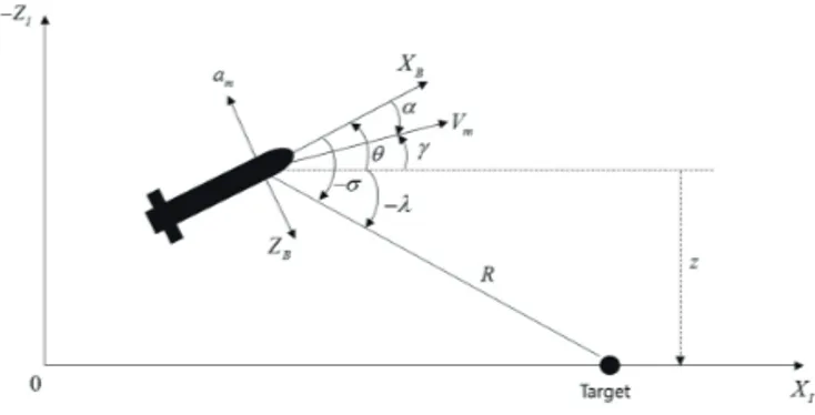
Let us consider a two-dimensional homing engagement geometry against a ground target, as shown in Fig. 1. In the inertial frame (Xt, Zt), the missile’s pitch attitude and the flight path angles are denoted as θ and r, respectively. The missile
acceleration, denoted as am, is perpendicular to velocity with a constant magnitude Vm. The notations of λ and α are the LOS angle with respect to the inertial frame and the look angle with respect to the body frame (XB, ZB), respectively. We assume that the missile acceleration controller can be
22
Fig. 1 Homing engagement geometry
Fig. 1. Homing engagement geometry
759
Tae-Hun Kim New Guidance Filter Structure for Homing Missiles with Strapdown IIR Seeker
http://ijass.org
represented by the following first order lag system.
4
approximation errors due to small angle assumptions, we define a new state vector of the filter, which consists of the unit LOS vector expressed in the body frame, the time derivative of the unit LOS vector, and the internal state variables for compensating the seeker’s time-delay. Our approach is different from the works from [11-13] in that this elimination prevents the guidance filter performance degradation caused by any implicit “range rate over range” information. The proposed guidance filter only requires the missile body attitude and rate information which can be directly measured from the inertial navigation system (INS), thus it can be easily implemented in practical homing missiles with strapdown IIR seekers. The proposed approach was proven via a series of nonlinear simulations for typical homing missions and the performance of the new filter structure was investigated in Section 4.
2. Homing Engagement with Strapdown IIR Seeker
2.1 Engagement Geometry
Let us consider a two-dimensional homing engagement geometry against a ground target, as shown in Fig. 1. In the inertial frame
X ZI, I
, the missile’s pitch attitude and the flight path angles are denoted as and , respectively. The missile acceleration, denoted as am, is perpendicular to velocity with a constant magnitude Vm. The notations of and are the LOS angle with respect to the inertial frame and the look angle with respect to the body frame
X ZB, B
, respectively. We assume that the missile acceleration controller can be represented by the following first order lag system. 1 1 m c a a a s , (1)where a and ac are the time constant of the lag system and the acceleration command, respectively.
In order to describe the homing loop for missiles equipped with the strapdown IIR seekers, we use the turning rate time constant T( ) and the kinematic relation amV m which result in the following transfer function relating the lateral acceleration to the pitch rate [14].
, (1)
where τa and ac are the time constant of the lag system and the acceleration command, respectively.
In order to describe the homing loop for missiles equipped with the strapdown IIR seekers, we use the turning rate time constant
5
In order to describe the homing loop for missiles equipped with the strapdown IIR seekers, we use the turning rate time constant T( ) and the kinematic relation amV m which result in the following transfer function relating the lateral acceleration to the pitch rate [14].
1 m m T s a V (2)
2.2 Parasite Loop Analysis
In this study, it is assumed that the optical axis of the strapdown IIR seeker is aligned with the body B
X -axis and the passive seeker provides the look angle measurements (m) only. In addition, we assume that the missile has the inertial navigation system which provides body rates and attitude angles, et cetera.
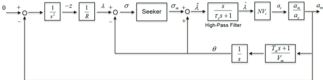
Under these assumptions with the missile models given in Eqs. (1)-(2), a simple homing guidance loop for the strapdown IIR seeker equipped missile can be developed by using the PN guidance law, as depicted in Fig. 2. In order to compute the PN guidance command, the LOS rate with respect to the inertial frame should be estimated because, unlike the gimbaled seeker, the strapdown IIR seeker provides the look angle measurements only. As shown in the homing loop given by Fig. 2, we can easily estimate the LOS rate (ˆ) by using the high-pass filter and the estimated LOS angle ( ˆ) calculated by the seeker’s look angle measurement and the missile’s pitch angle.
For the case of an ideal seeker model in which m equals to , the proposed simple homing loop could provide good enough guidance performance for intercepting stationary and/or slow moving targets. However, the homing loop can be destabilized if it is applied to real systems with loop delays. A practical IIR seeker first detects and integrates the infrared radiation for generating the image of the target. And then, appropriate image processing algorithms are performed to search, detect, and track the target from the obtained images. This series of processes requires a considerably large amount of computation time, sometimes taking up to tens of milliseconds for modern on-board processors. Therefore, the practical seeker systems inevitably produce delayed look angle measurements and transmit them to the guidance control unit (GCU).
and the kinematic relation
5
In order to describe the homing loop for missiles equipped with the strapdown IIR seekers, we use the turning rate time constant T( ) and the kinematic relation amV m which result in the following transfer function relating the lateral acceleration to the pitch rate [14].
1
m m
T s a V
(2)
2.2 Parasite Loop Analysis
In this study, it is assumed that the optical axis of the strapdown IIR seeker is aligned with the body B
X -axis and the passive seeker provides the look angle measurements (m) only. In addition, we assume that the missile has the inertial navigation system which provides body rates and attitude angles, et cetera.
Under these assumptions with the missile models given in Eqs. (1)-(2), a simple homing guidance loop for the strapdown IIR seeker equipped missile can be developed by using the PN guidance law, as depicted in Fig. 2. In order to compute the PN guidance command, the LOS rate with respect to the inertial frame should be estimated because, unlike the gimbaled seeker, the strapdown IIR seeker provides the look angle measurements only. As shown in the homing loop given by Fig. 2, we can easily estimate the LOS rate (ˆ) by using the high-pass filter and the estimated LOS angle ( ˆ) calculated by the seeker’s look angle measurement and the missile’s pitch angle.
For the case of an ideal seeker model in which m equals to , the proposed simple homing loop could provide good enough guidance performance for intercepting stationary and/or slow moving targets. However, the homing loop can be destabilized if it is applied to real systems with loop delays. A practical IIR seeker first detects and integrates the infrared radiation for generating the image of the target. And then, appropriate image processing algorithms are performed to search, detect, and track the target from the obtained images. This series of processes requires a considerably large amount of computation time, sometimes taking up to tens of milliseconds for modern on-board processors. Therefore, the practical seeker systems inevitably produce delayed look angle measurements and transmit them to the guidance control unit (GCU).
which result in the following transfer function relating the lateral acceleration to the pitch rate [14].
5
In order to describe the homing loop for missiles equipped with the strapdown IIR seekers, we use the turning rate time constant T( ) and the kinematic relation amV m which result in the following transfer function relating the lateral acceleration to the pitch rate [14].
1 m m T s a V (2)
2.2 Parasite Loop Analysis
In this study, it is assumed that the optical axis of the strapdown IIR seeker is aligned with the body B
X -axis and the passive seeker provides the look angle measurements (m) only. In addition, we assume that the missile has the inertial navigation system which provides body rates and attitude angles, et cetera.
Under these assumptions with the missile models given in Eqs. (1)-(2), a simple homing guidance loop for the strapdown IIR seeker equipped missile can be developed by using the PN guidance law, as depicted in Fig. 2. In order to compute the PN guidance command, the LOS rate with respect to the inertial frame should be estimated because, unlike the gimbaled seeker, the strapdown IIR seeker provides the look angle measurements only. As shown in the homing loop given by Fig. 2, we can easily estimate the LOS rate (ˆ) by using the high-pass filter and the estimated LOS angle ( ˆ) calculated by the seeker’s look angle measurement and the missile’s pitch angle.
For the case of an ideal seeker model in which m equals to , the proposed simple homing loop could provide good enough guidance performance for intercepting stationary and/or slow moving targets. However, the homing loop can be destabilized if it is applied to real systems with loop delays. A practical IIR seeker first detects and integrates the infrared radiation for generating the image of the target. And then, appropriate image processing algorithms are performed to search, detect, and track the target from the obtained images. This series of processes requires a considerably large amount of computation time, sometimes taking up to tens of milliseconds for modern on-board processors. Therefore, the practical seeker systems inevitably produce delayed look angle measurements and transmit them to the guidance control unit (GCU).
. (2)
2.2 Parasite Loop Analysis
In this study, it is assumed that the optical axis of the strapdown IIR seeker is aligned with the body XB-axis and the passive seeker provides the look angle measurements (σm) only. In addition, we assume that the missile has the inertial navigation system which provides body rates and attitude angles, et cetera.
Under these assumptions with the missile models given in Eqs. (1)-(2), a simple homing guidance loop for the strapdown IIR seeker equipped missile can be developed by using the PN guidance law, as depicted in Fig. 2. In order to compute the PN guidance command, the LOS rate with respect to the inertial frame should be estimated because, unlike the gimbaled seeker, the strapdown IIR seeker provides the look angle measurements only. As shown in the homing loop given by Fig. 2, we can easily estimate the LOS rate ( 5 1 m m T s a V . (2)
2.2 Parasite Loop Analysis
In this study, it is assumed that the optical axis of the strapdown IIR seeker is aligned with the body XB-axis and the passive seeker provides the look angle measurements (m) only. In addition, we assume that the missile has the inertial navigation system which provides body rates and attitude angles, et cetera.
Under these assumptions with the missile models given in Eqs. (1)-(2), a simple homing guidance loop for the strapdown IIR seeker equipped missile can be developed by using the PN guidance law, as depicted in Fig. 2. In order to compute the PN guidance command, the LOS rate with respect to the inertial frame should be estimated because, unlike the gimbaled seeker, the strapdown IIR seeker provides the look angle measurements only. As shown in the homing loop given by Fig. 2, we can easily estimate the LOS rate (ˆ) by using the high-pass filter and the estimated LOS angle ( ˆ) calculated by the seeker’s look angle measurement and the missile’s pitch angle.
For the case of an ideal seeker model in which m equals to , the proposed simple homing loop could provide good enough guidance performance for intercepting stationary and/or slow moving targets. However, the homing loop can be destabilized if it is applied to real systems with loop delays. A practical IIR seeker first detects and integrates the infrared radiation for generating the image of the target. And then, appropriate image processing algorithms are performed to search, detect, and track the target from the obtained images. This series of processes requires a considerably large amount of computation time, sometimes taking up to tens of milliseconds for modern on-board processors. Therefore, the practical seeker systems inevitably produce delayed look angle measurements and transmit them to the guidance control unit (GCU).
In the homing guidance loop of Fig. 2, the delayed look angle measurements from the seeker could destabilize the guidance system, since the unwanted feedback path, i.e., parasite loop, is made in the homing loop. For a more detailed analysis, let us take the pure delay of delay time Td as the
) by using the high-pass filter and the estimated LOS angle ( 5 1 m m T s a V . (2)
2.2 Parasite Loop Analysis
In this study, it is assumed that the optical axis of the strapdown IIR seeker is aligned with the body XB-axis and the passive seeker provides the look angle measurements (m) only. In addition, we assume that the missile has the inertial navigation system which provides body rates and attitude angles, et cetera.
Under these assumptions with the missile models given in Eqs. (1)-(2), a simple homing guidance loop for the strapdown IIR seeker equipped missile can be developed by using the PN guidance law, as depicted in Fig. 2. In order to compute the PN guidance command, the LOS rate with respect to the inertial frame should be estimated because, unlike the gimbaled seeker, the strapdown IIR seeker provides the look angle measurements only. As shown in the homing loop given by Fig. 2, we can easily estimate the LOS rate ( ˆ) by using the high-pass filter and the estimated LOS angle (ˆ) calculated by the seeker’s look angle measurement and the missile’s pitch angle.
For the case of an ideal seeker model in which m equals to , the proposed simple homing loop could provide good enough guidance performance for intercepting stationary and/or slow moving targets. However, the homing loop can be destabilized if it is applied to real systems with loop delays. A practical IIR seeker first detects and integrates the infrared radiation for generating the image of the target. And then, appropriate image processing algorithms are performed to search, detect, and track the target from the obtained images. This series of processes requires a considerably large amount of computation time, sometimes taking up to tens of milliseconds for modern on-board processors. Therefore, the practical seeker systems inevitably produce delayed look angle measurements and transmit them to the guidance control unit (GCU).
In the homing guidance loop of Fig. 2, the delayed look angle measurements from the seeker could destabilize the guidance system, since the unwanted feedback path, i.e., parasite loop, is made in the homing loop. For a more detailed analysis, let us take the pure delay of delay time Td as the
) calculated by the seeker’s look angle measurement and the missile’s pitch angle.
For the case of an ideal seeker model in which σm equals
to σ, the proposed simple homing loop could provide good
enough guidance performance for intercepting stationary and/or slow moving targets. However, the homing loop can be destabilized if it is applied to real systems with loop delays. A practical IIR seeker first detects and integrates the infrared radiation for generating the image of the target. And then,
appropriate image processing algorithms are performed to search, detect, and track the target from the obtained images. This series of processes requires a considerably large amount of computation time, sometimes taking up to tens of milliseconds for modern on-board processors. Therefore, the practical seeker systems inevitably produce delayed look angle measurements and transmit them to the guidance control unit (GCU).
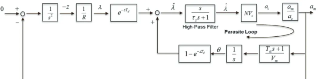
In the homing guidance loop of Fig. 2, the delayed look angle measurements from the seeker could destabilize the guidance system, since the unwanted feedback path, i.e., parasite loop, is made in the homing loop. For a more detailed analysis, let us take the pure delay of delay time Td as the strapdown IIR seeker model. The LOS angle estimated from the delayed seeker measurement then can be derived as
6
strapdown IIR seeker model. The LOS angle estimated from the delayed seeker measurement then can be derived as
ˆ 1 d d d m sT sT sT e e e , (3)Using this LOS angle estimate, the LOS rate can be estimated through the 1st-order high-pass filter as follows:
ˆ ˆ 1 1 1 1 1 1 1 d d d d s sT sT s sT sT s s s s e e s e e s s . (4)From Eq. (4), it can be seen that the estimated LOS rate expression includes both the true kinematic LOS rate and pitch rate information. The obtained LOS rate estimate is used to generate the guidance command, thus creating the undesirable body motion feedback loop in the guidance loop. Based on the Eqs. (3)-(4) and Fig. 2, the homing guidance loop, that contains the unwanted parasite loop caused by the seeker’s delay, can be represented as Fig. 3. As shown in the Fig. 3, the LOS rate estimation and the guidance command are affected by the delayed body motion, thereby leading to poor guidance performance and/or loop instability.
From Eq. (3) and Fig. 3, it is seen that the adversarial effects due to the parasite loop can be mild if the delay time Td and/or missile’s body rates are small. However, it may be difficult for the real systems to always satisfy these conditions during the flight. First, sufficient image acquisition and processing times should be given for obtaining more accurate target information, thus significant amount of time delay exists in the IIR seeker homing missile system. Second, it is hard to guarantee sufficiently small missile acceleration and body motion during the entire flight because there are uncertainties and disturbances in the real world situations, even though the required acceleration level decreases as the homing missile approaches the target. Having said that, we should consider the
,
(3) Using this LOS angle estimate, the LOS rate can be estimated through the 1st-order high-pass filter as follows:
6
In the homing guidance loop of Fig. 2, the delayed look angle measurements from the seeker could destabilize the guidance system, since the unwanted feedback path, i.e., parasite loop, is made in the homing loop. For a more detailed analysis, let us take the pure delay of delay time Td as the strapdown IIR seeker model. The LOS angle estimated from the delayed seeker measurement then can be derived as
ˆ 1 d d d m sT sT sT e e e (3) Using this LOS angle estimate, the LOS rate can be estimated through the 1st-order high-pass filter as follows:
ˆ ˆ 1 1 1 1 1 1 1 d d d d s sT sT s sT sT s s s s e e s e e s s (4)From Eq. (4), it can be seen that the estimated LOS rate expression includes both the true kinematic LOS rate and pitch rate information. The obtained LOS rate estimate is used to generate the guidance command, thus creating the undesirable body motion feedback loop in the guidance loop. Based on the Eqs. (3)-(4) and Fig. 2, the homing guidance loop, that contains the unwanted parasite loop caused by the seeker’s delay, can be represented as Fig. 3. As shown in the Fig. 3, the LOS rate estimation and the guidance command are affected by the delayed body motion, thereby leading to poor guidance performance and/or loop instability.
From Eq. (3) and Fig. 3, it is seen that the adversarial effects due to the parasite loop can be mild if the delay time Td and/or missile’s body rates are small. However, it may be difficult for the real systems to always satisfy these conditions during the flight. First, sufficient image acquisition and processing times should be given for obtaining more accurate target information, thus significant amount of time delay exists in the IIR seeker homing missile system. Second, it is hard to guarantee sufficiently small missile acceleration and body motion during the entire flight because there are
.
(4)
From Eq. (4), it can be seen that the estimated LOS rate expression includes both the true kinematic LOS rate and pitch rate information. The obtained LOS rate estimate is used to generate the guidance command, thus creating the undesirable body motion feedback loop in the guidance loop. Based on the Eqs. (3)-(4) and Fig. 2, the homing guidance loop, that contains the unwanted parasite loop caused by the seeker’s delay, can be represented as Fig. 3. As shown in the Fig. 3, the LOS rate estimation and the guidance command are affected by the delayed body motion, thereby leading to poor guidance performance and/or loop instability.
From Eq. (3) and Fig. 3, it is seen that the adversarial effects
.
Fig. 2 Simple homing guidance loop for strapdown IIR seeker
Fig. 2. Simple homing guidance loop for strapdown IIR seeker
DOI: http://dx.doi.org/10.5139/IJASS.2017.18.4.757
760
Int’l J. of Aeronautical & Space Sci. 18(4), 757–766 (2017)due to the parasite loop can be mild if the delay time Td and/ or missile’s body rates are small. However, it may be difficult for the real systems to always satisfy these conditions during the flight. First, sufficient image acquisition and processing times should be given for obtaining more accurate target information, thus significant amount of time delay exists in the IIR seeker homing missile system. Second, it is hard to guarantee sufficiently small missile acceleration and body motion during the entire flight because there are uncertainties and disturbances in the real world situations, even though the required acceleration level decreases as the homing missile approaches the target. Having said that, we should consider the latency information of the seeker systems in designing the guidance filter, in order to estimate the LOS angle and rate while minimizing the parasitic effects.
3. Guidance Filter for LOS Angle and Rate
Es-timation
In this section, we first propose a new guidance filter structure, including the stochastic dynamic models and the measurement equations, for general three-dimensional homing guidance problem. Then in order for the readers’ intuitive understanding, we apply the proposed guidance filter structure to the two-dimensional vertical homing problem given in Fig. 1, by using the Extended Kalman Filter (EKF).
3.1 System Dynamic Model
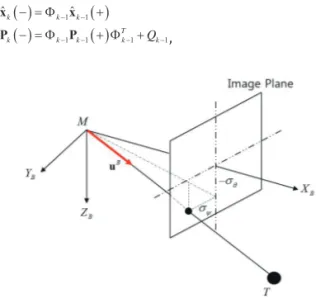
3.1.1 Unit Vector along LOSTo design the guidance filter for estimating the LOS angles and rates with respect to the inertial frame, we define a unit vector u which aligns with the LOS from the missile to the target. The time derivative of the unit vector in the inertial frame is then defined as
7
latency information of the seeker systems in designing the guidance filter, in order to estimate the LOS angle and rate while minimizing the parasitic effects.
3. Guidance Filter for LOS Angle and Rate Estimation
In this section, we first propose a new guidance filter structure, including the stochastic dynamic models and the measurement equations, for general three-dimensional homing guidance problem. Then in order for the readers’ intuitive understanding, we apply the proposed guidance filter structure to the two-dimensional vertical homing problem given in Fig. 1, by using the Extended Kalman Filter (EKF).
3.1 System Dynamic Model 3.1.1 Unit Vector along LOS
To design the guidance filter for estimating the LOS angles and rates with respect to the inertial frame, we define a unit vector u which aligns with the LOS from the missile to the target. The time
derivative of the unit vector in the inertial frame is then defined as
ILOS I d dt u ω u , (5)
where denotes the vector cross product andωILOS is the rotation angular velocity of the LOS; that is, ωILOS is the vector of the LOS rate. For calculating the PN guidance command, the LOS rate perpendicular to the LOS is required, which is given by
ILOS I d dt u ω u , (6)
where ωILOS is the LOS rate vector normal to the LOS. It is noted from Eq. (6) that the LOS rate
perpendicular to the LOS can be obtained if the unit vector and its time derivative in the inertial frame are given.
The strapdown IIR seeker provides the look angle measurements with respect to the body frame as shown in Figs. 1 and 2; which implies that the seeker measures the direction of the unit LOS vector in
, (5)
where × denotes the vector cross product and ωILOS is the
rotation angular velocity of the LOS; that is, ωILOS is the vector of the LOS rate. For calculating the PN guidance command, the LOS rate perpendicular to the LOS is required, which is given by
7
latency information of the seeker systems in designing the guidance filter, in order to estimate the LOS angle and rate while minimizing the parasitic effects.
3. Guidance Filter for LOS Angle and Rate Estimation
In this section, we first propose a new guidance filter structure, including the stochastic dynamic models and the measurement equations, for general three-dimensional homing guidance problem. Then in order for the readers’ intuitive understanding, we apply the proposed guidance filter structure to the two-dimensional vertical homing problem given in Fig. 1, by using the Extended Kalman Filter (EKF).
3.1 System Dynamic Model 3.1.1 Unit Vector along LOS
To design the guidance filter for estimating the LOS angles and rates with respect to the inertial frame, we define a unit vector u which aligns with the LOS from the missile to the target. The time
derivative of the unit vector in the inertial frame is then defined as
ILOS I d dt u ω u , (5)
where denotes the vector cross product andωILOS is the rotation angular velocity of the LOS; that is, ωILOS is the vector of the LOS rate. For calculating the PN guidance command, the LOS rate perpendicular to the LOS is required, which is given by
ILOS I d dt u ω u , (6)
where ωILOS is the LOS rate vector normal to the LOS. It is noted from Eq. (6) that the LOS rate
perpendicular to the LOS can be obtained if the unit vector and its time derivative in the inertial frame are given.
The strapdown IIR seeker provides the look angle measurements with respect to the body frame as shown in Figs. 1 and 2; which implies that the seeker measures the direction of the unit LOS vector in
, (6)
where
7
latency information of the seeker systems in designing the guidance filter, in order to estimate the LOS angle and rate while minimizing the parasitic effects.
3. Guidance Filter for LOS Angle and Rate Estimation
In this section, we first propose a new guidance filter structure, including the stochastic dynamic models and the measurement equations, for general three-dimensional homing guidance problem. Then in order for the readers’ intuitive understanding, we apply the proposed guidance filter structure to the two-dimensional vertical homing problem given in Fig. 1, by using the Extended Kalman Filter (EKF).
3.1 System Dynamic Model 3.1.1 Unit Vector along LOS
To design the guidance filter for estimating the LOS angles and rates with respect to the inertial frame, we define a unit vector u which aligns with the LOS from the missile to the target. The time
derivative of the unit vector in the inertial frame is then defined as
ILOS I d dt u ω u , (5)
where denotes the vector cross product andωILOS is the rotation angular velocity of the LOS; that is, ωILOS is the vector of the LOS rate. For calculating the PN guidance command, the LOS rate perpendicular to the LOS is required, which is given by
ILOS I d dt u ω u , (6)
where ωILOS is the LOS rate vector normal to the LOS. It is noted from Eq. (6) that the LOS rate
perpendicular to the LOS can be obtained if the unit vector and its time derivative in the inertial frame are given.
The strapdown IIR seeker provides the look angle measurements with respect to the body frame as shown in Figs. 1 and 2; which implies that the seeker measures the direction of the unit LOS vector in
is the LOS rate vector normal to the LOS. It is noted from Eq. (6) that the LOS rate perpendicular to the LOS can be obtained if the unit vector and its time derivative in the inertial frame are given.
The strapdown IIR seeker provides the look angle measurements with respect to the body frame as shown in Figs. 1 and 2; which implies that the seeker measures the direction of the unit LOS vector in the body frame. To directly implement the seeker’s measurements in the guidance filter, therefore, we suggest the unit vector expressed in the body frame, uB, and its time derivative expressed in the body frame,
8
the body frame. To directly implement the seeker’s measurements in the guidance filter, therefore, we suggest the unit vector expressed in the body frame, uB, and its time derivative expressed in the body
frame, B
I
d
dtu , for the filter states to be estimated.
3.1.2 1st-Order Pade Approximation for Time-Delay
As mentioned in the previous section, the seeker’s latency is the important issue in the strapdown IIR seeker equipped homing missiles. In general, the latency of the seeker depends on image processing algorithms, target types, and flight environment, et cetera. This implies that the amount of time delay is not constant during the flight. However, the maximum possible amount of time delay caused by the seeker systems could be assessed and predicted via experimental tests under a variety of engagement geometry, environmental condition, and image processing algorithms. Therefore the sampling interval of the seeker system (from sensing start to transmission to GCU) can be kept constant as the predicted maximum delay time, and the strapdown IIR seeker can be simply modelled by the pure delay with the constant time delay of Td. This implies that we can practically have the seeker measurement to be consistently delayed by Td without causing underestimation or overestimation, by appropriate message management and passing algorithms such as time tagging.
We use the first order Pade approximation for modelling the pure delay associated with the seeker system as follows. 2 2 d B sT d d B d s T e s T u u . (7) Here, B d
u is the delayed unit LOS vector expressed in the body frame. Then, we can derive the state-space equation of Eq. (7) in the time domain as
2 4 B d d d d B B d d d dt T T x x u u x u . (8) , for the filter states to be estimated.
3.1.2 1st-Order Pade Approximation for Time-Delay
As mentioned in the previous section, the seeker’s latency is the important issue in the strapdown IIR seeker equipped homing missiles. In general, the latency of the seeker depends on image processing algorithms, target types, and flight environment, et cetera. This implies that the amount of time delay is not constant during the flight. However, the maximum possible amount of time delay caused by the seeker systems could be assessed and predicted via experimental tests under a variety of engagement geometry, environmental condition, and image processing algorithms. Therefore the sampling interval of the seeker system (from sensing start to transmission to GCU) can be kept constant as the predicted maximum delay time, and the strapdown IIR seeker can be simply modelled by the pure delay with the constant time delay of Td. This implies that we can practically have the seeker measurement to be consistently delayed by
Td without causing underestimation or overestimation, by appropriate message management and passing algorithms such as time tagging.
24
Fig. 3 Parasite loop due to seeker’s latency
Fig. 3. Parasite loop due to seeker’s latency