P2-27 / M. Shin
IMID 2009 DIGEST •
Abstract
A novel method to control the viewing direction by moving aperture location in 4-f illumination optics to control light direction is proposed. Based on integral imaging principle, the relayed point light sources by 4-f optics are modulated by a spatial light modulator, displaying three-dimensional images. In the proposed method, we locate the aperture, which acts as a band pass filter, around an optic axis to control the light direction. Resultantly, assuming that we know the viewer position by a tracking system, we can display appropriate three-dimensional images over large viewing angle
1. Introduction
Three-dimensional (3D) display has been studied actively, nowadays. Many different kinds of 3D display techniques have been proposed, including stereoscopic, autostereoscopic, holographic, and volumetric display techniques. Among the 3D display techniques, integral imaging (II) method has great advantages in displaying full colored 3D images with continuous horizontal and vertical parallaxes. However, there are some drawbacks to be overcome such as small viewing angle (VA), low resolution and limitation of depth.[1,2]
To overcome the limitation of small VA, light direction controlling technique by moving aperture is proposed. In typical VA enhancing methods, VA is increased while the viewing direction is fixed.[3,4] In contrast, the proposed method controls viewing direction by moving the aperture in a 4-f illumination optics with fixed VA. In previous VA enhancing techniques, fixed amount of information extents covers enlarged VA, reducing the amount of the information extents assigned for each solid angle. However, in the proposed method, the whole information extents are assigned to small VA,
enhancing the amount of the information extents assigned to each solid angle. The VA in the proposed method defines not the angular range of the viewer but the error tolerance of viewer position detection. Therefore, we can acquire appropriate 3D images over large angle according to viewer positions. We have reported initial version of the proposed method which locates the aperture on Fourier plane.[5] In this paper, we expand the proposed method to include the case locating the aperture in front of or behind of the Fourier plane. Followings are the principle of the proposed method and its preliminary experimental results.
2. Principle of proposed method
The proposed method uses 4-f illumination optics with Fresnel lenses in the generation of the point light source array. The aperture is located at optic axis or non-optic axis to control the propagation angle of each point light source. At the optic axis, if the aperture is located at the Fourier plane of 4-f optics, light rays emanating from point light sources go to the forward direction.[5] If the aperture is located in front of or behind of the Fourier plane, the light are converged or diverged, which enhances the VA for real images or virtual images. At the non-optic axis, if the aperture is located at the Fourier plane, the light rays from all point light sources emanate with a same angle which is determined by lateral deviation of the aperture from optic axis. [5] When the aperture is in front of or behind Fourier plane, light propagates to converge to a point for real image or to diverge from a point for virtual image with a certain angle. For the case of converging and diverging illumination, the propagation angles of each point light source are slightly different. Figure 1 describes concept of the proposed method. Figures 1(a) and (b) show the propagation angle when the
Viewing Angle Enhancement of Light Direction
Controllable Integral Imaging Three-dimensional Display
System by Moving Aperture in 4-f Illumination Optics
Minyoung Shin, Jae-Hyeung Park*, Nam Kim
College of Electrical & Computer Engineering, Chungbuk National University, Cheong-ju, Korea
TEL: +82-43-261-3598, e-mail: [email protected]
P2-27 / M. Shin
• IMID 2009 DIGEST
aperture is centered at the optic axis and the non-optic axis. In those two cases, the propagation angle of each point light source is derived from the Eqs. (1) and (2) as followings: _
tan
1{
2(
f
a
)}
f
ny
opticaxis n=
−
−ϕ
, (1) _tan
1{
2(
)
}
a
h
a
f
f
ny
opticaxis non n=
−
+
− −ϕ
, (2)where ny is a position of the point light source, f is focal length of Fresnel lens, a is the distance from first Fresnel lens to the aperture location,
ϕ
is a propagation angle of each point light source and h is a distance of the aperture center from optic axis.Figure 2 depicts the light distribution of converging illumination and diverging illumination case. Figure 2(a) is the converging illumination case where the propagation angle from the point light sources is determined by Eqs. (1) and (2) according to the lateral position of the aperture. Figure 2(b) is the diverging illumination case which can be described in the same manner.
3. Experimental results
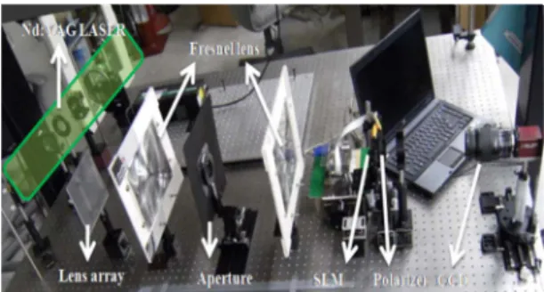
Figure 3 shows the experimental setup. The light source is coherent Nd-YAG 532nm laser, the focal length of Fresnel lens is 220mm. To make the point light source array, we used 1mm pitch lens array. The pixel pitch of SLM is 0.036mm. The point light sources generated by the lens array are relayed to the
(a)
(b)
Fig. 2. Light distribution according to the aperture location (a) Converging illumination case, (b) Diverging illumination case.
back focal plane of second Fresnel lens and modulated by the SLM to make the 3D images. The aperture plays a role of band pass filter limiting the diverging angle and controlling the propagation direction of the point light sources. The propagation angle of each point light source is not parallel each other but convergent or divergent according to the aperture location as stated earlier. When the aperture is located in front of the Fourier plane, the light rays are convergent to a certain point. This propagation direction of the light rays from the PLSs coincides with the integrated direction of the 3D images. Therefore the real 3D images are formed with enhanced VA. Moreover, by shifting the aperture laterally, viewing direction can be controlled, which ensures even larger viewing range if the observer position is detected.
When the aperture is located behind of the Fourier plane, the light rays are divergent from a certain point. Again, the VA of the virtual images is enhanced in the same manner as converging illumination case
Fig. 3. Experimental setup
(a) (b)
Fig. 1. Concept of proposed method (a) Aperture is centered at optic axis, (b) Aperture is biased to non-optic axis.
P2-27 / M. Shin IMID 2009 DIGEST • (a) (b) (c)
Fig. 4. 3D images according to the aperture location (a) Collimating illumination case when the aperture is on Fourier plane. (b) Converging illumination case when the aperture is in front of the Fourier plane. (c) Diverging illumination case when the aperture is behind of the Fourier plane.
Figure 4 shows the displayed 3D images when the aperture is at Fourier plane, in front of the Fourier plane and behind of the Fourier plane indicating the collimating, the converging and the diverging illumination case. As we can see in Fig. 4(a), the total VA according to viewer’s position for the collimating illumination case is limited by the focal length and the diameter of lens array so that it cannot exceed the VA of lens array itself. However, as we can see in Fig. 4(b), the VA of the real image ‘V’ is enhanced in the converging illumination case. The virtual image ‘A’ is also displayed with larger VA in the diverging illumination case as can be seen in Fig. 4(c). Therefore, it can be confirmed that the VA is enhanced for the real image in the converging illumination case and for the virtual image in the diverging illumination case.
4. Summary
We propose the VA enhancement of light direction controllable integral imaging 3D display system by moving aperture in 4-f illumination optics. By moving the aperture between two Fresnel lenses, the light direction from the relayed PLSs can be controlled to be convergent for real images or divergent for virtual images. It can be best combined with position tracking system to give the freedom of viewer’s position.
Acknowledgements
"This research was supported by the MKE (The Ministry of Knowledge Economy), Korea under the ITRC (Information Technolgy Research Center) Support program supervised by the IITA (Institute for Information Technology Advancement)"
(IITA-2009-C1090-0902-0018)
5. References
1. R. Martínez-Cuenca, H. Navarro, G. Saavedra, B. Javidi, and M. Martinez-Corral, Opt. Express 15, pp.16255-16260(2007).
2. J.-H. Park, H.-R. Kim, Y. Kim, J. Kim, J. Hong, S.-D. Lee, and B. Lee, Opt. Lett. 29, 2734-2736, (2004).
3. S. Jung, J.-H. Park, H. Choi, and B. Lee, Appl. Opt. 42, 2513-2520 (2003).
4. S.-W. Min, J. Kim, and B. Lee, Opt. Lett. 29 2420-2422 (2004).
P2-27 / M. Shin
• IMID 2009 DIGEST
5. J.-H. Park, M. Shin and N. Kim, SID’09 Technical Digest, Vol. 41, p.607 (2009).