Conceptual Design of a Small Scale High Temperature and High Pressure Gas Loop
S. D. Hong, D. S. Oh, W. J. Lee, J. H. Kim, Y. J. Shin, J. H. ChangKorea Atomic Energy Research Institute, Yuseong-Gu, Daejeon, Korea, 305-600, [email protected] 1. Introduction
The High Temperature Gas Cooled Reactor (HTGR) which raises the coolant outlet temperature up to 950 °C is quit suitable hydrogen production nuclear reactor by connection with a thermo-chemical cycle. Because of the operational temperature of conventional metallic heat exchanger is limited to 830°C at a reactor operating pressure (4 MPa), one of the key problems of nuclear hydrogen production is developing a process heat exchanger (PHE). The PHE should have both the high corrosion resistance against sulfur trioxide (SO3 ) and the strong thermal
and mechanical resistances at very high temperatures (850~950°C). Current research trends of PHE could be divided into two streams; one is study of ceramic heat exchanger to reinforce thermal and mechanical strengths against high pressure and temperature; another is study of ceramic coating on a super alloy plate to increase corrosion resistance of PHE. Most of above mentioned research works are in a conceptual design stage. It is required corresponding experimental facility to test the various design outputs of PHE. We designed small scale high temperature gas loop conceptually to simulate HTGR operational conditions. The design of loop focused various test of small scale PHE and the loop would be used screening of PHE candidates and verifying their design performances.
2. Primary loop design
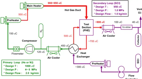
The primary loop of small scale high temperature experimental facility composed of a compressor for flow circulation, a pre-heater rising the gas temperature to 500°C, a main heater rising the gas to 1000 °C, a hot gas duct, a process heat exchanger (test section) for hydrogen generation, a heat exchanger, an air cooler and nitrogen supply system as shown in Figure 1. The nitrogen supply system also has a
function of system pressure control by pressure regulator. Gas flow adjusted systematically to an experimental condition using the three devices, inverter in the compressor system, inlet throttling valve, and flow bypass valve. The design condition of the primary loop is as follows;
- Working fluid Helium or Nitrogen
- Design Temperature 1000 °C
- Design pressure 4 ~ 6 MPa.
- Design Flow 2.0 kg/min
2.1 Mechanical Requirements
Fluid induced vibration (FIV)
FIVs are the results of the nitrogen or helium impinging on the heater elements, heat exchanger
tube, internal insulators of heater vessel and hot-gas-duct. The flow can cause vibration that can damage a flexible structure. The reduced velocity for the onset of whirling instability is [1,2]
2
2
D
m
K
fD
U
Criticalρ
πζ
=
. (1)Acoustic vibration (AV)
The sources of AV are a series of interconnected ducts and cavities. Acoustic noise can damage plates and shells lining the ducts and cavities of the primary loop. The speed of sound in a gas is [2]
M
T
Sℜ
=
γ
υ
, (2)Where
γ
is the ratio of the specific heat at constant pressure to that at constant volume.Thermal stress
Thermal stresses are induced in any restrained component by the tendency of materials to expand as they are heated. Thermal stresses are generated as components attempt to expand against restraints provided by adjacent structural supports or as a result of a non-uniform temperature distribution within the body.
The requirements to prevent the loop from FIV and AV are obtained by equation (1) and (2). The design specifications of the main components are derived from the requirements of nitrogen gas because both FIV and AV can be more significant in the loop operating in nitrogen due to the much lower reduced velocity and speed of sound in nitrogen compared to helium (see Table 1). Because the main heater, HGD and PHE are exposed very high thermal stresses, their pressure vessels should be
Heat Exchanger Compressor SO 3 500 oC 150 oC ~900 oC
Figure 1. Schematics of Small Scale High Temperature Gas Loop
Primary Loop (He or N2) * Design T : 1000 oC * Design P : 4~ 6 MPa * Design Flow : 2.0 kg/min
900~950 oC Secondary Loop (SO3)
* Design T : 950 oC * Design P : 1.0 MPa * Design Flow : 1.0 kg/min
Air Cooler PreHeater Flowmeter N2 Air Cooler Vent O2 Flow Controller 120 oC 500 oC 450 oC 100 oC Co ll ecto r Test Section (PHE) Main Heater PreHeater ~300 oC ~700 oC
Hot Gas Duct
Scrubber
40 oC Transactions of the Korean Nuclear Society Autumn Meeting
installed the internal thermal insulators. The insulator material is Kaowool, a ceramic fiber glass which has the conductivity of 0.2 W/mK.
2.2 Design of Main Components
High Temperature Heater
Because of its high operating temperature of 950 °C, a graphite tube is used as the high temperature heating element. The graphite tube can withstand over 2000 °C at oxygen free environment. The heater vessel is internally insulated between the vessel and the internal liner to prevent thermal failure of the vessel. The internal liner also has a function of a reflector against thermal radiation emitted by the graphite heater element. Hot Gas Duct (HGD)
The HGD is connected between main heater and process heat exchanger. A thermal insulator with a Hastelloy X liner is installed internal of the pressure pipe to keep pressure boundary of pipe (or protect pipe failure) from the 1000 °C internal gas temperature. The empirical equation of effective thermal conductivity of the thermal insulator for horizontal tube is [3]
),
(
10
70
.
4
0196
.
0
4T
K
eff −×
+
=
λ
(3)For vertical tube,
).
(
10
04
.
6
0201
.
0
4T
K
eff −×
+
=
λ
(4)The minimum thickness of insulator can be obtained the following heat transfer (HT) relationship.
Heat loss through conduction
= Pipe surface convection and Radiation HT. (5)
Process Heat Exchanger (Test Section)
The process heat exchanger (PHE) is connected between HGD and low temperature heat exchanger. The design and manufacturing of a 10kW PHE is now on the developing in KAERI. A minimum size of the inlet and outlet nozzles of PHE is depend on the size of pressure pipe of HGD which should be connected to the PHE. The minimum size of nozzles is calculated 90mm.
3. Secondary loop design
The secondary loop consists of preheater, heat exchanger, PHE, air cooler, scrubber and collection tank. The SO3 flows in
the secondary loop as a gas, and its flow rate is controlled by a
mass flow controller. The SO3 is preheated to 500°C from
300°C in the preheater. It is decomposed into SO2 and O2 in the
PHE. The mixture of SO2, O2, and not reacted SO3 is cooled to
100°C in the air cooler. SO2 and SO3 in the mixture gas have to
be removed before it is released into the atmosphere. Most of SO2 can be removed through the scrubbing system. SO3 can be
collected in the collection tank as a liquid. The collection tank
should be maintained between 32°C and 45°C, since SO3
vaporizes at 45°C and solidifies at 32°C (in case of ß-SO3). The
collection tank should have an over- pressure protection device,
for there is a possibility that SO3 will explode when the
temperature of the tank rises above 45°C at any reason. The design condition of the secondary loop is as follows;
- Working fluid SO2, O2 and SO3 mixture
- Design Temperature 950 °C
- Design pressure 1.0 MPa.
- Design Flow 1.0 kg/min
4. Summary
We designed small scale high temperature (~950 °C) and high pressure (~6MPa) gas loop conceptually to simulate HTGR operational conditions. The design of the loop focused various test of small size (10kW) process heat exchanger. We arranged the components of primary gas loop and secondary SO3 loop as
Figure 1. Mechanical requirements are checked to the all components and local design requirements are obtained especially for safe design of a main heater, a hot-gas-duct and a process heat exchanger in nitrogen medium (Table 1). Pressure vessel exposed very high thermal stress is needed a special thermal insulator in vessel internal. We found the minimum nozzle size of PHE (90mm) that will guarantee from thermal failure and severe heat loss of the test loop. Very toxic SO3
secondary loop is needed a scrubber and a SO3 collector for
safety and contamination of environment. ACKNOWLEDGEMENTS
This study has been carried out under the Nuclear R & D Program supported by the MOST of Korea.
REFERENCES
[1] R. D. Blevins, “ Flow-Induced Vibration,” 2nd ed., Van
Nostrand Reinhold, New York, 1990.
[2] G. Melese and R. Katz, “ Thermal and Flow Design of Helium-Cooled Reactors,” American Nuclear Society, 1984. [3] M. Hishida et.al., "Thermal Performance Test of the Hot Gas Ducts of HENDEL," Nuclear Eng. & Design, Vol. 83, 1984.
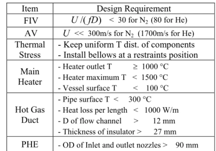
Table 1. Design Requirements for Primary Loop
Item Design Requirement
FIV
U
/( fD
)
< 30 for N2 (80 for He) AVU
<< 300m/s for N2 (1700m/s for He) ThermalStress - Keep uniform T dist. of components - Install bellows at a restraints position Main Heater - Heater outlet T ≥ 1000 °C - Heater maximum T < 1500 °C - Vessel surface T < 100 °C Hot Gas Duct - Pipe surface T < 300 °C - Heat loss per length < 1000 W/m - D of flow channel > 12 mm - Thickness of insulator > 27 mm
PHE - OD of Inlet and outlet nozzles > 90 mm