P2-55 / S.-H. Ji
• IMID 2009 DIGEST
Abstract
Compared to the indium zinc oxide (IZO) film fabricated by micro-powder target, the IZO film with nano-powder target exhibited improved optoelectronic properties of wide band-gap, high transmittance, surface uniformity, and low sheet resistance due to the high film density.
1. Introduction
Transparent conductive oxide(TCO) films have been widely used as transparent electrodes of optoelectronic devices such as a touch screen, flat panel displays(FPDs), and organic solar cells[1-3]. A zinc-doped indium oxide(IZO) film has drawn enormous interest as anodes for several devices because of their high conductivity, transparency over the visible range, and their high work function[4-5]. Moreover, the TCO films including ZnO component are more stable against hydrogen plasma, more abundant, and less expensive in comparison with the conventional tin-doped indium oxide(ITO) film[6]. Recently, the enhanced characteristics and application of the TCO film with nano-powder are reported elsewhere. In order to obtain a low electric resistance and high transparency in the ITO film, generally, it is necessary to set the substrate temperature at 200-300
oC. However, since the ITO film prepared at high
temperature has a poor etching property and a very rough surface morphology, they can damage to process and lifetime of the devices. In particular, it is difficult to set the substrate temperature at 200-300 oC
and to make an ITO film with a low electric resistance and high transparency when ITO layer was deposited on polymer substrates such as polyethylene terephthalate(PET), polyethylene naphtalate(PEN), polycarbonate(PC) for flexible display. On the other hand, the IZO film deposited at a comparative low temperature has a high transmittance over 90 % in the
visible light range and a low resistivity of ~10-4 Ω⋅cm. In this work, the electrical, optical, and structural properties of the IZO films deposited with sputtering target of nano- or micro-size powder by using rf-magnetron sputtering system were investigated. A mixed IZO powder with a composition ratio of 78:22 wt.%(In2O3:ZnO) with nano- and micro-size power
were calcined at 1000 oC in air for two hours and were
used as a sputtering target. The IZO films fabricated by nano- and micro-powder target were respectively refer to as IZO(n) and IZO(m), and their film properties were also compared.
2. Experimental
In2O3(99.999%) and ZnO(99.999%) nano- and
micro-powder with a composition ratio of 78:22 wt.% were respectively mixed for 24 hours by ball mill. The mixed powder were calcined at 1000 oC in the air for
two hours and it were used as a sputter targets for the IZO(n) and IZO(m) films. IZO(n) and IZO(m) films were respectively deposited by conventional rf-magnetron sputtering system. The depositions were carried out at room temperature(R.T.) in a pure Ar gas pressure of 2 x 10⁻³ Torr. Corning 7059 glass was used
as substrates. IZO(n) and ITO(m) films were deposited with a parallel distance of 6.5 cm between substrate and target surface, and their film thicknesses were fixed with 180 nm. The deposition rate is constantly maintained as about 18-20 nm/min by rf power of 100 W. For the nano-powder target and micro-powder target, their surface morphologies were analyzed by field emission-scanning electron microscope(FE-SEM, JEOL Co.). The film thickness were measured by using an α-step profiler(VEECO Co.).
Enhanced Properties of IZO Thin Film Prepared by
Nano-Powder Target
Seung-Hun Ji, Hyun-Oh Youn, Sung-Bo Seo, Mi-Sun Kim, Sun-Young
Sohn, Jong-Jae Kim, and Hwa-Min Kim
Department of Electronics & Display Engineering, Catholic University of Daegu, 330 Hayang-Eup, Gyeongsan-Si, Gyeongbuk, Republic of Korea
TEL:+82-53-850-2739, e-mail: [email protected]
P2-55 / S.-H Ji
IMID 2009 DIGEST •
3. Results and discussion
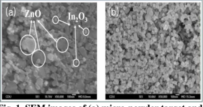
Fig. 1 shows the SEM images of the targets prepared using (a) micro-powder and (b) nano-powder. In2O3 and ZnO particles in Fig. 1 (a) are certainly
distinguished due to difference of their size, and also this target has somewhat loose structure while the nano-powder target in Fig. 1 (b) is difficult to discriminate between In2O3 and ZnO particles.
Because the two particles in Fig. 1 (b) were combined by repetition of pressure and calcination in process of the target preparation, the target with nano-powder shows considerably the dense structure as compared with the micro-powder target, which can affect the grown characteristics such as the grains, the deposition rate of films, the film density, and the adhesion to substrate.
Fig. 1. SEM images of (a) micro-powder target and (b) nano-powder target.
Table 1 shows the sheet resistance of the IZO(m) and IZO(n) films as a function of the deposition thickness. The IZO(n) films deposited by nano-powder target at R.T. showed a lower sheet resistances than the IZO(m) films with micro-powder target. The sheet resistances were rapidly decreased with increasing film thickness with unit surface in all the samples. All IZO films were deposited on the glass substrates with a size of 5×5 cm2 to measure the sheet
resistance of the films.
TABLE 1. Sheet resistance of IZO films as functions of film thickness.
Thicknesses of films IZO (micro-powder) IZO (nano-powder) 150 nm 37.5 Ω/□ 32.1 Ω/□ 200 nm 26.3 Ω/□ 25.5 Ω/□ 250 nm 20.3 Ω/□ 17.8 Ω/□ 300 nm 16.2 Ω/□ 14.5 Ω/□ 400 nm 12.8 Ω/□ 11.1 Ω/□
In general, the sheet resistance(R) is inversely proportional to the film thickness like R = ρ/t, where ρ and t are the electrical resistivity and film thickness, respectively. The sheet resistance are calculated by ρ = 5.1 x 10⁻⁴ Ω·cm for IZO(m) film and ρ = 4.5 x 10⁻⁴
Ω·cm for IZO(n) film. The measured resistances of films with the thickness of 180 nm well agreed with the calculated values. The low electrical resistivity of IZO(n) film is mainly contributed to the surface uniformity and the improved film density due to the nano-size powder.
4. Summary
The electrical and optical properties of IZO films prepared by nano-powder target showed the enhanced performance with the higher conductivity and the improved structural property compared with the films with micro-powder target. It was related to the improvement of the film density due to the increased refractive index.
5. Acknowledgements
This research was financially supported by industry academic cooperation project for a research center attached to a company, which some graduate students are participating in the second stage of BK21.
6. References
1. G. N. Ito, Y. Sato, P. K. Song, A. Kaijio, K. Inoue and Y. Shigesato, Thin Solid Films, 496, 99 (2006). 2. B. Shin and C. W. Chung, J. Korean Ind. Eng.
Chem, 15, 300 (2004).
3. J. S. Hong, B. R. Rhee, H. M. Kim, K. C. Je and Y. J. Kang and J. S. Ahn, Thin Solid Films, 467, 158 (2004).
4. C. H. Park, H. J. Lee, H. B. Kim and G. H. Lee, J. Kor. Inst. Surf. Eng., 38[5], 188 (2005).
5. B. Yaglioglu, Y. J. Huang, H. Y. Yeom and D. C. Paine, Thin Solid Films, 496, 89 (2006).
6. S. T. Kim, J. H. Lee, J. Y. Yang, S. W. Ryu, J. S. Hong, W. P. Hong, J. J. Kim, H. M. Kim, J. M. Yang and S. H. Park, J. Korean Phys. Soc., 50, 662 (2007).