INTRODUCTION
Polytetrafluoroethylene (PTFE) is widely used for a variety of applications due to an outstanding combination of chemical and physical properties such as high-temp-erature stability, excellent chemical resistance, low diele-ctric constant, and low frictional coefficient (Zhang et al. 2002). However, its poor adhesion property and poor wett-ability restrict its application in some fields (Kim 2000). Thus, to improve those defects, it is necessary to modify surface characteristics by means of surface modification techniques.
There are a number of surface modification techniques including plasma treatment, chemical or electrical treat-ment, and particle beam (electron, neutron, ion and proton) irradiation treatment. Among them, ion irradiation (or, ion implantation) technique is particularly attractive because of its flexibility, effectiveness, and environmentally friendly nature compared with other techniques (Guzman et al. 2002). Moreover, it is more fascinating tool to modify the properties of near-surface regions of materials while conserving bulk properties due to its shallow penetration depth ranging from several nano-meters to several micro-meters.
With this merit, ion implantation technique has been applied to modify surface characteristics of numerous materials such as polymers, metals, ceramics and so on (Ikeyama et al. 1996; Bai et al. 2001; Dworecki et al. 2001; Yoshinari et al. 2001; Suzuki 2003; Guenther et al. 2004; Kane et al. 2005; Jagielski et al. 2006; Park et al. 2006; Budzynski et al. 2007; Liu et al. 2007). With regard to the application in polymers, this technique has been utilized to control optical (Ikeyama et al. 1996), chemical (Colwell et al. 2003), physical (Guenther et al. 2004), mechanical (Park et al. 2006), and electrical (Dworecki et al. 2002) properties as well as bio-compatibility (Suzuki et al. 2002; Jagielski et al. 2006).
In this article, we implanted Ar++ions onto the surface of PTFE films with an energy level of 150 keV. The surface property of PTFE samples were observed by means of scanning electron microscopy (SEM) analysis, X-ray photo-electron spectroscopy (XPS) analysis, and contact angle measurement.
MATERIALS AND METHODS
Ion implantationCommercial PTFE films (Hanmi rubber and Plastics co., thickness 0.2 mm) were cut into small pieces of 40×40 mm2. They were cleaned ultrasonically for 30 minutes with
─ ─ 75 ──
Surface Modif ication of Polytetraf luoroethylene by Ion Implantation
Ho-Je Kwon, Chan-Hee Jung, Dong-Ki Kim and Jae-Hak Choi*Advanced Radiation Technology Institute, Korea Atomic Energy Research Institute, Jeongeup 580-185, Korea
Abstract -- The surface property of polytetrafluoroethylene (PTFE) films implanted with Ar++
ions has been investigated. After ion implantation, various chemical bonds and damaged surface structures were observed. The hydrophilicity of the implanted PTFE increased with increasing fluence up to 5××1016ions∙∙cm--2.
Key words : Ion implantation, Polytetraf luoroethylene, Surface property
* Corresponding author: Jae-Hak Choi, Tel. +82-63-570-3062, Fax. +82-63-570-3079, E-mail. [email protected]
acetone and extensively rinsed with ethanol. All samples were finally dried in an oven at 100�C in atmospheric pressure for 1.5 h. The implantation was carried out with Ar ion at an energy of 150 keV with fluence ranging from 1× 10¹⁴to 1×10¹⁷ions∙cm-2 at room temperature. The
pressure in the implanter target chamber was 1×10⁻⁵to 1
×10-6Torr, and the ion beam current density was about 1
µA∙cm-2to prevent the increase of the specimen
tempera-ture.
Measurements
The surface morphology was investigated by using scan-ning electron microscopy (SEM, Jeol, JSM-6390). Gold was deposited on the specimen preventing charge-up by electron-beam. The chemical state environment of ion im-planted PTFE surface was investigated using X-ray photo-electron spectrometer (MultiLab 2000, Thermo Electron Corporation, England) employing Mg-Kαradiation. The applied power was 14.5 keV and 20 mA and the base pressure of the analysis chamber was less than~10-9. The
wettability of the samples was determined by measuring the water contact angle. The contact angle was measured with a sessile drop method using a Contact Angle Analyser (Phe-onix 300, Surface Electro Optics Company). Redistilled water (10µl) was gently placed on the ion implanted surface. Each value of the contact angles was taken as an average value measured from five different samples fabri-cated under the same experimental conditions.
RESULTS AND DISCUSSION
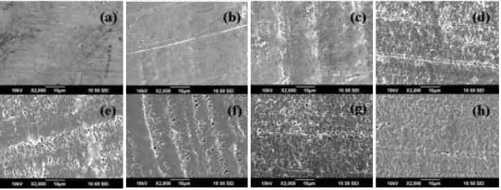
Surface morphologyWe observed the surface morphological changes of the PTFE by varying fluence ranging from 1×10¹⁴to 1×10¹⁷ ions∙cm-2at an energy level of 150 keV. Fig. 1. shows the
SEM images of pristine and Ar++ implanted samples. For pristine sample and implanted sample with fluence of 1× 10¹⁴ions∙cm-2, there was no significant change in the
sur-face morphology. Both samples exhibited plain sursur-face. Above the fluence of 5×10¹⁴ ions∙cm-2, the surface
be-gun to show modified topography. At 5×10¹⁴ions∙cm-2,
the surface exhibited moderately flat appearances with very irregularly placed small-sized pores or dots. As the fluence increased to the value of 5×10¹⁶ions∙cm-2, the
rough-ness was also increased and pore size became more larger. In case of the sample at 5×10¹⁶ ions∙cm-2, the surface
exhibited relatively dark color and showed more distorted or damaged morphology. The surface morphology has been changed with increasing fluence due to chain scission, car-bonization, and/or ion erosion phenomena (Zhang et al. 2002). At 1×10¹⁷ions∙cm-2, the topography of implanted
PTFE sample showed similar surface compared with the sample of the fluence of 5×10¹⁶ions∙cm-2.
Surface chemical composition
XPS analysis was performed to investigate the chemical
Fig. 1. SEM images of pristine PTFE (a) and Ar++implanted PTFE with 1×10¹⁴ions cm-2(b), 5×10¹⁴ions cm-2(c), 1×10¹⁵ions cm-2(d),
composition of the PTFE samples. Table 1 shows the relative intensity of C1s, F1s, and O1s peaks (%) and the F/C and O/C atomic ratios of pristine and implanted sam-ples. The observed data exhibited the increased C1s peak ratio and decreased F1s peak ratio with increasing fluence,
which resulted in the decreased F/C ratio. The value of O/C ratio was, on the whole, increased with increasing fluence. The increased O/C ratio and decreased F/C ratio denote the oxidation and de-fluorination of the surface of implanted PTFE, respectively.
Table 1. The relative intensity of C1s, F1s, and O1s peaks (%) and the F/C and O/C atomic ratios of pristine and ion implanted samples.
Ion fluence 0 1×10¹⁴ 5×10¹⁴ 1×10¹⁵ 5×10¹⁵ 1×10¹⁶ 5×10¹⁶ 1×10¹⁷ (ions∙ cm-2) C1s 36.69 35.98 44.86 50.33 71.61 79.84 81.11 84.48 CF3 bond 1.67 5.51 3.20 CF2 bond 22.41 20.31 15.49 15.37 2.24 CF bond 2.16 2.59 C-C 14.28 8.33 5.73 17.86 46.24 63.73 60.62 69.29 C==C 1.72 2.05 1.92 1.84 C==O 1.30 7.50 5.39 6.38 3.95 4.14 5.25 C-O 2.65 8.58 6.59 14.39 10.32 13.76 9.94 F1s 63.30 61.98 53.04 45.42 15.41 6.27 5.84 2.15 O1s 2.04 2.1 4.24 12.98 13.89 13.07 13.37 [F] / [C] ratio 1.72 1.72 1.18 0.90 0.21 0.08 0.07 0.03 [O] / [C] ratio 0.05 0.05 0.08 0.18 0.17 0.16 0.15 300 298 296 294 292 290 288 286 284 282 280 Intensity (arb. units) Intensity (arb. units) Intensity (arb. units) Intensity (arb. units) Intensity (arb. units) Intensity (arb. units) Intensity (arb. units) Intensity (arb. units)
Binding energy (eV) Binding energy (eV) Binding energy (eV)
Binding energy (eV) Binding energy (eV)
Binding energy (eV) Binding energy (eV)
Binding energy (eV) CF2 (a) C-C 300 298 296 294 292 290 288 286 284 282 280 CF3 CF2 C OC-O C-C C C (b) C C 300 298 296 294 292 290 288 286 284 282 280 CF3 CF2 C O (d) 300 298 296 294 292 290 288 286 284 282 280 CF3 CF2 C O C C (c) 300 298 296 294 292 290 288 286 284 282 280 C C C O (f) 300 298 296 294 292 290 288 286 284 282 280 (e) C O CF CF2 300 298 296 294 292 290 288 286 284 282 280 CF C O (g) 300 298 296 294 292 290 288 286 284 282 280 C O (h) C-O C-C C-C C-O C-C C-O C-C C-O C-O C-C C-O C-C
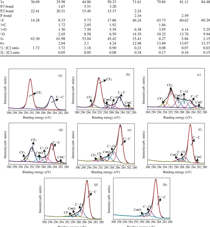
Fig. 2. XPS spectra of C1s for pristine PTFE (a) and Ar++implanted PTFE with 1×10¹⁴ions cm-2(b), 5×10¹⁴ions cm-2(c), 1×10¹⁵ions cm-2(d), 5×10¹⁵ions cm-2(e), 1×10¹⁶ions cm-2(f), 5×10¹⁶ions cm-2(g), and 1×10¹⁷ions cm-2(h).
Fig. 2 shows the XPS spectra of C1s for pristine PTFE and Ar++
implanted PTFE samples with fluence ranging from 1×10¹⁴ions∙cm-2to 1×10¹⁷ions∙cm-2. The C1s
peaks at 292.5 eV for the CF2 bond and at 285 eV for the C-C bond were observed on pristine sample as shown in Fig. 2, and the binding energy difference between two was about 7.5 eV. The arbitrary change in C1s peaks was found due to the variation in intensity of CF3, CF2, CF, C-C, C==C, C-O, and C==O bonds with increasing fluence. De-fluorination, chain-scission, cross-linking, carbonization, and chemical reaction seem to be the main reason for the change of chemical bonds (Koh et al. 1997; Zhang et al. 2002). One can see the formation of C-O bond and the intensified C-C bond with increasing fluence. The forma-tion of C-O bond resulted from the generaforma-tion of free radi-cals due to the electronic excitation (Zhang et al. 2002), which react with oxygen in air when extracting the
implant-ed samples from Target Chamber. And, chain-scission and carbonization seem to be the dominant reason for the increased C-C bond.
Wettability
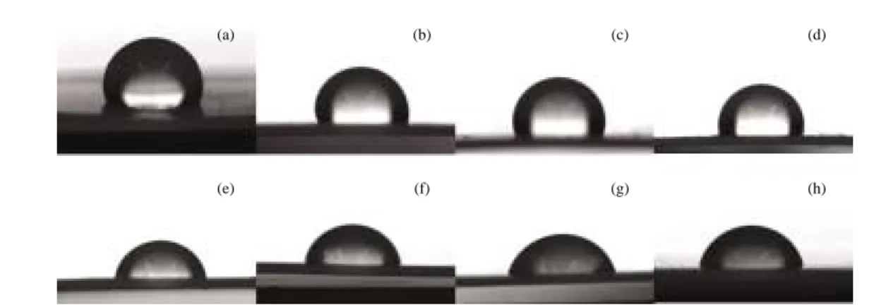
Fig. 3 and 4 show the water droplet images and contact angle values (degree) between the water droplet and the surface of pristine and Ar++
implanted PTFE samples. The water contact angle of pristine PTFE sample was about 111�, and this high contact angle is very special among polymeric materials. It implies that PTFE has a very low surface energy (Kim 2000). With increasing fluence, the water contact angle was decreased to 66�at 5×10¹⁶ions∙ cm-2, and it slightly increased to 73�at 1×10¹⁷ions∙cm-2.
The decrement of contact angle means the surface of implanted PTFE sample becomes more hydrophilic, and the increment of that value denotes that surface of the implant-ed PTFE sample exhibits more hydrophobicity due to the carbonization at the higher fluence.
CONCLUSIONS
Ion implantation technique was applied to PTFE sheets by means of Ar++
ions at an energy level of 150 keV with fluence range from 1×10¹⁴ to 1×10¹⁷ ions∙cm-2. The
SEM images exhibited the discolored and deformed mor-phologies with randomly situated irregular-sized pores, as the fluence increased. For XPS analysis, it appears that due to de-fluorination, chain-scission, cross-linking, carboniza-tion, and chemical reaccarboniza-tion, a variety of phenomena, such as increased O/C ratio, decreased F/C ratio, formation and
Fig. 3. Water droplet images of pristine PTFE (a) and Ar++implanted PTFE with 1×10¹⁴ions cm-2(b), 5×10¹⁴ions cm-2(c), 1×10¹⁵ions cm-2(d), 5×10¹⁵ions cm-2(e), 1×10¹⁶ions cm-2(f), 5×10¹⁶ions cm-2(g), and 1×10¹⁷ions cm-2(h).
Fig. 4. Water contact angle as a function of fluence. 150 140 130 120 110 100 90 80 70 60 50 40 30 Contact angle (degree) 0 1×10¹⁴ 5×10¹⁴ 1×10¹⁵ 5×10¹⁵ 1×10¹⁶ 5×10¹⁶ 1×10¹⁷ Fluence (ions cm-2) (a) (b) (c) (d) (e) (f) (g) (h)
change of C-O bond, and variation of C-C bond, were occurred. With increasing fluence, the water contact angle of PTFE sample was decreased to about 66� at 5×10¹⁶ ions∙cm-2, which denotes the hydrophobicity of PTFE has
changed to the hydrophilicity by means of ion implantation. Additional work is underway to investigate bio-compati-bility of Ar ion implanted PTFE film for artificial blood vessels, cell patterning, cell chips, etc.
REFERENCES
Bai J, Wang T, Li HD, Jiang N and Sakai S. 2001. (0001) Orient-ed GaN epilayer grown on (1120) sapphire by MOCVD. J. of
Cryst. Gro. 231:41-47.
Budzynski P, Youssef AA, Surowiec Z and Paluch R. 2007. Nitrogen ion implantation for improvement of the mech-anical surface properties of aluminium. Vacuum 81:1154-1158.
Colwell JM, Wentrup-Byrne E, Bell JM and Wielunski LS. 2003. A study of the chemical and physical effects of ion implantation of micro-porous and nonporous PTFE. Sur. &
Coat. Tech. 168:216-222.
Dworecki K, Hasegawa J, Sudlitz K, Slezak A and Wasik S. 2001. Modification of electrical properties of polymer membranes by ion implantation(II). Nuc. Instr. & Meth. in
Phy. Res. B 185:61-65.
Guenther M, Gerlach G, Suchaneck G, Schneider D, Wolf B, Deineka A and Jastrabik L. 2004. Physical properties and structure of thin conducting ion-beam modified polymer films. Macromol. Symp. 212:245-250.
Guzman L, Man BY, Miotello A, Adami M and Ossi PM. 2002. Ion beam induced enhanced adhesion of Au films deposited on polytetrafluoroethylene. Thin Solid Films
420-421:565-570.
Ikeyama M, Hayakawa Y, Tazawa M, Nakao S, Saitoh K, Mi-yagawa Y and MiMi-yagawa S. 1996. Changes in surface mo-rphology and optical properties of polymers induced by ion implantation. Thin Solid Films 281-282:529-532.
Jagielski J, Piatkowska A, Aubert P, Thome L, Turos A and Abdul Kader A. 2006. Ion Implantation for surface mod-ification of biomaterials. Sur. & Coat. Tech. 200:6355-6361.
Kane MH, Asghar A, Payne AM, Vestal CR, Zhang ZJ, Strass-burg M, Senawirante J, Dietz N, Summers CJ and Fergu-son IT. 2005. CompariFergu-son of GaMnN epilayers prepared by ion implantation and metalorganic chemical vapor de-position. Phys. stat. sol.(c) 2(7):2441-2445.
Kim SR. 2000. Surface modification of poly (tetrafluoroethy-lene) film by chemical etching, plasma, and ion beam treatments. J. Appl. Polym. Sci. 77:1913-1920.
Koh SK, Park SC, Kim SR, Choi WK, Jung HJ and Pae KD. 1997. Surface modification of polytetrafluoroethylene by Ar++irradiation for improved adhesion to other materials. J. Appl. Polym. Sci. 64:1913-1921.
Liu H, Wang X, Wang L and Tang B. 2007. Rolling contact fatigue and mechanical properties of titanium carbide film synthesized on bearing steel surface. Sur. & Coat. Tech.
201:6606-6610.
Park JW, Sohn CW and Choi BH. 2006. Some characteristics of materials surface-modified by ions beam bombardment.
Cur. Appl. Phy. 6:188-193.
Suzuki Y. 2003. Ion beam modification of polymers for the application of medical devices. Nuc. Instr. & Meth. in Phy.
Res. B 206:501-506.
Yoshinari M, Oda Y, Ueki H and Yokose S. 2001. Immobili-zation of bisphosphonates on surface modified titanium.
Biomater. 22:709-715.
Zhang J, Xu L, Yu X and Liu X. 2002. Influence of aging on the morphology and wettability of polytetrafluoroethylene implanted by high-fluence carbon ion. Mater. Lett. 56:410-417.
Zhang J, Yu X, Li H and Liu X. 2002. Surface modification of polytetrafluoroethylene by nitrogen ion implantation. App.
Surf. Sci. 185:255-261.
Manuscript Received: July 31, 2007 Revision Accepted: August 13, 2007