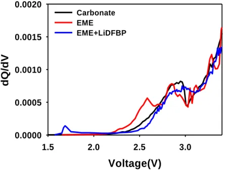
With the advent of the era of electric vehicles, the demand for high energy density lithium-ion batteries with fast charging capacity is increasing. To increase the energy density of lithium-ion batteries, a high level of loading of the electrode is required. It is confirmed through dQ/dV graph that the LiDFBP additive inhibits the degradation of EME and forms a stable film on the surface of the electrodes.
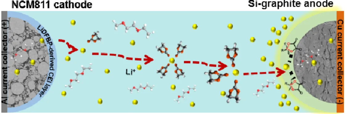
The stable CEI layer formed by degradation of LiDFBP additives prevents dissolution of transition metal ions and microcracking of the NCM811 cathode. During the cycling test, the SEI layer derived from LiDFBP additive suppresses the formation of Li dendrite and byproducts on the surface of the anode. Red dashed lines indicate thick SEI layer caused by electrolyte decomposition on the surface of the graphite anode.
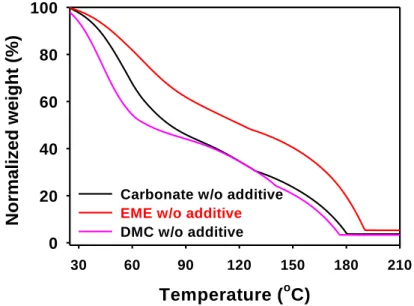
TGA of electrolytes containing only solvents and lithium salts without additives. a) Changes in the thickness of the bag-type full cells stored at 45oC. b) Changes in the thickness of the bag-type full cells stored at 60oC. a) Viscosity (dots and left-side y-axis) and conductivity (bars and right-side y-axis) values for carbonate and EME. Schematic illustration of the effects of LiDFBP-derived CEI on degradation of the NCM811 cathode. a) Schematic illustration of transition metal dissolution test.
Lithium-ion battery
For high capacity of LIBs
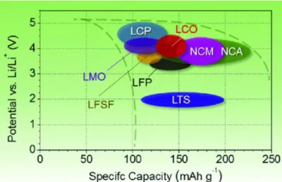
Introduction of Ni-rich cathode
Introduction of Silicon as anode
The anode materials are also main materials for determining the capacity that can accommodate the Li ions from the cathode. 10] For these requirements, graphite has currently become the most suitable material and is widely used as the anode for LIBs. But to realize the greater capacity of the anode materials, there are many attempts to find the substances beyond the graphite (~372mAh/g) such as using Si, Sn, Ge and Sb atoms.
Si anode is one of the most practical anode materials in that the theoretical capacity is ten times higher than graphite (~4200 mAh/g for Li4.4Si versus 372 mAh/g for LiC6). In addition, Silicon has greater affinity between water and HF than graphite, forming an irreversible combination, which also causes loss of Si-active material. The anode material with the composition of Si and graphite can be one way to reduce the side reaction and get the advantages of high capacity.
11] However, many Si issues still remained after repeated cycling and lead to pulverization of the Si alloy and coated silicon, causing repeated surface damage (Figure 7). The stable SEI layer that tolerates Si volumetric strain and prevents electrolyte decomposition improves the cycle life of LIBs.
![Figure 6. Candidates of active anode materials for the post lithium batteries. [10]](https://thumb-ap.123doks.com/thumbv2/123dokinfo/10496891.0/17.892.116.775.127.501/figure-candidates-active-anode-materials-post-lithium-batteries.webp)
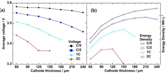
High-mass-loading electrode
Improvement strategies with electrolyte
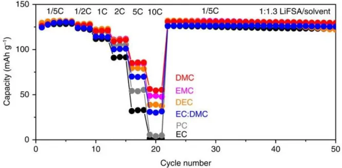
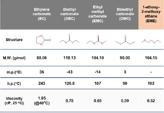
Solvent with low viscosity
SEI and CEI forming additives
In the case of cathode, the protective cathode electrolyte interphase (CEI) layer must be formed to prevent side reactions with residual lithium, highly oxidative Ni4+ and electrolyte on the surface. In addition, the well-formed CEI layer can effectively prevent structural deformation of Ni-rich cathode during cycling and mitigate the further formation of microcracks. LiDFBP additive forms P-O-based uniform SEI on the anode and cathode due to its lowest lowest unoccupied molecular orbital (LUMO) and high highest occupied molecular orbital (HOMO).
Likewise, additives with low LUMO are favorable for reductive decomposition at the anode, which readily obtains the electrons. In addition, polar parts (B-O, P-O, S=O) of additives form ionically conductive SEI, which increases the rate capacity of the battery. 27] To increase the fast charging capability of Li-ion batteries, the formation of low-resistive and ion-conducting SEI is critical.
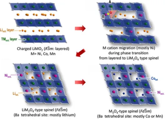
LiDFBP-derived CEI also prevents HF attack and facilitates cathode phase transition ( Figure 14 ).
Functional electrolyte design for fast charging capability
EXPERIMENTAL
Electrochemical measurements
After the aging process, 1 h at 45 °C and 20 h at 25 °C, the electrochemical performance of the full cells was performed on a computer-controlled battery testing equipment (WonATech WBCS 3000). Li/Li+ at 25oC at a fixed C rate (C/10), then the constant voltage was applied until the current was below C/20. Stability of electrolyte on the cathode was investigated by a floating test at 25oC, in which 2032 coin-type NCM811/Li half-cells were charged to 4.3V at a constant current of C/10 and 4.3V was applied for 10 hours at a constant voltage wise.
The NCM cathode in the half cell was fabricated at a low loading level of 10.2 mg/cm2 to prevent polarization during charging. The anodic stability of the electrolytes was determined by linear sweep voltammetry (LSV) with Li foil at a constant scan rate of 0.5 mV s –1 in the voltage range 3.0 V-5.5 V (vs. Li/ Li+) at 25oC. To measure fast charge cycle performance, the full cells were tested between 2.5V and 4.2V at 45oC with a fixed charge C rate (4C) and discharge C rate (1C).
In addition, cells used for charge rate performance experiments were cycled at 25 °C at a fixed C discharge rate (C/10) and various C charge rates (C/2, 1C, 2C, 3C, C/2). All electrodes are dried in a vacuum oven for more than 10 hours at 110oC before assembling the bag. After the aging process, the bag-type solid cells were pretreated twice between 2.5 V and 4.2 V at 25 °C at a current of C/10.
At the first cycle of pre-cycle, after 2 hours of charging, stop charging and cut off the gas space in the bag cell to degas the cell with degraded electrolyte forming SEI layer. After sealing the bag with vacuum sealing machine (AZC-010, airzero, INTRISE), the remaining pre-cycle process continued.
Characterization
The introduction of low viscosity solvent EME leads to lower interfacial resistance than carbonate. The visible splitting of the peaks means that the NCM811 cathode loaded with EME is more disconnected than the one with carbonate. The EME electrolyte exhibits a superior delithiation ability than the carbonate electrolyte, enabling easy diffusion of lithium ions into the main cathode particles.
In addition, the LiDFBP effectively improves anodic stability of the electrolyte containing EME solvent at high temperature as shown in Figure 28 . Because low viscosity of EME solvent allowed easy delithiation, the first discharge capacity of the full cell with EME is higher than Carbonate. Thus, the increase of the C-F peak intensity indicates that LiDFBP prevents the electrolyte decomposition and forms a thin surface film.
In other words, the increase in C-F peak intensity is because the thin surface film formed by the LiDFBP additive does not block the F signal from the cathode, unlike EME. In the case of the cathode, the peak intensity of NiF2 is lower than that of EME, because the LiDFBP-derived CEI layer hinders the initiation of microcracks (Figure 33d). Consequently, LiDFBP improved the cycle retention of the whole cells with EME + LiDFBP at high temperature. a) Schematic representation of the transition metal dissolution test.
The result shows that the SEI layer formed by the EME electrolyte could not protect the cathode from HF attack, which corresponds to the transition metal test result. LiDFBP successfully protects the anode from HF attack and prevents the dissolution of the metal ions of the NCM cathode. Cross-sectional images of the cycled gra-SiC anode with EME + LiDFBP reveal that the SEI layer obtained from LiDFBP is thin and uniform even after 50 cycles at 45 °C (Figure 35f).
In C 1s spectra, the anodes with EME appear to have a remarkable reduction in the peak intensity assigned to C-C, compared to the anode with carbonate (Figure 36a, d). This finding is consistent with the cross-sectional SEM images of the anode cycled with EME + LiDFBP (Figure 35f). XRD data of the NCM811 cathode after charging at a rate of 4C reveals facile delithiation in the EME electrolyte.
Ni 2p spectra of the cycled anode reveal reduced NiF2 deposition on the anode. Logan, E.R., et al., A study of the physical properties of lithium-ion battery electrolytes containing esters.
RESULTS AND DISCUSSION
Introduction of LiDFBP additive to complement EME solvent
In addition, the NCM811 cathode with EME + LiDFBP reveals an increase in the peak intensity assigned to C-F at 687.7 eV relative to the cathode with EME. The decrease in peak intensity indicates that CEI derived from LiDFBP prevents oxidation of the LiPF6 salt at the cathode and HF attack. To confirm whether the addition of LiDFBP protects NCM811 cathodes during cycling, SEM analysis of NCM811 cathodes after 50 cycles at 45oC was performed.
During rapid charging at a rate of 4C, microcracks propagate within secondary NCM811 particles as the layered structure of the cathode undergoes drastic volume changes. For verification of the manifestation of the influence of EME and LiDFBP on the transition metal solution, charged NCM811 cathodes were immersed in the various electrolytes after formation cycles and stored at 45oC for 7 days (Figure 33a). Unfolding of the active material caused by HF attack exposes strongly oxidizing Ni4+ to the electrolyte.
This finding indicates that the cathode surface chemistry modified by LiDFBP improves thermal stability to prevent oxidation of electrolyte and HF-induced dissolution of metal ions. Thus, the decrease in C-C peak intensity indicates that the SEI layer formed by EME electrolyte is thick. On the other hand, with EME + LiDFBP electrolyte, the peak intensity assigned to C-C is the lowest among three electrolytes.
37] On the other hand, using LiDFBP additive reduces the peak intensity of resistive LiF and NiF2. In the O 1s spectra, with EME electrolyte, the peak intensity of lithium alkoxide (ROLi) is the highest among three electrolytes (Figure 34c). After 50 cycles of 4C charge and 1C discharge at 45oC, the surface of the gra-SiC anode was observed to identify the deterioration of the particles in each electrolyte composition.
The decrease in the intensity of the C-C peak is due to the thick SEI layer formed by the EME electrolyte during the cycling test. On the other hand, with the EME + LiDFBP electrolyte, the peak intensity assigned to C-C is the highest among the three electrolytes as shown in Figure 36g. LiDFBP successfully protects the anode from HF attack and prevented the dissolution of the metal ions of the NCM cathode during the cycling test.
With EME electrolyte, the peak intensity of ROLi is the highest among three electrolytes (Figure 36f). In addition, the increased ROLi peak also indicates the formation of dendritic Li, which is in good agreement with the SEM image of the cycle anode with EME (Figure 35b).
CONCLUSION
![Figure 7. The regarding problems with using Si as anode. [12]](https://thumb-ap.123doks.com/thumbv2/123dokinfo/10496891.0/17.892.120.787.597.1029/figure-7-regarding-problems-using-si-anode-12.webp)
![Figure 14. Schematic diagram showing the effect of LiDFBP on Li-rich cathode. [26]](https://thumb-ap.123doks.com/thumbv2/123dokinfo/10496891.0/24.892.140.765.576.946/figure-schematic-diagram-showing-effect-lidfbp-rich-cathode.webp)