저작자표시-비영리-변경금지 2.0 대한민국 이용자는 아래의 조건을 따르는 경우에 한하여 자유롭게
l 이 저작물을 복제, 배포, 전송, 전시, 공연 및 방송할 수 있습니다. 다음과 같은 조건을 따라야 합니다:
l 귀하는, 이 저작물의 재이용이나 배포의 경우, 이 저작물에 적용된 이용허락조건 을 명확하게 나타내어야 합니다.
l 저작권자로부터 별도의 허가를 받으면 이러한 조건들은 적용되지 않습니다.
저작권법에 따른 이용자의 권리는 위의 내용에 의하여 영향을 받지 않습니다. 이것은 이용허락규약(Legal Code)을 이해하기 쉽게 요약한 것입니다.
Disclaimer
저작자표시. 귀하는 원저작자를 표시하여야 합니다.
비영리. 귀하는 이 저작물을 영리 목적으로 이용할 수 없습니다.
변경금지. 귀하는 이 저작물을 개작, 변형 또는 가공할 수 없습니다.
공학박사 학위 논문
쿼드로터 무인항공기를 위한 하드웨어 루프 시뮬레이션 연구
HARDWARE IN THE LOOP SIMULATION FOR A QUADROTOR UNMANNED AERIAL VEHICLE
울산대학교 대학원 기계공학과 항공우주공학전공
NGUYEN DANG KHOA
[UCI]I804:48009-200000103310 [UCI]I804:48009-200000103310
HARDWARE IN THE LOOP SIMULATION FOR A QUADROTOR UNMANNED AERIAL VEHICLE
A thesis submitted in partial fulfillment of the requirement for the Degree of
Doctor of Philosophy to the Department of Aerospace Engineering, University of Ulsan, Korea
By
NGUYEN DANG KHOA
May 2018
쿼드로터 무인항공기를 위한 하드웨어 루프 시뮬레이션 연구
HARDWARE IN THE LOOP SIMULATION FOR A QUADROTOR UNMANNED AERIAL VEHICLE
지도교수 하철근
이논문을 공학박사 학위 논문으로 제출함 2018 년 5 월
울산대학교 대학원
기계공학과 항공우주공학전공
HARDWARE IN THE LOOP SIMULATION FOR A QUADROTOR UNMANNED AERIAL VEHICLE
This certifies that the dissertation of NGUYEN DANG KHOA is approved by
Committee Chairman: Prof. SHIN JICHUL
Committee Member: Dr. CHOI HYOUNG SIK
Committee Member: Dr. JANG JONG TAI
Committee Member: Dr. SIBOK YU
Committee Member: Prof. HA CHEOL KEUN
Department of Aerospace Engineering University of Ulsan, Korea
May 2018
NGUYEN DANG KHOA
( )
( )
( )
( )
( )
2018년 5월
i
Acknowledgements
I would like to express my appreciation to my advisor, Prof. Ha Cheolkeun, for his guidance, advice and support during my study in University of Ulsan. All of my works in this dissertation cannot be accomplished without his support.
I would also like to thank to Prof. Shin, Jichul, Dr. Choi, Hyoung Sik, Dr. Jang, Jong Tai, and Dr.
Yu, Sibok for serving on my graduate committee and providing suggestions and comments throughout this thesis.
I would like to thank Dr. Dinh Quang Truong for his help, guidance and co-working during the time I study in University of Ulsan. I also would like to thank my friends, my colleagues, all members of FDCL Lab., for their help, guidance, and co-working during the time I study in University of Ulsan.
Above all, I would like to express my love to my parents, my sister, my wife and my son. Thank you for everything!
Ulsan, May 2018 Nguyen Dang Khoa
ii
Contents
Acknowledgements ... i
Contents ... ii
List of figures ... v
List of tables ... viii
Abbreviations ... ix
Abstract ... x
Chapter 1. INTRODUCTION ... 1
1.1 Overview ... 1
1.2 Scope of dissertation ... 5
1.3 Limitation of dissertation ... 6
1.4 Dissertation outline ... 7
Chapter 2. THEORY AND BACKGROUND ... 8
2.1 Quad-rotor UAV model... 8
2.2 Pixhawk hardware and PX4 source ... 10
2.3 Raspberry hardware ... 14
2.4 Gazebo simulation... 15
2.5 Overview of hardware in the loop simulation ... 17
Chapter 3. DEVELOPMENT OF HILS BASED ON PIXHAWK, GAZEBO AND ... 20
CONTROL APPLICATION SOFTWARE ... 20
3.1 Introduction ... 20
3.2 HILS design ... 22
3.2.1 Design of simulation software ... 23
3.2.2 Development of Pixhawk ... 29
3.2.3 Design of Control application software ... 30
iii
3.3 Implementation of HILS and its result ... 33
3.4 Chapter summary ... 43
Chapter 4. SYNCHRONIZATION CONTROLLER FOR QUAD-ROTOR UAV ... 44
4.1 Introduction... 44
4.2 Control design ... 45
4.2.1 Actuator controller ... 46
4.2.2 Actuator synchronization controller ... 48
4.3 Numerical simulation ... 52
4.4 Extension synchronization controller for 3-RRR parallel robot ... 59
4.5 Chapter summary ... 62
Chapter 5. GENERAL HILS FOR VISON APPLICATION ... 64
5.1 Introduction... 64
5.2 Development of general HILS ... 65
5.3 Software development ... 66
5.4 Hardware development... 67
5.5 Implementation of HILS and results ... 69
5.6 Chapter summary ... 71
Chapter 6. DEVELOPMENT OF SLAM BASED ON HILS CONFIGURATION ... 73
6.1 Graph-SLAM and Selection method Graph-SLAM ... 73
6.2 Development of HILS and Graph-SLAM ... 77
6.3 Simulation result ... 78
6.4 Experimental result ... 82
6.5 Chapter summary ... 86
Chapter 7. CONCLUSIONS AND FUTURE WORKS ... 87
7.1 Conclusions... 87
iv 7.2 Future works ... 88 LIST OF PUBLICATIONS ... 89 REFERENCES ... 90
v
List of figures
Fig. 2.1 Description of the quad-rotor UAV ... 8
Fig. 2.2 Website and list source of PX4 ... 11
Fig. 2.3 Some type of robot using PX4 ... 12
Fig. 2.4 Diagram of PX4 program ... 13
Fig. 2.5 Flowchart describing PX4 structure ... 13
Fig. 2.6 Raspberry Pi 3 board ... 14
Fig. 2.7 Components of the gazebo software ... 15
Fig. 2.8 User interface in gazebo ... 16
Fig. 2.9 Components of the gazebo software ... 16
Fig. 2.10 A displayed world file in gazebo... 17
Fig. 2.11 A UAV development process ... 18
Fig. 2.12 A scheme of SITL development ... 19
Fig. 2.13 A schema of HILS development ... 19
Fig. 3.1 Component schema of HILS ... 23
Fig. 3.2 Description of the SDF file ... 24
Fig. 3.3 Visualization of the quad-rotor UAV ... 24
Fig. 3.4 Flowchart describing the send/receive task between the plugins in Gazebo ... 27
Fig. 3.5 Visualization of the world file in the Gazebo software ... 28
Fig. 3.6 Block diagram of a tracking controller for the quad-rotor UAV ... 29
Fig. 3.7 Compiling and uploading the firmware to Pixhawk ... 30
Fig. 3.8 Structure of the CAS ... 31
Fig. 3.9 GUI of the CAS ... 32
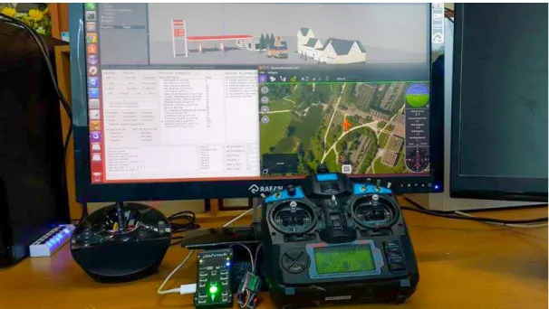
Fig. 3.10 Layout of the overall HILS ... 33
Fig. 3.11 HILS configuration ... 34
vi
Fig. 3.12 Workspace of the quad-rotor UAV in Gazebo ... 35
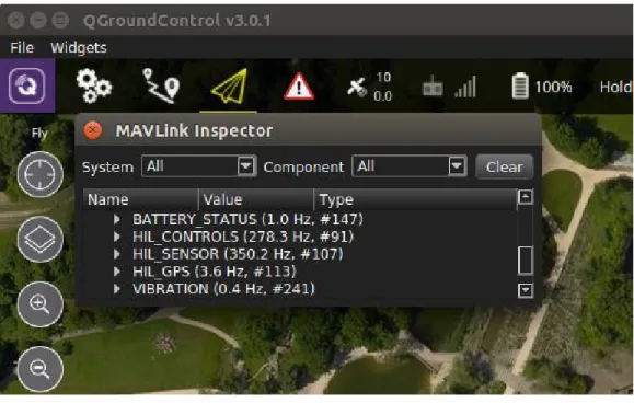
Fig. 3.13 Frequency in QGroundControl ... 36
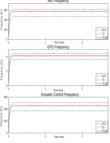
Fig. 3.14 Analysis frequency in QGroundControl ... 37
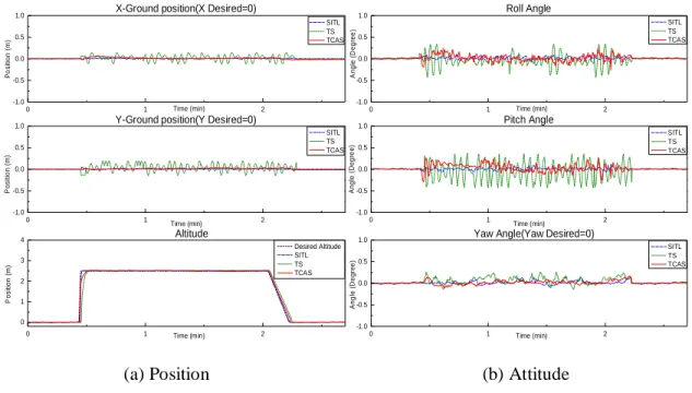
Fig. 3.15 Response of quad-rotor UAV ... 39
Fig. 3.16 Schema of a tracking controller for the quad-rotor UAV in the manual flight mode ... 39
Fig. 3.17 Attitude and altitude of the quad-rotor UAV in the manual mode... 41
Fig. 3.18 Attitude, altitude and tracking waypoint of quad-rotor UAV in the mission flight mode ... 42
Fig. 4.1 Proposed control schema of the quad-rotor UAV ... 46
Fig. 4.2 Structure of PIDNNC ... 48
Fig. 4.3 Schema control configuration for simulation ... 54
Fig. 4.4 Diagram disturbance generation for the quad-rotor UAV ... 55
Fig. 4.5 Response of the quad-rotor UAV without disturbance using different control ... 57
Fig. 4.6 Response of the quad-rotor UAV with disturbance using different control ... 58
Fig. 4.7 3D view the position of the quad-rotor UAV using different control ... 59
Fig. 4.8 Configuration of 3-RRR parallel robot... 59
Fig. 4.9 Disturbance generation for 3-RRR parallel robot ... 60
Fig. 4.10 Response of 3-RRR parallel robot without disturbance using the difference controllers ... 61
Fig. 4.11 Response of 3-RRR parallel robot with disturbance using the difference controllers .. 62
Fig. 5.1 Proposed HILS system for vision application ... 66
Fig. 5.2 Camera module and Raspberry board ... 67
Fig. 5.3 Schema trackingflight controller of the quad-rotor UAV ... 67
Fig. 5.4 Standalone system of the raspberry board ... 68
Fig. 5.5 Full HILS setup ... 69
vii
Fig. 5.6 Workspace of the quad-rotor UAV in gazebo software ... 69
Fig. 5.7 Responses from the quad-rotor UAV ... 70
Fig. 5.8 Raspberry board recognizes the marker pad by using the vision algorithm ... 71
Fig. 5.9 Responses from the quad-rotor UAV in the landing task ... 72
Fig. 5.10 Quad-rotor UAV landing to the marker pad ... 72
Fig. 6.1 Schema of Graph-SLAM process ... 74
Fig. 6.2 Graphical of Graph-SLAM ... 75
Fig. 6.3 Schema connection of HILS for the Graph-SLAM ... 77
Fig. 6.4 3D display world file in gazebo software for HILS ... 78
Fig. 6.5 Cross section of the map under 1[m]... 78
Fig. 6.6 Ranger of the Kinect ... 79
Fig. 6.7 3D mapping of the quad-rotor UAV simulate in HILS system without the optimization ... 80
Fig. 6.8 3D mapping of the quad-rotor UAV simulate in HILS system with the optimization ... 80
Fig. 6.9 Cross section of the quad-rotor UAV in two modes ... 81
Fig. 6.10 2D position of the quad-rotor UAV simulate in HILS system ... 81
Fig. 6.11 Graph-SLAM on the realistic quad-rotor UAV ... 82
Fig. 6.12 FDCL lab room - UOU for the working environment ... 83
Fig. 6.13 3D mapping and position of the quad-rotor UAV... 85
viii
List of tables
Table 2.1 Survey Autopilots for UAV ... 10
Table 3.1 Parameters Gaussian noise for IMU and GPS sensors ... 26
Table 3.2 List softwares use in the proposed HILS ... 30
Table 3.3 Setting frequency for the signal in HILS ... 34
Table 3.4 Frequency and ratio errors in simulations ... 38
Table 3.5 RMS error for the performance of quad-rotor UAV ... 38
Table 4.1 Setting parameters for the quad-rotor UAV ... 54
Table 4.2 Simulation test case for the quad-rotor UAV ... 55
Table 6.1 Comparison of SLAM algorithms[85] ... 74
ix
Abbreviations
HILS Hardware In the Loop Simulation
SITL Software In The loop Simulation
PID Proportional–Integral–Derivative
DOF Degree Of Freedom
SLAM Simultaneous Localization And Mapping
RANSAC Random Sample Consensus
ICP Iterative Closest Point
SIFT Scale Invariant Feature Transform
SURF Speeded Up Robust features
EKF Extended Kalman Filter
x
Abstract
The Unmanned Aerial Vehicles (UAVs) have been well-known as an automatic robot helping people carry out the hard and dangerous works. In the platform configuration, the UAV can be mainly classified into three categories, the fixed-wing types, the helicopter types and the multi-rotor types. The strength of FW types is high speed flight and fuel efficiency. However, it cannot perform to vertical takeoff and landing(VTOL) and hover in the flight itinerary. In the opposite points of view, the helicopter and multi-rotor types can provide the limitation on FW types. By outstanding features of VTOL, a quad-rotor UAV is chosen and used to demonstrate the contribution of this thesis. The main content of this thesis presents the hardware in the loop simulation (HILS) in which the speed communication of the components of HILS is ensure and its can use to simulate the complex flight algorithm and application algorithm such as the vision and the SLAM. Furthermore, a synchronization controller is proposed to improve the performance of the quad-rotor UAV in the tracking trajectory.
Firstly, a simulation based on the hardware in the loop is developed for UAV. The HILS includes the pixhawk hardware, gazebo and a middleware software. Therein, the pixhawk is installed a development flight control algorithm by using the PX4 open source. The gazebo is presented the 6DOF, sensor models, 3D visualization and environment. The middle software named the control application software (CAS) is robustly designed to secure communications in the HILS system by using the multithread architecture in Qt Creator, which can to synchronize signals, accelerate time responses and reduce signal losses of the communication between the Gazebo and Pixhawk. Furthermore, the CAS can create line connections to any software and hardware by using TCP, UDP and serial protocol. The CAS provides a GUI that allows users to monitor the status of packet transfer and perform the tasks of a ground control station(GCS) software.
xi Secondly, an accurate tracking controller is proposed for the quad-rotor UAV. By using the modify controller installed on Pixhawk , the angular velocity of each actuator is generated.
Hence, a synchronization controller includes the four sliding mode controllers (SMC) to drive velocity actuators and a supervisory controller consists four PID-neural network controllers (PIDNNC) to compensate the synchronization errors between the actuators due to system nonlinearities, uncertainties and external disturbances. The proposed controller can support not only the quad-rotor UAV tracking trajectory but also the 3-RRR parallel manipulator tracking.
Lastly, the HILS is extended for the vision applications. For beginning, the camera model is added more to the gazebo to measure the observation environment from the quad-rotor UAV.
Next, the raspberry board based Linux OS is put more to HILS setup to perform the vision algorithm. The autonomous landing is applied for the quad-rotor UAV based on the estimate position from the vision algorithm. For advance application of the vision, the graph-SLAM algorithm is developed on the raspberry board. By using the RGB-D camera model on the gazebo like the real Kinect camera, the HILS can demonstrate the SLAM problem which simultaneously localization and mapping for the quad-rotor UAV.
1
Chapter 1. INTRODUCTION
1.1 Overview
In the unmanned systems community, UAVs are becoming more and more popular in the agriculture, transportation, navigation and military fields. There are many types of UAVs, including fixed-wing [1], quad-rotor [2], hexacopter [3] and helicopter [4]. Among them, the quad-rotor UAV attracts significant interest from researchers due to its advanced characteristics such as simple structure, easy assembly and potential to hover, take-off and land in small areas.
Prior to the real flight of the UAV, quad-rotor UAV simulations need to be performed to reduce the risk of property damage resulting due to airframe crashes, system failure or controller malfunction. In order to prevent these problems from occurring, HILS is an excellent solution to test the UAVs system on a real-time platform, combining a hardware device with simulation software. The hardware is used to install control algorithms on the microchip, while a simulation software provides the nonlinear 6DOF model of UAVs, sensor models, environment models and visualization to simulate the UAV operation.
Some hardware, such as the AuRoRa board-STM32F3Discovery board [5], PhycoreMPC5200B-tiny embedded board [6], dSpace dsll03 board [7], Rabbit board [8] and FPGA microchip [9], were chosen to develop HILS for UAVs. Although these boards provided the real-time platform, these solutions are limited due to the complicated hardware components, which are inflexible, expensive and difficult to establish for various simulations.
In recent years, the Pixhawk hardware [10,11] has been widely used for UAV applications.
It provides high-end autopilot hardware with low costs and high availability. Furthermore, the control algorithms in the open-source code PX4 [12,13], which is autopilot firmware used to drive unmanned aerial and ground vehicles, can be installed on this hardware.
2 Pixhawk can be coupled with some simulation software to establish the HILS system. The jMAVSim[14] has been used to develop HILS for a multi-rotor UAV simulation. However, it has limitations with regard to complex model. Researchers have thus used other simulation software such as MAV3DSim [15], GEFS [16], FlightGear [17] and Xplane [18]. Although they provide a simulation framework, such software still requires significant amount of effort when testing sensor-based high level control [19]. The cost of the commercial simulators needs to be considered in the development process.
To overcome these limitations, the Gazebo software [20] is popular in the robotics community and is completely open-source, so that the user can easily define 3D virtual worlds, sensor models and communication protocols. In particular, this software contains the open dynamics engine(ODE), which can present a system model robot with high accuracy in real-time conditions [21]. ODE can provide real-time dynamical simulations and the corresponding sensor readings for the UAVs [22,23].
In the traditional HILS setup, the algorithm installed on the hardware is connected to a 6DOF model on the simulation software via either a direct connection or using middleware software. In the first case, the parts of HILS are connected without any information regarding the state of line transfer within the HILS system [14,17,18]. Subsequently, the communication of HILS is conflicted, the time responses are slow and the signals between the hardware and simulation software are lost. Therefore, the HILS performance is totally deteriorated. In the second case, the middleware software robot operating system (ROS) can be used to overcome the limitations of the first case [22,24]. To achieve this, the ROS needs to integrate all parts of the HILS, including the hardware and software. Before transferring a signal to another part, the data need to be attached to an ROS message. Consequently, the HILS system becomes more
3 complex, limiting its applicability. Therefore, a middle software named control application software (CAS) is developed in this thesis to overcome the limitation of the previous researches.
For design controller using the traditional approach, the position control and attitude control were applied for the quad-rotor UAV based on the measurement of sensors such as global positioning system (GPS) and inertial measurement unit (IMU). Several control solutions have been known as the PID controller [25,26], Fuzzy-PID [27,28], extended state observer [29], back-stepping-based PID nonlinear control [30], sliding mode control [31], LQR control [32], Adaptive Super Twisting Control [33].
Although the developed control systems showed some interesting results, their applicability is limited due to all output controller generate the velocities which are setup to the actuators though a electric speed controller (ESC) without any sensor for feedback. Therefore, the actuator could not track the speed desired with the high accurately. The performance of the quad-rotor UAV is totally deteriorated.
To overcome the shortcomings of the traditional control approaches, the velocity measurement sensor was attached to the actuator of the quad-rotor UAV to create a closed loop system with the velocity controller. Chan et al. [34] used infrared sensor (IR) and Gonzalez et al.
[35] used reflex speed sensor as a feedback sensor.
Although the efficiency of using the sensor and the control method in these studies was well presented by both the simulation and real experiments. Nevertheless, each actuator in the quad-rotor UAV uses independently controlled without any communication with others.
Subsequently, any error of the actuator could lead to degraded of the quad-rotor UAV. Hence, the synchronization controller is indispensable to compensate the error between the actuators, but it has not been stated. This thesis will present a synchronization controller to solve the problem which comes from the system nonlinearities, uncertainties and external disturbances.
4 The quad-rotor UAV is very useful to help people carry out the hard and dangerous works.
Their applications attracted significant interests of researchers [36,37]. Specially, the vision application was presented exciting, such as tracking a ground moving target [38], autonomous landing on a moving unmanned ground vehicle (UGV) [39], 3D mapping [40]. In these studies, the researchers used the realistic UAV for demonstrating their applications. The testing process may have high risk of property damage. To restrict the accidents and safety for human, the HILS is often performed for the UAVs system on the real time platform.
For some research associated with vision in HILS, the real camera is used to estimate the state of UAV based on the virtual image which is shown on the desktop monitor screen [41,42], projector screen [43,44]. Although the developed HILS systems showed some interesting results, their applicability is limited due to the cost and associated complicated components of the camera. Beside, the presented 3D information of scene is also the trouble of using the virtual image on the screen.
In another approach, the gazebo software [45] was utilized to simulate the 6DOF model of the UAV, virtual camera and virtual 3D environment workspace for the simulation. For example, Odelga el at. [46] combined the Odroid board with the gazebo to present the operation of the UAV. Therein, the hardware board is installed for the flight control algorithm and the vision control algorithm. In this case, the hardware system may overload because the operating system(OS) must perform many processes at the same time. And the Odroid board lacks the basic sensor for a UAV such as IMU sensor, GPS sensor, and etc. Therefore, the real UAV needs to equip these sensors to provide state of UAV for the flight controllers. Consequently, the system becomes complex, and needs expensive solution. As another solution, the pixhawk was used to setup the flight control algorithm, which is integrated with the full sensor for a quad-rotor UAV [24]. In this study, the vision algorithms were performed on the a desktop computer which
5 is difficult to apply to the real UAV because the weight of desktop computer is too heavy to integrate on the UAV. Therefore, in this thesis presents a better solution for the vision applications in the HILS configuration. Herein, the autonomous landing and the Graph-SLAM based on the virtual camera in the HILS system are performed to demonstrate the effectiveness of the HILS configuration as well as the Graph-SLAM.
1.2 Scope of dissertation
This thesis has been focused on following motivations: the tracking trajectory performance of the quad-rotor UAV and the hardware in the loop simulation (HILS) for a quad- rotor UAV. For HILS development, the speed transfer and the quality of packet are considered.
Some application of HILS in development the vision algorithm, SLAM algorithm are also mentioned. The specific subjects in this dissertation are as follows:
Firstly, a middleware software called the control application software (CAS) is designed to secure communications in the HILS system. Unlike the ROS, the CAS does not need to integrate the different HILS components. For configuration, three components are used to verify the performance of the CAS. First, the Gazebo software is used to construct the nonlinear 6DOF model and 3D visualization of the quad-rotor UAV based on 3D CAD model from the SolidWorks software. The sensor models are integrated with the Gazebo software through the plugins. Second, the flight control algorithm for the quad-rotor UAV is designed and implemented on Pixhawk by using the open-source code PX4. Third, the CAS is robustly developed with a multithread structure in Qt Creator to synchronize signals, accelerate time responses and reduce signal losses of the communication between the Gazebo and Pixhawk.
Furthermore, the CAS can create line connections to any software and hardware by using TCP, UDP and serial protocol. Therefore it does not need to integrate the parts of HILS as the ROS.
6 The CAS provides a GUI that allows users to monitor the status of packet transfer and perform the tasks of a ground control station(GCS) software.
Secondly, to improve the accuracy of the actuator controller for the quad-rotor UAV, a SYNC control approach is designed for stability attitude control of a quad-rotor UAV. Herein, the sliding mode controller (SMC) is designed to keep the each actuator to track its desired velocity. And the PID-based neural network controller (PIDNNC) is robustly constructed using Lyapunov stability condition to compensate the sync errors between the actuators due to the system nonlinearities, uncertainties and external disturbances. The sync errors therefore can converge simultaneously to zero to ensure the robust performance of the quad-rotor UAV.
Finally, HILS is the important part in the robot development. It can avoid the damage caused by the algorithm, the hardware design and the environment. However, the vision test based HILS has been troubled because the limitation of the simulation software in which the camera sensor model could not present more detail the visualization of the robot view. Recently, the gazebo simulation software provided the libraries for extending the camera sensor model.
Therefore, the vision application for HILS is easy to develop. A general HILS is built for testing the flight control algorithm and vision algorithm of the quad-rotor UAV on the real-time condition. Herein, the vision algorithm is installed on the raspberry board to estimate the position of the quad-rotor UAV for autonomous landing. In addition, the Graph-SLAM algorithm is applied to the raspberry board to demonstrate the capability of the HILS development, is performed in both simulation and experiment to verify the performance of the Graph-SLAM algorithm.
1.3 Limitation of dissertation
This study presented the HILS configuration and improves its performance. To accurate trajectory tracking the position of the quad-rotor UAV, the synchronization controller is
7 proposed based on the SMC and PIDNNC controller to compensate the error between the actuator in the quad-rotor UAV configuration. However, this thesis has some limitation as follows:
Synchronization and verifying between HILS and realistic flight are not performed to improve the HILS configuration.
The synchronization controller are not applied on the real actuator. However, this controller was performed based on the real time process and complex condition.
Therefore, it can easy apply to real the quad-rotor UAV.
1.4 Dissertation outline
The structure of the dissertation begins with overview introduction in Chapter 1. The theory and background is presented in the Chapter 2. Chapter 3 presents the hardware in the loop simulation (HILS) with a optimization the structure and the quality of signal in the system by development a middle ware named control application software. Based on the HILS configuration, Chapter 4 presents the new synchronization controller for the actuator of the quad- rotor UAV by using the sliding mode controller and the PID-neural network controller. In Chapter 5, the HILS is developed under the flight control and the vision process for the land process to a marker which is perform by the pixhawk and the raspberry board. For a complex vision application, the Graph-SLAM and HILS are presented in Chapter 6. Finally, conclusion and future works are performed in Chapter 7.
8
Chapter 2. THEORY AND BACKGROUND
This chapter provides the theoretical basics, the hardwares and the softwares to understand the content of this thesis. The quad-rotor UAV is chosen as object research, which is presented the description, control input and the dynamic model. Based on the selection UAV, the hardwares and software as the pixhawk, raspberry and gazebo are described to build the hardware in the loop simulation (HILS). At the end of this section, the overview HILS are presented to realize the importance work in the UAV development process.
2.1 Quad-rotor UAV model
In this thesis, a quad-rotor UAV, which is shown in Fig. 2.1, is used for HILS development. The UAV contains a body frame that is connected with four electric motors. Let's use motors 1 and 3 as rotating in the clockwise direction. Similarly, motors 2 and 4 are set to rotate in the counter-clockwise direction. l1 and l2 are the distances along the axes to UAV's center gravity.
(a) IRIS quad-rotor UAV (b) Geometry of the quad-rotor UAV Fig. 2.1 Description of the quad-rotor UAV
The quad-rotor UAV is controlled by the angular velocity of the four motors. Each motor produces forces and moments in the direction of the motor axis. Let's define Fi,Mi (i=1,2,3,4) to be the force and moment of the ith motor, respectively. These can be defined as:
9
2
i f i
F K
(2.1)2
i m i
M K (2.2)
where i is the angular velocity of the ith motor; Kf and Km are constant values of rotor thrust coefficient and rotor torque coefficient, respectively.
Suppose that the control inputs (U1, U2, U3 and U4) of the quad-rotor UAV are defined as follows:
2
1 1
2
1 1 1 1
2 2
2
2 2 2 2
3 3
2
4 4
f f f f
f f f f
f f f f
m m m m
K K K K
U
l K l K l K l K
U
l K l K l K l K
U
K K K K
U
(2.3)
Based on these control inputs, the motion of the quad-rotor UAV can be divided into two subsystems, rotational subsystem roll
, pitch
and yaw
and translational subsystem
x y z, ,
. The dynamic model of the quad-rotor UAV can be implemented as [47].
2
3
4
1
1
1
1 1 1
r r yy zz
xx
r r zz xx
yy
xx yy
zz
U J I I
I
U J I I
I
U I I
I
x cos cos sin sin sin U
m
y cos sin sin sin cos U
m
z cos cos U g
m
(2.4)
10 where r 1234; Ixx,Iyy,Izz are the moments of inertia about the principle axes in the body frame; Jr denotes the inertia of the motor; m is the total mass of quad-rotor UAV and g is the gravitational constant.
2.2 Pixhawk hardware and PX4 source
In order to perform the flight task, the UAV needs a flight control algorithm which is installed on a hardware called autopilot. Some autopilot is commercially available as a survey in Table. 2.1.
Table 2.1 Survey Autopilots for UAV
11 Based on the description of autopilots, the pixhawk is chosen to use in the thesis due to following reasons. First, Pixhawk provides high-end autopilot hardware with low cost and high availability [48]. Second, it can support for many UAV which M/C, F/W, Hybrid, Helicopter, Rover. Third, the control algorithms in the open source PX4 [52], which is autopilot firmware used to drive unmanned aerial and ground vehicle, can be installed on this hardware. The device components in Pixhawk includes:
Microchip: 168 Mhz 32-bit ARM Cortex M4F CPU (256 KB RAM, 2 MB Flash)
Sensor: 3D ACC / Gyro / MAG / Baro
Interface: MicroSD, 5 UARTs, CAN, I2C, SPI, ADC
RC: PPM, S.BUS1/2, RSSI
Output: 14PWM/Servo
PX4 autopilot source is open source which includes the algorithm control for the UAV and UGV. It contains many the libraries to develop new algorithm for a robot. The user can download the source code from the internet by the link: https://github.com/PX4/Firmware
Fig. 2.2 Website and list source of PX4
12 Some type of the robot can used PX4 and Pixhawk for their applications:
(a) Quad-rotor [53] (b) Fixed-wing [54]
(c) Hybrid drone [55] (d)UGV [56]
Fig. 2.3 Some type of robot using PX4
The process for downloading, compile source and upload firmware [57].
cd ~/src
git clone https://github.com/PX4/Firmware.git cd Firmware
git submodule update --init --recursive cd ..
cd Firmware
make px4fmu-v2_default
[100%] Linking CXX executable firmware_nuttx [100%] Built target firmware_nuttx
Scanning dependencies of target build_firmware_px4fmu-v2 [100%] Generating nuttx-px4fmu-v2-default.px4
[100%] Built target build_firmware_px4fmu-v2
make px4fmu-v2_default upload
Erase : [====================] 100.0%
Program: [====================] 100.0%
Verify : [====================] 100.0%
Rebooting.
[100%] Built target upload
13 Structure of PX4 source: The source PX4 is compiled to a firmware and then it is uploaded to Pixhawk hardware to perform the operation flight. In firmware, the program will be run by the introduction of rcS file which has content as in Fig. 2.4.
Fig. 2.4 Diagram of PX4 program
Herein, rcS file contains three things such as the mixer, driver and the applications(controllers). The mixer allows set output pin on the hardware and a map between output controller and PWM of motor. The driver is used to read input from sensor or set output to the device. The applications are the controllers such as PID, L1, TECS. A diagram of PX4 program is shown in below Fig. 2.5.
Fig. 2.5 Flowchart describing PX4 structure
14
2.3 Raspberry hardware
As present in previous part, the flight control is installed on the pixhawk. For complex application needs more sensors, the pixhawk cannot provide the interface which can connect them. For a solution, the raspberry board is a hardware that can run based on the operation system as the windows and Linux. Furthermore, it supports many interfaces as USB, UART and HDMI for many applications. Their interfaces is very necessary for new model as the camera for vision application, the sound device for speaking application, the ethernet for the network application. A model of the raspberry board is shown in Fig. 2.6.
Fig. 2.6 Raspberry Pi 3 board
The Raspberry Pi 3 includes the components as:
Microchip: 1.2Ghz 64-bit quad-core ARMv8 CPU, 1GB RAM
802.11n Wireless LAN, 10/100Mbps LAN Speed
Bluetooth 4.1, Bluetooth Low Energy
4 USB ports, 40 GPIO pins, Full HDMI port, Audio jack 3.5
Camera interface (CSI), Display interface (DSI), Micro SD card.
In the thesis, the raspberry is used to perform vision algorithm in the hardware in the loop simulation in which it needs communicate with the Pixhawk hardware and Gazebo simulation software. The Gazebo software will be presented in next section.
15
2.4 Gazebo simulation
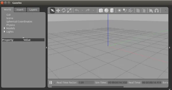
The Gazebo simulation software is used to simulate a robot on the 3D environment. By support of robust physics engine, high-quality graphics, open-source code, convenient customer and graphical interfaces, it allows to substitute the real robot by its simulation model, providing the calculation of the robot locomotion by the odometry and the sensor data. Therefore, the user can create 3D visualization, 6DOF and environment for the robot. The Gazebo software is developed in three steps to construct the 6DOF model, sensor models and 3D visualization for simulating the operations of the quad-rotor UAV. The components of the Gazebo software are shown in Fig. 2.7 [20].
Fig. 2.7 Components of the gazebo software
Model(Robot): Gazebo is defined a physical entity with dynamic, kinematic, and visual properties. The model of robot can be designed by three ways:
Code XML: Using the XML code to descript the components of robot. The example code is shown as:
<?xml version="1.0" ?>
<model name="robotFDCL">
<static>true</static>
<link name="link">
<collision name="collision">
<geometry>
<uri>file://media/robotFDCL.dae</uri>
<size>150 150 50</size>
<pos>0 0 0</pos>
</geometry>
</collision>
16
Draw tool in Gazebo: Using the block in the graphical user interface to make the model of robot as in Fig. 2.8.
Fig. 2.8 User interface in gazebo
Other software: Using some software to make 3D of the robot such as Solidwork and Catia. Then using the converter toolbox to make a model on the gazebo.
The example of the model robot is drawn from Solidwork and load into Gazebo which is shown in Fig. 2.9.
Fig. 2.9 Components of the gazebo software
17
Plugin(C code): A model may have one or more plugins, which affect the model's behavior. The plugins are written by the standard C++ classes. By using the libraries in Gazebo, the robot can be set the force and moment on 6DOF, visual the operation in 3D environment and measure state of itself through the sensor model which is built by the equation mathematical.
A example for IMU sensor model in gazebo is shown as:
math::Vector3 angular_vel_I = link_->GetRelativeAngularVel();
Eigen::Vector3d linear_acceleration_I(acceleration_I.x, acceleration_I.y, acceleration_I.z);
Eigen::Vector3d angular_velocity_I(angular_vel_I.x, angular_vel_I.y, angular_vel_I.z);
gazebo::msgs::Vector3d* linear_acceleration = new gazebo::msgs::Vector3d();
linear_acceleration->set_x(linear_acceleration_I[0]);
linear_acceleration->set_y(linear_acceleration_I[1]);
linear_acceleration->set_z(linear_acceleration_I[2]);
gazebo::msgs::Vector3d* angular_velocity = new gazebo::msgs::Vector3d();
angular_velocity->set_x(angular_velocity_I[0]);
angular_velocity->set_y(angular_velocity_I[1]);
angular_velocity->set_z(angular_velocity_I[2]);
World(Environment): Both the model and the plugin are put into the world file to simulate the operation of robot in the 3D environment. A displayed world file on gazebo is shown as in Fig. 2.10.
Fig. 2.10 A displayed world file in gazebo
2.5 Overview of hardware in the loop simulation
For any UAV development, The simulation is a necessary tool to reduce damages, experimental costs and save time in the development system. Recently, two simulations are used
18 to ensure safety in the design models, the control algorithms and the flight conditions, which is the software in the loop simulation and the hardware in the loop simulation. After have good results from two simulations, the UAV will be test with the realistic flight. The UAV development process is shown in Fig. 2.11.
Fig. 2.11 A UAV development process
Therein, the software-in-the-loop(SITL)-simulation [58] has been known as a valuable simulation process to verify the designed drone model and the flight control algorithms installed in the drone. Some researchers build the flight control algorithms based on Matlab/Simulink [58]
or PX4 source [10]. And the drone model model is built based on X-Plane [59], FlightGear [60], JMAVSim [61], or Gazebo [33]. The schema of SITL is shown in Fig. 2.12. Among them, PX4 source and Gazebo simulation have more advantages due to following reasons. First, PX4 [62] is an open source that includes many libraries to drive unmanned aerial and ground vehicles. In addition, PX4 can be uploaded to an open hardware Pixhawk [63] which is a very popular hardware for UAV applications. Second, Gazebo simulation is also an open source, and it can provide the dynamic model of UAV, sensor model and 3D visualization. In particular, this software contains the open dynamics engine(ODE), which can present a system model robot with high accuracy in real-time conditions [64].
19 Fig. 2.12 A scheme of SITL development
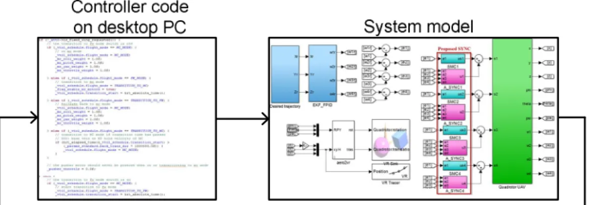
Hardware-in-the-loop-simulation (HILS) is well-known as an effective approach in the design of unmanned aerial vehicles (UAV) systems, enabling engineers to test the control algorithm on a hardware board with a UAV model on the software. HILS is an excellent way to test the UAVs system on real time platform, which combines a hardware device with simulation software. The hardware is used to installed flight control algorithms on the microchip while the simulation software provides the 6DOF model of UAV, sensors model, environment model and visualization to simulate the operation of robot. The schema of HILS is shown in Fig. 2.13.
Controller code
on hardware System model - Real time
Fig. 2.13 A schema of HILS development
20
Chapter 3. DEVELOPMENT OF HILS BASED ON PIXHAWK, GAZEBO AND CONTROL APPLICATION SOFTWARE
3.1 Introduction
In the UAV development process, the simulations need to be performed to reduce the risk of property damage resulting due to airframe crashes, system failure or controller malfunction. In order to prevent these problems from occurring, HILS is an excellent solution to test the UAVs system on a real-time platform, combining a hardware device with simulation software. The hardware is used to install control algorithms on the microchip, while a simulation software provides the nonlinear 6DOF model of UAVs, sensor models, environment models and visualization to simulate the UAV operation.
Some hardware, such as the AuRoRa board-STM32F3Discovery board [5], PhycoreMPC5200B-tiny embedded board [6], dSpace dsll03 board [7], Rabbit board [8] and FPGA microchip [9], were chosen to develop HILS for UAVs. Although these boards provided the real-time platform, these solutions are limited due to the complicated hardware components, which are inflexible, expensive and difficult to establish for various simulations.
In recent years, the Pixhawk hardware [10,11] has been widely used for UAV applications.
It provides high-end autopilot hardware with low costs and high availability. Furthermore, the control algorithms in the open-source code PX4 [12,13], which is autopilot firmware used to drive unmanned aerial and ground vehicles, can be installed on this hardware.
Pixhawk can be coupled with some simulation software to establish the HILS system. The jMAVSim [14] has been used to develop HILS for a multi-rotor UAV simulation. However, it has limitations with regard to complex model. Researchers have thus used other simulation
21 software such as MAV3DSim [15], GEFS [16], FlightGear [17] and Xplane [18]. Although they provide a simulation framework, such software still requires significant amount of effort when testing sensor-based high level control [19]. The cost of the commercial simulators needs to be considered in the development process.
To overcome these limitations, the Gazebo software [20] is popular in the robotics community and is completely open-source, so that the user can easily define 3D virtual worlds, sensor models and communication protocols. In particular, this software contains the open dynamics engine(ODE), which can present a system model robot with high accuracy in real-time conditions [21]. ODE can provide real-time dynamical simulations and the corresponding sensor readings for the UAVs [22,23].
In the traditional HILS setup, the algorithm installed on the hardware is connected to a 6DOF model on the simulation software via either a direct connection or using middleware software. In the first case, the parts of HILS are connected without any information regarding the state of line transfer within the HILS system [24,17,18]. Subsequently, the communication of HILS is conflicted, the time responses are slow and the signals between the hardware and simulation software are lost. Therefore, the HILS performance is totally deteriorated. In the second case, the middleware software robot operating system (ROS) can be used to overcome the limitations of the first case [22,24]. To achieve this, the ROS needs to integrate all parts of the HILS, including the hardware and software. Before transferring a signal to another part, the data need to be attached to an ROS message. Consequently, the HILS system becomes more complex, limiting its applicability.
Therefore, this chapter presents the development for a middleware software to secure communications in HILS system for testing the operation of a quad-rotor UAV. In our HILS, the Gazebo software is used to generate a nonlinear six-degrees-of-freedom (6DOF) model, sensor
22 model and 3D visualization for the quad-rotor UAV. Meanwhile, the flight control algorithm is designed and implemented on the Pixhawk hardware. New middleware software, referred to as the control application software (CAS), is proposed to ensure the connection and data transfer between Gazebo and Pixhawk using the multithread structure in Qt Creator. The CAS provides a graphical user interface (GUI), allowing the user to monitor the status of packet transfer, perform the flight control commands and the real-time tuning parameters for the quad-rotor UAV.
3.2 HILS design
The goal of HILS is to simulate the operation of a robot driven by the control algorithm in real-time conditions. By utilizing the mathematical model of the quad-rotor UAV presented in Chapter 2, a flight controller is designed and installed on the hardware board. The simulation software is required to configure the 6DOF model of the quad-rotor UAV, sensor models and environment models to provide the state of the UAV as well as a 3D visualization for HILS. In fact, the hardware board and the simulation software are developed and work in different platforms. Communication conflicts can exist between them due to data transfer without knowing information about the line data transfer. To solve this problem, a control communication unit is indispensable to ensure connection between the hardware board and the simulation software in HILS.
Therefore, this section explains the component schema of HILS, as shown in Fig. 3.1.
Herein, the Gazebo software is used to present the functions of the simulation software, while the Pixhawk hardware board is used to install flight control algorithms for the quad-rotor UAV.
Based on the 6DOF model of the quad-rotor UAV in Gazebo software, the data measured from sensor models are generated and sent to the Pixhawk hardware board. Similarly, the control signals from the controller in Pixhawk are sent to the Gazebo software. The CAS is developed to ensure the connection and data transfer between Gazebo and Pixhawk. Some extension
23 components in HILS, such as QGroundControl, other softwares and hardwares can connect to the CAS though a custom connection. This software uses the multithread method to avoid communication confliction, accelerate time response and reduce package loss during communication.
Fig. 3.1 Component schema of HILS
3.2.1 Design of simulation software
In this section, the Gazebo software is developed in three steps to construct the 6DOF model, sensor models and 3D visualization for simulating the operations of the quad-rotor UAV.
The components of the Gazebo software are shown in Fig. 2.7.
First, 3D CAD of the quad-rotor UAV was drawn in SolidWorks for the IRIS quad-rotor UAV from 3DR [72]. Herein, the user can define the parameters by material and color, and then the mass and moment of inertia of the UAV are calculated automatically. Based on the configuration of the UAV in SolidWorks, the SW2URDF toolbox in SolidWorks [45] was used to generate a URDF file which describes all elements, the kinematic and dynamic properties of a single UAV in isolation. It does not, however, specify the pose of the robot itself within a world.
In order to simulate this in the Gazebo, the pose of the UAV in the world needs to be added to the URDF file in order to create a new file called the SDF file, of which an example is shown in Fig. 3.2. The SDF file is loaded into the Gazebo to make a UAV model which has the 3D
24 visualization as in Fig. 3.3. This model can be applied the forces and moments in the 6DOF model by using the open dynamics engine library in the gazebo [20].
Fig. 3.2 Description of the SDF file
Fig. 3.3 Visualization of the quad-rotor UAV
Second, the sensor models and the motor control functions are added to the UAV model by using the C programming language of the plugin. Here, the sensor models measure the state of the UAV to provide feedback data to the flight controllers in Pixhawk. The motor control functions are used to set forces and moments for the 6DOF model of the UAV based on the angular velocity of each motor, which is given from the flight controllers. It is also used to visualize the flight motion of the UAV in Gazebo.
25 The sensor models of the inertial measurement unit (IMU) and the global positioning system (GPS) are selected for installation on the quad-rotor UAV. The IMU sensor data contains information on the orientation
, linear acceleration
a and angular velocity
va . The GPS sensor model provides the latitude
, longitude
and altitude
z . The Gazebo software is run to provide the IMU data
, ,a va
, the current position
x y z, ,
and the initial location
0, 0,z0
using the physics library. The current location
1, 1,z1
of the UAV can be calculated as [73]
1 0 0
1 0
0 0
1 0
arcsin cos c sin xsin c cos
ysin c arctan
cos c cos xsin c sin
z z z
(3.1)
where R is the radius of Earth, and
2 2
x y
c R
, x2y2.
By using the libraries (physics.hh), sensor (sensor.hh) in the gazebo, the IMU and GPS sensor model can be described in the example below code
//IMU
gazebo::msgs::Quaternion* orientation = new gazebo::msgs::Quaternion();
orientation->set_x(C_W_I.x);
orientation->set_y(C_W_I.y);
orientation->set_z(C_W_I.z);
orientation->set_w(C_W_I.w);
math::Vector3 angular_vel_I = link_->GetRelativeAngularVel();
Eigen::Vector3d linear_acceleration_I(acc_I.x, acc_I.y, acc_I.z);
Eigen::Vector3d angular_velocity_I(angular_vel_I.x, angular_vel_I.y, angular_vel_I.z);
26 addNoise(&linear_acceleration_I, &angular_velocity_I, dt);
//GPS
double x_rad = pos_W_I.x / earth_radius; double y_rad = -pos_W_I.y / earth_radius;
double c = sqrt(x_rad * x_rad + y_rad * y_rad);
double sin_c = sin(c);double cos_c = cos(c);
lat_rad = asin(cos_c * sin(lat_org) + (x_rad * sin_c * cos(lat_org)) / c);
lon_rad = (lon_org + atan2(y_rad * sin_c, c * cos(lat_org) * cos_c - x_rad * sin(lat_org) * sin_c));
Table 3.1 Parameters Gaussian noise for IMU and GPS sensors
Sensor Mean Standard Deviation
GPS 0 Lon/Lat/Alt=0.3mG
IMU 0 GyroX/Y/Z =0.67/0.78/0.12(0/s) ; AccX/Y/Z =0.04/0.06/0.07(m/s2)
Based on the sensor models of IMU and GPS, the sensor data are generated and the disturbances are added to them in two individual plugins. In this simulation, the Gaussian noise and white noise are placed in each sensor as shown in Table 3.1 [74,75]. To present and operate the real sensors in real-time conditions, the GPS and IMU signals are performed at the frequencies of 5Hz and 500Hz, respectively [24]. Because the sensors are achieved in different plugins, they are collected in a general interface plugin to publish to the controllers. Sensor plugins can send the information of sensors through the [transport::PublisherPtr] class with the Publish method to the general interface plugin which can receive the data through the [transport::SubscriberPtr] class with the Subscribe method. For example, the code in the listing below describes for the Publish and Subscribe methods in the plugins.
//IMU and GPS plugin code
transport::PublisherPtr imu_pub_; imu_pub_->Publish(imu_data_);
transport::PublisherPtr gps_pub_; gps_pub_->Publish(gps_data_);
27 //General interface plugin code
transport::SubscriberPtr imu_sub_; transport::SubscriberPtr gps_sub_;
imu_sub_ = node_handle_->Subscribe(imu_sub_topic_, &GazeboMavlinkInterface::ImuCallback, this);
gps_sub_ = node_handle_->Subscribe(gps_sub_topic_, &GazeboMavlinkInterface::GpsCallback, this);
Fig. 3.4 Flowchart describing the send/receive task between the plugins in Gazebo
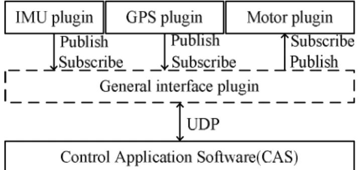
For any operation of the quad-rotor UAV, the motors need to be set with the angular velocity that was described in Chapter 2. The motor control functions are defined in a motor plugin via two methods. The first method is to receive the signal control from the controller and use the inverse function of Eq. (2.3) to calculate the angular velocity for each motor. Then, this angular velocity is used to visualize the rotation of the propeller. The second method is to calculate the forces and moments in Eqs. (2.1)(2.2) for each motor, and then set to the 6DOF model of the quad-rotor UAV. Similar to the IMU and GPS plugins, the motor plugin also needs to use the general interface plugin to send/receive the data with the applications outside the Gazebo. A flowchart describing the send/receive task between the plugins in Gazebo is shown in Fig. 3.4. Without loss of generality, the UDP protocol is selected for transferring and receiving the signals of Gazebo in the HILS system. All signals are encoded in the MAVLink message packet [11]. The IMU, GPS and motor messages are defined in the list below.
#pragma once // MESSAGE IMU (HIL_SENSOR)
#define MAVLINK_MSG_ID_HIL_SENSOR 107
28 MAVPACKED(typedef struct __mavlink_hil_sensor_t { uint64_t time_usec;
float xacc,yacc,zacc,xgyro,ygyro,zgyro, xmag,ymag,zmag; }) mavlink_hil_sensor_t;
#pragma once // MESSAGE GPS (HIL_GPS)
#define MAVLINK_MSG_ID_HIL_GPS 113
MAVPACKED(typedef struct __mavlink_hil_gps_t { uint64_t time_usec;
int32_t lat,lon,alt; }) mavlink_hil_gps_t;
#pragma once // MESSAGE MOTOR (HIL_CONTROLS)
#define MAVLINK_MSG_ID_HIL_CONTROLS 91
MAVPACKED(typedef struct __mavlink_hil_controls_t { uint64_t time_usec;
float roll_aileron, pitch_elevator, yaw_rudder, thottle; //U2//U3//U4//U1 }) mavlink_hil_controls_t;
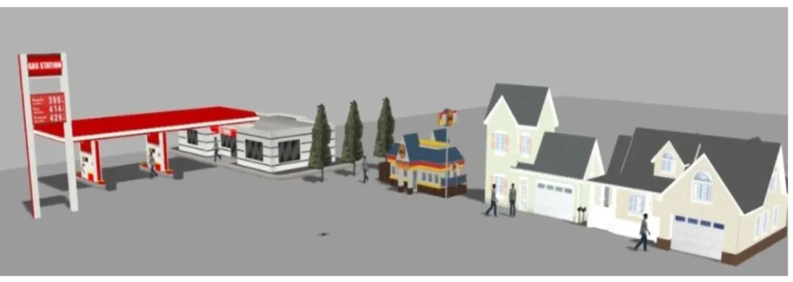
Third, the quad-rotor UAV model and the plugins are put into a world file to setup the working environment for the simulations. In the world file, we can design other models, including trees, wind, houses and cars. Real-time conditions are also configured in this file based on the ODE. An example display of the world file in the Gazebo software is shown in Fig. 3.5.
Fig. 3.5 Visualization of the world file in the Gazebo software
29 3.2.2 Development of Pixhawk
The Pixhawk hardware board is used to install the flight control algorithm for the quad- rotor UAV, providing the real-time environment based on the NuttX real-time operation system [21]. A tracking control algorithm is designed as shown in Fig. 3.6.
r r, r
, ,
r
, ,
r r r
X Y Z
, , X Y Z
X, Y
e e
eZ
2, 3
U U U4
U1
1
2
3
4
Fig. 3.6 Block diagram of a tracking controller for the quad-rotor UAV
Here, the quad-rotor UAV is driven to follow the trajectory described by the position
X Y Zr, r, r
and yaw
r . The altitude, position and attitude controller are designed to generate the force and moment (U1, U2, U3 and U4) as presented in Chapter 2. The altitude controller refers to the error distance(ez) as the input and results in the U1 signal. Meanwhile, the input of the position controller uses the error position (ex, ey) and its output provides roll
r and pitch
r which are combined with the yaw reference to make desired inputs to the attitude controller.The output signals of this controller are put into the inverse function of Eq. (2.3) to obtain angular velocities (w1, w2, w3, and w4) for the motors in the quad-rotor UAV.
To implement the control algorithm, the PID controller [13] is selected for the altitude, position and attitude controller. The IMU and GPS sensor models in Gazebo are used to generate feedback signals
, , ; X Y Z, ,
. Based on the libraries of the open-source PX4, the controllers are written in the mc_pos_control and mc_att_control files using C programming language, and these codes are compiled in firmware that is loaded to the microchip of the30 Pixhawk hardware. The process from PX4 source to uploading the firmware to Pixhawk is shown in Fig. 3.7.
Fig. 3.7 Compiling and uploading the firmware to Pixhawk
In our research, the softwares that provide the editor code, compiler code and upload firmware, are shown in Table 3.2.
Table 3.2 List softwares use in the proposed HILS
Name Version Description
PX4 source v1.5.0 Open source for developing controllers Qt creator v5.7.0 Editor code, installed on Ubuntu OS Ground control station (GCS) v3.0.1 Upload firmware, named QGroundControl
3.2.3 Design of Control application software
The Gazebo software is designed to simulate the tasks of the quad-rotor UAV under the flight controllers which are installed in the Pixhawk hardware. The CAS is developed to ensure data communication between the Gazebo and the Pixhawk. It is designed with custom connections and service that is required from the hardwares and softwares in the HILS system.
The detailed structure of the CAS proposed in this paper is presented in Fig. 3.8.
31 Fig. 3.8 Structure of the CAS
Here, the CAS includes a connection module, thread module, command flight control module and monitoring module. The connection module is used to define the interface between the CAS and other applications on the hardware(software) through the serial, UDP and TCP connections. Therefore, the middleware software CAS does not need to be integrated with the other components of the HILS like the ROS. To up speed for the communication in HILS, the thread module provides the threads corresponding to each connection. The threads can be activated in parallel at the same time to control the process of receiving and sending data with the applications. To avoid conflicts on each thread and on all systems, the synchronization method is used to synchronize data, and the threads often check the line status before transferring data to the applications. Furthermore, the CAS defines the flag forward status to limit the number of packets to each thread because the applications need only some of the information that is transferred in the HILS system. The monitoring and the command flight control modules allow the users either to track the state of the HILS s