DOI http://dx.doi.org/10.11004/kosacs.2012.3.4.010
신뢰성 해석에 의한 내폭 CFRP-steel 복합구조의 최적화 설계
김정중
1· 노혁천
2세종대학교 건설환경공학과 연구교수1, 세종대학교 건설환경공학과 부교수2
Design Optimization of Blast Resistant CFRP-steel Composite Structure Based on Reliability Analysis
Kim, Jung Joong
1· Noh, Hyuk-Chun
21Research Professor. Department of Civil and Environmental Engineering, Sejong University, Seoul, Korea
2Associate Professor, Department of Civil and Environmental Engineering, Sejong University, Seoul, Korea
Abstract: This study presents the effectiveness of a composite structure at improving blast resistance. The proposed composite structure consists of carbon fiber reinforced polymer (CFRP) and steel layers. While CFRP layer is used for blast energy reflection due to its high strength, steel layer is used for blast energy absorption due to its high ductility.
A dynamic model is used to simulate the elastoplastic behavior of the proposed composite structure subject to blast load. Considering the magnitude variations of a blast event, the probability of failure of each layer is evaluated using reliability analysis. By assigning design probability of failure of each layer in the composite structure, the thickness of layers is optimized. A case study for the design of CFRP-steel composite structure subjected to an uncertain blast event is also presented.
Key Words: CFRP, Blast resistance, Composite structure, Reliability analysis, Optimization
주요어: CFRP, 내폭, 복합구조, 신뢰성해석, 최적화
Corresponding author: Noh, Hyuk-Chun
Department of Civil and Environmental Engineering, Sejong University, 98 Gunja-dong, Gwangjin-gu, Seoul 143-747, Korea.
Tel: +82-2-3408-3292, Fax: +82-2-3408-4332, E-mail: [email protected]
투고일: 2012년 11월 26일 / 수정일: 2012년 12월 10일 / 게재확정일: 2012년 12월 21일
1. Introduction
Military vehicles are usually protected by armor from a blast or impact loading. While steel is the most commonly used material for armor, other materials are also used for enhancing armor such as uranium to transmit low loads by its high density.
There are also demands for lighter materials for armor to increase vehicle mobility. Carbon fiber reinforced polymer (CFRP) is considered as efficient substitute for steel due to its various advantages such as lower weight, higher strength and corrosion resistance (Emmons et al. 1998, Rizkalla et al. 2003).
When an explosion event occurs, a significantly large amount of energy is released over a short time period. Most of the energy released is contained in the blast wave. Specific impulses as well as the value of over pressure above ambient pressure are used to describe and characterize the blast wave with time.
Because the blast wave moves farther from the
detonation source, the over pressure decays (Smith and
Hetherington 1994). The material behavior according to
strain rate loading must also be considered for realistic
modeling (Xia et al. 2007). Fluid structure interaction
has been shown a significant effect on the pressure
distribution and transfer (Ngo et al. 2007). As
deterministic blast simulations cannot provide a robust design given the significant sensitivity of blast simulation to many uncertain parameters that govern any blast (Borenstein and Benaroya 2009), a reliability-based approach was proposed for the design of blast-resistant composites (Kim et al. 2011). While the importance of the above issues in rational simulation of blast events was acknowledged, it is emphasized here that uncertainty consideration in blast events is necessary for blast resistant design.
In this study, a simplified dynamic model is developed to simulate dynamic behavior of a composite structure under blast air pressure. For an uncertain blast event, the probability of failure of each layer is evaluated using reliability analysis. By assigning a high probability of failure to steel layer and a relatively low probability of failure to CFRP layer, the thickness of the composite layers is optimized. A case study for the design of CFRP-steel composite structure subjected to an uncertain blast event is presented and the results are discussed.
2. Methods
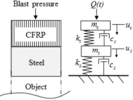
1. CFRP-steel composite structure
For the modelling of CFRP-steel composite structure subject to air pressures due to blast, elastoplastic dynamic responses of mass, damper and spring system (Biggs 1982) are used. CFRP layer, which is subjected to the blast pressure, is considered as reflecting layer and steel layer is considered as absorbing layer.
Therefore, constitutive response of CFRP layer is modeled as elastic and that of steel layer is modeled as idealized elastoplastic as shown in Fig. 1.
) , ( s s
s u u
f &
us
fsy
ks
ks
fsy
−
Fig. 1 Idealized elastoplastic model of steel in a composite structure
The composite structure, consisting of CFRP and steel layers as shown in Fig. 2, is modeled as two
lumped mass system. The equation of motion of this system is then formulated as
(1)
where and u are acceleration, velocity and displacement of two layers respectively as shown in Fig. 2 and m and c are mass and damping constant per unit area respectively.
is resisting stress according to the applied strain rate considering elastoplastic constitutive of steel in Fig. 1. k is the stiffness per unit area of layers computed as the modulus of elasticity over the layer thickness. Q is the applied blast pressure with respect to time to CFRP layer. Subscript “s” and “c” represent the corresponding properties of steel layer and CFRP layer respectively.
Fig. 2 Lumped mass, damper and spring modeling of CFRP-steel composite structure
For our interest, the maximum stress f
CFRPin CFRP and the maximum strain
in steel during the response time are computed as
max
(2)
max
(3)
where, h
sis the thickness of steel layer. It is noticeable that the stress transferred to object as shown in Fig. 2 will be constraint to the yield strength of steel, f
sy.
2. Reliability analysis
To incorporate uncertainties in applied load to a
structure and mechanical material properties of the structure to structural design, reliability analysis has been used (Melchers 1999, Nowak and Collins 2000).
Limit states of CFRP and steel layers are defined to establish undesirable conditions (failure) for the layers.
For the limit state of CFRP, the maximum stress f
CFRPin CFRP during dynamic response to a blast wave should be less than the maximum elastic stress of CFRP, f
maxto reflect all energy applied to the layer.
Therefore, the limit state G
cof CFRP layer is defined as
m ax
(4)
Considering that the use of steel is for absorbing the applied blast energy in the layer as strain energy, this layer needs to yield. If the strain energy capacity of steel is incapable of absorbing the strain energy by blast, the layer response is undesirable. Therefore, the limit state G
sof steel layer is defined as
(5)
where,
is failure strain of steel. The failure of steel layer will take place when G
sis less than or equal to zero. The integration of joint probability density functions (PDF) of
and
for the violation region of limit state
≤ will give the probability of failure of steel layer. The probability of failure of CFRP layer is also computed similarly. To simplify the design problem, the probability of failure is converted to reliability index using the relationship as:
(6)
where is the inverse of the standard normal cumulative density function (CDF).
3. Design optimization using reliability index
The optimization process is formulated to identify the optimal thickness of each layer to have a certain level of reliability of the composite structure subjected to an uncertain blast event. The optimal thickness combination of the layers gives the desired reliability index, denoted
and
for CFRP and steel layers
respectively. The optimization problem can be posed as:
min
m in≤ ≤
m ax∀
(7)
where h
minand h
maxare the lower and upper bounds of each layer thickness respectively. The thickness ranges for CFRP and steel were selected from 2 mm to 20 mm and from 50 mm to 150 mm respectively in this study.
3. Case Study
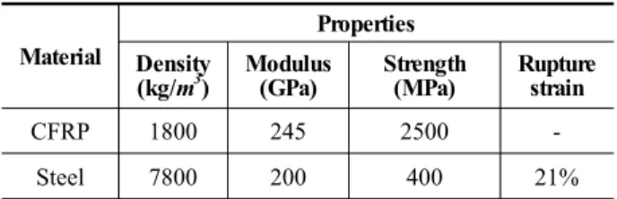
Mechanical properties of CFRP and steel for a case study are presented in Table 1.
Table 1. Mechanical properties of CFRP and steel for the proposed composite structure
Material
Properties Density
(kg/m3) Modulus
(GPa) Strength
(MPa) Rupture strain
CFRP 1800 245 2500 -
Steel 7800 200 400 21%
To simulate blast pressure, Friedlander decay function (Smith and Heatherington 1994, Park et al.
2006, Kim et al. 2011) is used here such as
exp
(8)
where Q
mis the maximum magnitude of the positive pressure due to blast. t
dis the time duration of the positive pressure and is the shape factor for the blast model.
-100 0 100 200 300 400 500
0 5 10 15
Blast air pressure (MPa)
Time (ms)
Fig. 3 Friedlander blast air pressure wave (Qm = 500 MPa and td = 0.018 sec)
The selected blast produced an incident pressure of 500 MPa on the outer composite surface. Selection of the blast incident was performed with the intention to produce significantly high stress in the composite structure. In this model t
dand are selected as 0.0018 sec and 1.0 respectively. The blast model is formulated in Fig. 3. Dynamic responses of the composite plate due to the blast load were analyzed according to the layer thicknesses of CFRP and steel varying from 2 mm to 20 mm and from 50 mm to 150 mm respectively. The damping coefficients for both layers are assumed as viscous damping
(Chopra 2001). Here, the damping ratio of 1% is used for both layers. It is also assumed that bonding between two layers holds perfectly during the blast loading.
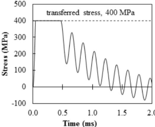
The transferred stress to the protection object is formulated in Fig. 4 with respect to the combinations of CFRP and steel thicknesses. The transferred stress was determined from the dynamic response of stress in steel of the composite structure. For example, the dynamic response of stress in steel of the composite structure consisting of 10 mm CFRP and 150 mm steel is presented in Fig. 5 As expected, the yield strength 400 MPa of steel governed the transferred stress for all the selected thickness ranges.
Fig. 4 Transferred stress to the protection object, which is equivalent to the maximum stress in steel.
Marked point is determined from stress evolution in steel in Fig. 5 for example
The maximum stress in CFRP with respect to the combinations of CFRP and steel thicknesses are computed in Fig. 6. The dynamic response of stress in CFRP of the composite structure consisting of 10 mm CFRP and 150 mm steel is presented in Fig. 7 for
example. As shown in Fig. 6, the maximum stress in CFRP decreases when CFRP thickness increases and steel thickness decreases.
Fig. 5 Stress evolution in steel of the composite structure consisting of 10 mm thick CFRP and 150 mm thick steel due to blast air pressure wave in Fig.
2
The maximum strain in steel with respect to the combinations of CFRP and steel thicknesses are computed in Fig. 8. The dynamic response of strain in steel of the composite structure consisting of 10 mm CFRP and 150 mm steel is also presented in Fig. 9.
In Fig. 8, the maximum strain in steel decreases when steel thickness increases. However, the maximum strain in steel is not sensitive for the change of CFRP thickness. The maximum strain of steel is computed under its rupture strain 21% for all selected analysis region as shown in Fig. 8.
Fig. 6 The maximum stress in CFRP. Marked point is determined from stress evolution in CFRP in Fig. 7 for example
Fig. 7 Stress evolution in CFRP of the composite structure consisting of 10mm CFRP and 150mm steel due to blast air pressure wave in Fig. 2
Fig. 8 The maximum strain in steel. Marked point is determined from strain evolution in CFRP in Fig.
9 for example
Fig. 9 Strain evolution in steel of the composite structure consisting of 10 mm CFRP and 150 mm steel due to blast air pressure wave in Fig. 2
Considering uncertain blast event, the magnitude of blast pressure Q
mwas assumed normally distributed to have a coefficient of variation (COV) of 30% (Altunc et al. 2011). In the meantime, the rupture strengths of CFRP and the rupture strain of steel were assumed to be normally distributed with COVs of 10% for both
properties.
4. Results and Discussion
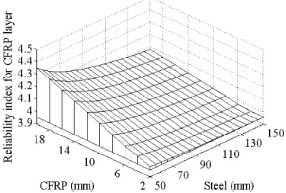
By assigning these uncertainties to the limit state functions in Eqs. (2) and (3), probability of failure for CFRP and steel with respect to layer thicknesses are computed and formulated as reliability index in Fig.
10 and Fig. 11 respectively.
Fig. 10 Reliability index of CFRP
Reliability index for both CFRP and steel increases with increase of layer thicknesses. To determine optimum thicknesses of CFRP and steel for an uncertain blast event using Eq. (7), the following design reliability index for each material is considered:
for CFRP (corresponding to probability of failure of 0.003%) and
for steel (probability of failure of 2.275%). Reliability index for conventional strength design is assigned to CFRP while a relatively low reliability index is assigned to steel by considering steel as a consumable and replaceable.
Fig. 11 Reliability index of steel
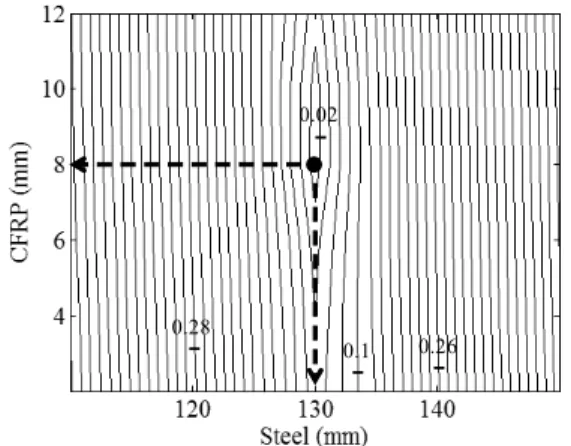
By formulating objective function in Eq. (7) as shown in Fig. 12, the optimal combination of 8 mm thick CFRP and 130 mm thick steel for the composite structure can be obtained. The corresponding contour plot is presented in Fig. 13.
Fig. 12 Objective function surface.
If there exist more than two optimal solutions due to significant non-linearity of the beta surfaces, the optimal solution can be determined by minimizing the use of materials. In this case, a cost function can be utilized as a secondary objective. The cost of the composite plate might be a weighted function of CFRP and steel thicknesses.
0.02
0.1 0.26 0.28
Fig. 13 Contour plot of the objective surface in Fig. 12
The optimal composite structure to resist uncertain blast event having a mean maximum pressure 500 MPa with 30% COV is then determined to have a total thickness of 138 mm (8 mm CFRP and 130 mm steel). The dynamic responses for this composite structure can be computed as the residual strain of steel approaches 4.1%, while CFRP layer stress reaches 969 MPa right after blast. It is important to
note that a realistic blast event will not generate uniform pressure on the surface of the composite plate and materials yield typically happens locally.
Therefore, while the above method provides a simplified approach for design of the composite structure, detailed analysis of the composite structure is necessary to examine the effect of the blast event using finite element (FE) analysis.
5. Conclusions
In this study, a simplified reliability-based design method of blast-resistant composite structure is presented along with a case study. The composite structure consists of CFRP and steel to reflect and absorb the blast energy. Different levels of target reliability indices are assigned to each material to consider the different purposes of each material. A design example of a CFRP-steel composite structure subjected to an uncertain blast event is presented. The optimized CFRP-steel composite structure proved the ability of the structure to resist blast events. As the analysis used in this study neglects strain rate-dependent material properties, the proposed design method might be considered as a conservative design methodology of composite structure for enhanced blast resistance.
Acknowledgment
This work was supported by the Human Resources Development program (No. 20124030200050) of the Korea Institute of Energy Technology Evaluation and Planning (KETEP) grant funded by the Korea government Ministry of Knowledge Economy research.
References
Altunc, A. B., Kim, J. J., Al-Haik, M., Reda Taha, M.
M. (2011). “Reliability-Based Design of Blast - Resistant Composite Laminates Incorporating Carbon Nanotubes”, Compos. Struct., 93, pp.
2042-2048.
Biggs, J. M. (1982). Introduction to Structural Dynamics, McGraw-Hill, Inc, New York, NY.
Borenstein, E., Benaroya, H. (2009). “Sensitivity Analysis of Blast Loading Parameters and Their Trends as Uncertainty Increases”, J. of Sound and Vib., 32,
pp. 762–785.
Chopra, A. K. (2001). Dynamics of Structures, Theory and Applications to Earthquake Engineering, 2nd Ed.,Prentice-Hall, Upper Saddle River, NJ.
Emmons, P. H., Vaysburd A. M., Thomas, J. (1998).
“Strengthening Concrete Structure, part II.”
Concrete International, 20, pp. 56-60.
Kim, H. J., Yi, N. H., Kim, B. S., Nam, J. W., Ha, J.
H, Kim, J. J. (2011). “Debonding Failure Analysis of FRP-Retrofitted Concrete Panel under Blast Loading”, Struct. Eng. and Mech., 38, pp.
479-5011.
Melchers, R. E. (1999). Structural Reliability Analysis and Prediction, Second Edition, John Wiley & Sons, New York, NY.
Ngo, T., Mendis, P., Gupta, A., Ramsay, J. (2007).
“Blast Loading and Blast Effects on Structures – An Overview”, Electronic J. of Struct. Eng., 7, pp.
76–91.
Nowak, A. S., Collins, K., (2000). Reliability of Structures, McGraw-Hill, New York, NY.
Park, H., Lee, K., Lee, S. W., Kim, K. (2006). “Dynamic Analysis of Nonlinear Composite Structures under Pressure Wave Loading”, J. of Compos. Mater., 40, pp.1361-1383.
Rizkalla, S., Hassan, T., Hassan, N. (2003). “Design Recommendations for the Use of FRP for Reinforcement and strengthening of concrete structures.” Progress in Structural Engineering and Materials, 5, pp.16-28.
Sheyka, M. P., Kim, J. J., Altunc, A. B., Reda Taha, M.
M. (2011). A Reliability-Based Energy Approach for Design Optimization of Blast Resistant Composites, Proceedings of ASME 2011 International Mechanical Engineering Congress and Exposition, Nov. 17-20, Denver, CO.
Xia, Y., Wang, Y., Zhou, Y., Jeelani, S. (2007). “Effect of Strain Rate on Tensile Behavior of Carbon Fiber Reinforced Aluminum Laminates.” Mater.
Lett., 61, pp.213–215.