1. INTRODUCTION
The Gravity Recover y And Climate E xperiment (GRACE) satellite was developed as part of the combined project carried out by National Aeronautics and Space Administration of the US and Deutsches Zentrum fur Luft und Raumfahrt of Germany. Major duties of the GRACE satellite include the precise mapping process for the gravity field of the Earth, and the measuring process for the related time changes (Tapley et al. 2004). For such a purpose, two units of the GRACE satellite have been arranged and put on the same orbit with the distance of about 200 km both them.
For the precise calculation of the satellite orbit and the measurement of the gravity field of the Earth, the GRACE satellites are equipped with the BlackJack GPS Receiver, the Super STAR Accelerometer, the Star Sensor (Star Tracker), the K-band Ranging System, and the Satellite Laser Ranging Reflector. The BlackJack GPS receiver installed on the GRACE satellites can be used up to 16 channels. The twelve
Precise Orbit Determination of GRACE-A Satellite with Kinematic GPS PPP
Byung-Kyu Choi
1†, Kyoung-Min Roh
1, Sung-Moon Yoo
1, Jung-Hyun Jo
2, Sang-Jeong Lee
31
Astronomy and Space Technology R&D Division, Korea Astronomy and Space Science Institute, Daejeon 305-348, Korea
2
Astronomy and Space Program Division, Korea Astronomy and Space Science Institute, Daejeon 305-348, Korea
3
Department of Electronics Engineering, Chungnam National University, Daejeon 305-764, Korea
ABSTRACT
Precise Point Positioning (PPP) has been widely used in navigation and orbit determination applications as we can obtain precise Global Positioning System (GPS) satellite orbit and clock products. Kinematic PPP, which is based on the GPS measurements only from the spaceborne GPS receiver, has some advantages for a simple precise orbit determination (POD).
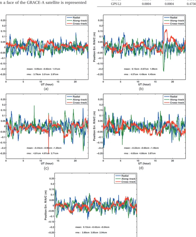
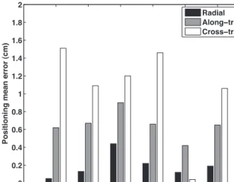
In this study, we developed kinematic PPP technique to estimate the orbits of GRACE-A satellite. The comparison of the mean position between the JPL’s orbit product and our results showed the orbit differences 0.18 cm, 0.54 cm, and 0.98 cm in the Radial, in Along-track, and Cross-track direction respectively. In addition, we obtained the root mean square (rms) values of 4.06 cm, 3.90 cm, and 3.23 cm in the satellite coordinate components relative to the known coordinates.
Keywords: GRACE-A, kinematic, PPP, POD
channels are used for the measurement of the precise orbit, while the remaining four are used for the measurement of the occultation for the GPS satellite. The GPS measurements of GRACE satellites are obtained with 10-second intervals.
The orbit estimation of the low earth orbit (LEO) satellite largely is classified into kinematic, dynamic, and reduced- dynamic methods. They can be applied in the orbit determination based on different types of observation data and data-processing strategies. The ‘dynamic’ method is the most general method of the orbit determination.
All factors of the physical acceleration which affects the satellite and every related model parameters should be considered. Since the ‘kinematic’ method requires only the GPS measurements without using the orbital equation, it can be applied to the orbit determination in a simple way (Montenbruck 2003). However, this could reveal different performances for the orbit of the satellite based on the level of accuracy given by the measurement model and the quality of the observation data. The ‘reduced-dynamic’
method applies the geometrical correction to the orbit of the satellite, which is obtained by using the typical ‘dynamic’
method, by using the GPS measurement. The well-known GIPSY/OASIS II developed by Jet Propulsion Laboratory (JPL) of the US can be regarded as the most representative Received Aug 30, 2012 Revised Oct 20, 2012 Accepted Oct 21, 2012
†
Corresponding Author E-mail: [email protected]
Tel: +82-42-865-3237 Fax: +82-42-862-5610
software which is used to the orbit determination of the satellite with the ‘reduced-dynamic’ method (Webb &
Zumberge 1995).
In recent studies, Li et al. (2010) obtained the root mean squares (RMS) value within the error of 3-5 cm along the radial direction of the GRACE-B satellite with the Kinematic PPP for seven days. Choi & Lee (2011) also precisely determined the GRACE-A orbit by using the Bernese 5.0 software which is developed by Bern university in Swiss.
They presented that the orbit error in the solution is typically within 3-5 cm RMS.
In this study, the dynamic models were not applied for the orbit determination of GRACE-A satellite. We used the
‘kinematic’ method with the dual-frequency GPS data.
For the ‘kinematic’ POD, the precise point positioning (PPP) technique was also applied (Kouba & Héroux 2001, Bisnath et al. 2002, Geng et al. 2010). In addition, this study described the strategies for the pre-processing of the GPS data, the composition of the measurement equation, and the orbit determination. In order to verify the results obtained with our software, the results were compared to the ‘reduced-dynamic’ method of JPL.
2. MEASUREMENT EQUATION AND ORBIT DETERMINATION STRATEGIES
In general, the onboard GPS receivers at the LEO satellite receive dual-frequency GPS code and carrier phase observations. The measurement equation of carrier phase for the LEO satellite is as the following Eq. (1) (Kouba &
Héroux 2001).
( )
IF
ρ c t δ δ T δ pco λ n ε
Φ = + − + + ⋅ + (1) where ρ is the geometric distance between the GPS receiver and the satellite, δt and δT are the clock errors related to the satellite and the receiver respectively, c is the speed of light, δpco is the antenna phase centers and the related changes of the satellite and the receiver, λ is the wavelength, and n is the linear combined float ambiguities, є is the system noise including multi-path. Ionosphere error can effectively be removed more than 99% by forming a linear combination of dual-frequency observables. In case of the low-orbit satellite, the tropospheric delay is not considered (Hofmann-Wellenhof et al. 2008).
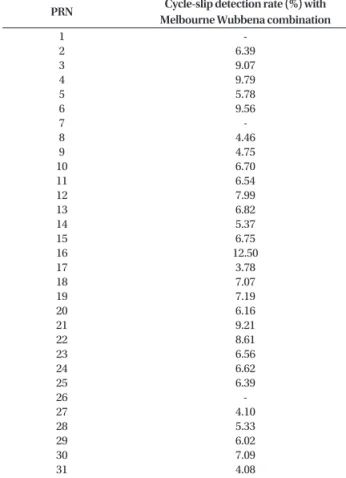
The pre-processing process step of the GPS data contains the outlier detection, the cycle-slip detection and the calculation of initial ambiguities. The main purpose of the pre-processing step is to obtain the reliable GPS
measurements ahead for the orbit determination. Table 1 shows the cycle-slip occurrence rate given by the Melbourne Wubbena combination. When any value exceeds the marginal value (2 sigma) which is established in advance through the pre-processing process, the state is regarded as the cycle-slip. As the GRACE-A satellite moves very fast (7 km/sec) and is exposed on severe environment in the space, the cycle-slip occurrence rate was revealed to be about 6.9%.
This means that 6.9% of the total amount of the GPS data is not used for the orbit determination of the satellite.
Table 1. Cycle-slip occurrence rate with the Melbourne Wubbena combination of all GPS satellites with in the data pre-processing (%).
PRN Cycle-slip detection rate (%) with Melbourne Wubbena combination
1
2 3 4 5 6 7 8 9 10 11 12 13 14 15 16 17 18 19 20 21 22 23 24 25 26 27 28 29 30 31 32
- 6.39 9.07 9.79 5.78 9.56 - 4.46 4.75 6.70 6.54 7.99 6.82 5.37 6.75 12.50 3.78 7.07 7.19 6.16 9.21 8.61 6.56 6.62 6.39 - 4.10 5.33 6.02 7.09 4.08 9.58
Total 6.91
Table 2. Orbit determination strategy for the LEO satellite with the kinematic PPP.
Item Description
LEO satellite Estimation period Processing intervals Position mode Estimated parameters Cutoff angle Tropospheric model Receiver antenna model Phase wind-up Processing filter Estimation Strategy
GRACE-A
2008.10.09. - 2008.10.13.
60 seconds Kinematic
Position, Receiver clock & clock drift 0 degrees
None
GRACE-A antenna offset (Level 1B) On
EKF
PPP
Table 2 gives information about the orbit estimation of the GRACE-A satellite. The Extended Kalman Filter (EKF) was applied in our software for the orbit estimation of the GRACE-A satellite. The parameters estimated in a process are consisted of the receiver position, the clock error of the receiver, and the drift of the clock error.
The phase center offset value of the GPS antenna mounted on a face of the GRACE-A satellite is represented
in Table 3. As the Earth observing satellites including the GRACE-A satellite maintain the local vertical local horizontal coordinate in the normal operation, we assumed Table 3. Phase center offset of the GPS Receiver onboard on the GRACE-A Satellite (Jäggi 2006).
GRACE-A antenna offset East (m) North (m) Up (m)
GPS L1
GPS L2
0.0004 0.0004
0.0004 0.0004
0.45142 0.47565
0 5 10 15 20
−0.25
−0.2
−0.15
−0.1
−0.05 0 0.05 0.1 0.15 0.2 0.25
UT (hour)
Position Err. R/A/C (m)
mean: 0.05cm −0.62cm 1.51cm rms : 3.79cm 3.51cm 2.97cm
Radial Along−track Cross−track
0 5 10 15 20
−0.25
−0.2
−0.15
−0.1
−0.05 0 0.05 0.1 0.15 0.2 0.25
UT (hour)
Position Err. R/A/C (m)
mean: 0.13cm −0.67cm 1.09cm rms : 4.57cm 4.49cm 4.45cm
Radial Along−track Cross−track
0 5 10 15 20
−0.25
−0.2
−0.15
−0.1
−0.05 0 0.05 0.1 0.15 0.2 0.25
UT (hour)
Position Err. R/A/C (m)
mean: −0.44cm −0.90cm −1.20cm rms : 4.81cm 4.97cm 3.71cm
Radial Along−track Cross−track
0 5 10 15 20
−0.25
−0.2
−0.15
−0.1
−0.05 0 0.05 0.1 0.15 0.2 0.25
UT (hour)
Position Err. R/A/C (m)
mean: −0.22cm −0.66cm −1.46cm rms : 4.63cm 4.66cm 3.87cm
Radial Along−track Cross−track
0 5 10 15 20
−0.25
−0.2
−0.15
−0.1
−0.05 0 0.05 0.1 0.15 0.2 0.25
UT (hour)
Position Err. R/A/C (m)
mean: 0.12cm −0.42cm −0.04cm rms : 3.80cm 3.85cm 2.94cm
Radial Along−track Cross−track