Development of Dual Mode (Autonomous and Remote Control) Unmanned Surface Vehicle
Hyo-Il Kim1․Seung-Hwan Jun†⋅Serng-Bae Moon2
(Received July 31, 2009; Revised November 19, 2009; Accepted January 11, 2010)
Abstract:These days, a study on 'Unmanned Surface Vehicle (USV)' has made very active progress in many countries. Even if it is being expected that there will be a great demand of USV for wide field, such as military operation, private sector, and etc., the study of USV in Korea is still at an early stage. For this reason, we have made a very small USV which is composed of dual mode (autonomous and remote control). The TCP/IP communication is applied to the USV.
Key words:USV, dual mode, remote control, autonomous navigation, TCP/IP
†Corresponding Author (Division of Navigation Science, National Korea Maritime University), E-mail: [email protected], Tel: 051-410-4245)
1 Graduate School of Navigation System Engineering, National Korea Maritime University 2 Division of Navigation System Engineering, National Korea Maritime University
1. Introduction
The study about USV has made in many other countries such as the US, Israel, Japan, German, Canada, and etc [1]. The reason is that the world market about the USV will be expected to be getting expand very much. U.S.-based market research firm Visiongain predicted that the USV market in the US will be approximately 160 million dollars in 2009 [2]. Other research institutions forecasted that the Navy, Coast Guard, and NOAA will acquire about 300 USVs through 2011, including the Remote Minehunting System. This represents approximately 1.8 billion dollars in expenditures for development and procurement beginning in 2004 [3].
In the meanwhile, some institutes in
Korea have been conducting the research and development of USV. Shim et al designed an neural PID controller of USV with two fixed thrusters in order to control AUV(Autonomous underwater Vehicle) fleet and verified effectiveness of the controller [4]. Son et al proposed an autonomous navigation algorithm using only the DGPS information for close-range observation of USV [5]. Kim and Jun developed an autonomous navigation algorithm of USV and verified its effectiveness through the sea trial test [6].
Overseas cases about USV's research were as follows. E.T. Steimle and M.L.
Hall made the catamaran type of USV with some equipments and carried out some tests to see the various applications of the USV as environmental monitoring
and assessment tools [7]. The USV was installed wireless modem of IEEE 802.11g protocol and was controlled by both autonomous and remote control methods.
T.W. Vaneck designed a fuzzy controller for autonomous navigation of USV [8].
According to the above circumstances, the USV will be expected to be widely used both military operation and private sector in the near future. Therefore, we have made a dual mode USV which is capable of autonomous and remote control through TCP/IP communication. The USV was applied to self-monitoring system for more stable operation and carried out some tests based on the system.
2. USV System
The configuration of the USV system is composed of the USV and Control Station.
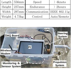
The system is available for two-way communication, because it is connected with wireless modem through IEEE 802.11g protocol between the USV and Control Station. Hence, Control Station is able to set up waypoints and navigation mode of the USV. On the contrary, the USV transmits the data acquired from the GPS and sensor systems to the Control Station. As a result, the operator is able to monitor the USV. Figure 1 represents the configuration of USV system.
Figure 1: Configuration of USV System
Length 556mm Speed > 4knots
Height 237mm Endurance > 2hours Width 297mm Communication IEEE 802.11g
Weight 4.73kg Control Auto/Remote
Table 1: Specifications of USV
Figure 2: Dual Mode USV
2.1 Specification and Configuration
For this study, we have made a barge type of USV which has three stabilization plates at the bottom. They are a kind of bilge keel to improve the stability and reduce rolling and yawing. Table 1 shows some specifications of the USV. Figure 2 is an appearance of the USV.
2.1.1 Propulsion System
The propulsion system of the USV is composed of the battery(DC 11.1V Li-Po cell), Electronic Speed Controller(ESC), and the engine system which consists of 3-phase AC motor(max. power is 420W), shaft, and propeller(Φ 60mm, pitch 83.9mm). The ESC converts 11.1V DC into 3-phase AC. When the AC motor is supplied with current, it generates the torque which is transferred to the propeller through the shaft.
2.1.2 Steering and Cooling System of USV
The steering system of the USV is
composed of a DC servo-motor and a rudder; both of them are linked with a connecting rod. Meanwhile, the ESC and AC motor are applied air-cooling and water-cooling system respectively in order to prevent from overheating. First, an aluminium heat-sink with a fan operated by DC 12V is laid on the ESC. Second, AC motor is enclosed with a jacket. The space between the AC motor and the jacket is filled with sea water which is circulated by water pump.
2.2 Wireless Communication System
The dual mode USV and Control Station are connected with TCP/IP wireless communication regardless of navigation mode(autonomous and remote control).
Once the program of USV computer runs, it has been waiting until the program of Control Station computer accesses to the network. And then, when the program runs after the information (waypoints, navigation mode, and etc.) is inputted to the Control Station computer, it starts to transmit the data to the USV. On the other hand, the USV transmits the GPS information (lat., long., COG, SOG) and sensing data (angular velocity, sea and engine temperatures, rolling, pitching) to the Control Station. As a result, it is possible to monitor the information of USV and sensing data at the Control Station. In addition, all data between the USV and the Control Station is automatically saved on the each computer to analyze the information of the USV later. Meanwhile, if the wireless network is abnormally disconnected, the USV is automatically stopped to prevent a
"runaway".
2.3 Navigation Mode
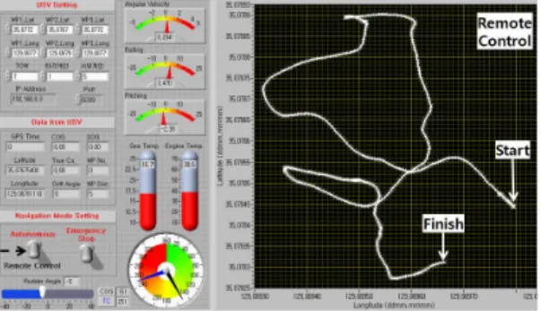
The initial navigation mode of the USV set a Remote Control mode. It is possible to change from Remote Control mode to Autonomous mode using the toggle switch of the "Navigation Mode Setting" as pointed by dashed arrow in Figure 3. The change principle of the navigation mode is as follows: The toggle switch is a Boolean variable having the True (1) or False (0) whenever it is clicked. The value (1 or 0) saved in the Boolean variable is converted into a character for the TCP/IP communication. The character is combined with other data by delimiter which is a blank in this program.
Finally, a frame is formed and transferred to the USV.
Figure 3: Control Station Program
2.3.1 Autonomous Mode
The autonomous algorithm developed through our previous study applied to the USV [6]. The algorithm features to use only GPS information. It is more suitable for the small USV. On the other hand, it can be easily affected by GPS error when the USV moves slowly. One of the features about this algorithm is that it makes the USV to aim for the waypoint instead of following to the course line as
seen in Figure 4. In other words, the algorithm reduces the drift angle comparing COG and true course every second. The reason the algorithm applies to the USV unlike conventional vessel is that the USV does not need a long range navigation plan because it changes course frequently for his own purpose.
Figure 4: Feature of USV navigation
2.3.2 Remote Control Mode
The USV is controlled by keyboard(← →
↑ ↓ keys) of the Control Station computer when the navigation mode is the Remote.
The rudder is controlled by left and right key, the RPM of engine is controlled by up and down key. The rudder is operated by servo motor which is indicating the specific angle according to the duty ratio of the PWM signal. For example, if the period of a pulse is 20ms and the rising pulse width is 1.5ms, the servo motor indicates the neutral position. The rising pulse width will be increased or decreased by 0.05ms whenever the direction key is pressed.
The RPM of AC motor is regulated by the amount of current provided by the ESC which is controlled by PWM signal.
For example, when the period of a pulse is 20ms and the rising pulse width is 1.0ms, the ESC is initialized. When the rising pulse width is over 1.0ms, the ESC starts to provide current to the AC motor.
Eventually, the RPM of the AC motor is
proportionally increased according to amount of current.
2.4 Marine Observation System
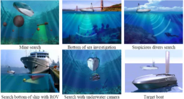
USV was developed for the military purpose in the early stage such as surveillance and reconnaissance. However, it has been studying a variety of other areas in these days. Figure 5 represents its availabilities proposed by J. Veers and V. Bertram[9]. In this study, assuming that the USV observes marine environment, the measurement of sea temperature using a thermosensor was conducted. After that, a distribution map of the sea temperature was made based on the data and GPS positions.
Figure 5: Application for USV
2.5 Self-Monitoring System
It is very important to improve the stability of USV by monitoring and controlling the condition of USV in real time. Therefore, two inclinometers and a gyro-sensor were installed on the USV in order to monitor three DOF motions (rolling, pitching, and yawing). Also, a temperature sensor was installed on the engine to measure the temperature.
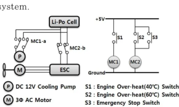
Figure 6 shows a sequence control circuit for self-monitoring of the propulsion
system.
Figure 6: Sequence Control of Propulsion System
In other words, S1, S2, and S3 in Figure 6 are a-contact switches which are operated by digital output of DAQ Board (NI USB-6210), which is controlled by LabVIEW program of the Control Station computer. MC1 and MC2 are relays operated by DC +5V. MC1-a and MC2-b are relay a-contact and relay b-contact respectively operated by MC1 and MC2.
For example, when a temperature of the engine is over 40°C, S1 is closed and then MC1-a is closed by MC1. The water pump finally is operated to cool the engine.
Meanwhile, when either a temperature of the engine is over 60°C or the 'Emergency stop' switch in Control Station program is clicked, S2 or S3 are closed respectively.
MC2-b is opened by MC2, and then the ESC finally stops providing the electricity to the engine.
3. Experiment and Result
3.1 Remote Control Test Using the TCP/IP Communication
Remote control test was conducted at the Long Beach in Korea Maritime University on June 28, 2009, as seen in Figure 7. The weather was cloudy. Some ripples on the surface were occurred because the average wind speed was 3.3㎧
at Busan. It was not difficult to remotely control the USV even though time delay about a second was occurred. Monitoring to USV had been carried out continuously with receiving the data from the GPS and sensors.
Figure 7: Sea trials area(left) and test(right)
3.2 Autonomous Navigation Test
Autonomous navigation test was conducted at the Harbor in KMU on June 30, 2009, as seen in Figure 8. The weather was cloudy. The surface was very calm because the average wind speed was 1.6㎧ at Busan. However, the inflow of sea current was observed. Autonomous navigation test was conducted with adjusting the proportional gain at the Control Station because it was easily affected by the circumstances (wind, sea current, and etc.). The result of the test was satisfied when the proportional gain set 0.3.
Figure 8: Sea trials area(left) and test(right)
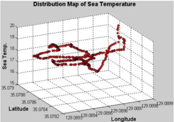
3.2 Measurement of Sea Temperature
Assuming that the USV observes marine environment, the test was carried out at the Long Beach in KMU on June 28, 2009,
as seen in Figure 7. The GPS data and sea temperature were stored as txt file format. A distribution map of the sea temperature was made using the Matlab 7.0. Figure 9 represents a distribution map of seawater temperature at the area.
Figure 9: Distribution Map of Sea Temperature
4. Conclusion
Our previous study on the USV was focused on the development of autonomous navigation algorithm. On the other hand, the operational aspects of the USV were somewhat overlooked. In this study, the followings were considered to monitor and control the USV. First, the TCP/IP communication using the wireless modem was applied to the USV. Second, the USV can be easily controlled by a keyboard(or joystick) of the Control Station.
In the meantime, assuming that the USV observes marine environment, the measurement of sea temperature was conducted, and a distribution map of the sea temperature was subsequently made.
If Multi-beam, Side Scan Sonar, or Echo-sounder is installed on the USV instead of the temperature sensor, it will be able to make the underwater map more
easily and to be applicable to the waterfront development, marine construction, and etc. Consequently, the observation using the USV can be more economic than it using the traditional method. The development of small USV like our study will be expected to contribute to observe marine environment economically and to advance practical use of the USV.
We discovered some following problems from the tests. First, it was not easy to control the USV by external circumstances such as wind, wave, current, and etc. at the autonomous mode. So, it will be necessary to improve the autonomous algorithm. Second, if the wireless communication was disconnected between the USV and Control Station, the program of the USV and the engine were stopped.
Then, it will be required to be reconnected with the wireless network instead of ending the program. Finally, the wireless communication range was about 4~500m.
It should be studied to expand the range of wireless communication in the future.
References
[1] S. Y. Boo, “A study on the conceptual design of an unmanned surface vehicle (USV),” The Korea Institute of Military Science and Technology, vol. 7, no. 3, pp. 59-68, 2004 (in Korean).
[2] The emerging UMV and UGV markets 2008~2018, Visiongain, 2008
[3] The growing US market for unmanned surface vehicles(USVs), Moire Inc., pp.
1-8, 2008
[4] H. W. Shim, B. H. Jun, P. M. Lee, Y.
G. Lim and J. H. Lee, “Dynamic
positioning of unmanned surface vehicle with two fixed thrusters”, The Korean Association of Ocean Science and Technology Society, pp. 2286-2289, 2008.
[5] N. S. Son, S. Y. Kim, S. H. Van and C.
M. Lee, “Design of an auto-navigation system of unmanned surface vehicle for close-range observation”, The Society of Naval Architects of Korea, pp. 63-68, 2004.
[6] H. I. Kim and S. H. Jun, “Development of autonomous navigation algorithm for very small unmanned surface vehicle based on GPS”, Journal of Navigation and Port Research, vol. 33, no. 5, pp.
303-308, 2009.
[7] E. T. Steimle and M. L. Hall,
“Unmanned surface vehicles as environmental monitoring and assessment tools”, OCEANS 2006, pp.
1-5, 2006.
[8] T. W. Vaneck, “Fuzzy guidance controller for an autonomous boat”, Control System Magazine, IEEE, vol.
17, no. 2, pp. 43-51, 1997.
[9] J. Veers and V. Bertram, Development of the USV Multi-Mission Surface Vehicle III, 2006.
Author Profile
Hyo-Il Kim
He received the B. E. degree at the Korea Maritime University. He is currently working toward the M. E.
degree.
Seung-Hwan Jun
He received the B. E. and M. E.
degrees from Korea Maritime University, and M. E. and Ph. D. degrees at Tokyo Institute of Technology, Japan.
He is currently a professor in the Division of Navigation Science at Korea Maritime University.
Serng-Bae Moon
He received the B. E. degree in Nautical Science from Korea Maritime University. He had been with the Hanjin Shipping Co., Ltd. as a navigation officer for around 4 years. He received the M. E. and Ph. D. degrees from Korea Maritime University. He is currently a professor in the Division of Navigation System Engineering at Korea Maritime University.