Chapter 11. Principles of Heat Flow in Fluids
Heat-Exchange Equipment
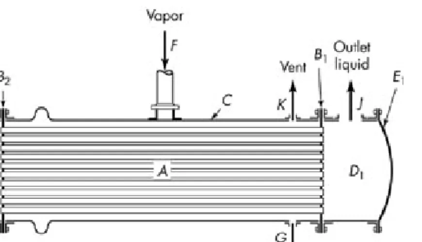
Fig. 11.1. Single pass tubular condenser:
A: tubes; B1, B2: tube sheets; C: shell; D1, D2: channels; E1, E2: channel covers; F: vapor inlet;
G: condensate outlet; H: cold-liquid inlet; J:
warm-liquid outlet; K: noncondensed gas vent.
Fig. 11.2. Temperature-length curves for condenser.
Approach: terminal T difference,
Range: T change of a fluid, Tcb-Tca, Tha-Thb
2 1, T T ∆
∆
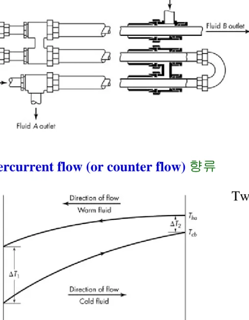
Fig. 11.3. Double-pipe heat exchanger.
* Countercurrent flow (or counter flow) 향류
approaches:
warm fluid range: Tha- Thb cold fluid range: Tcb- Tca
2 1, T T ∆
∆
Two fluids enter at different ends of HX.
“ pass in opposite directions.
* Parallel flows (or cocurrent flow) 병류
Two fluids flow in the same direction.
cf.) cross flow
교차류
Energy Balances
In heat exchangers, Ws, Ep & Ek ≈ 0.
q H
H
m & (
b−
a) =
mass flow rate
rate of heat transfer
enthalpies/mass at exit and entrance
For the warm fluid, For the cold fluid,
qc = -qh (Å The heat lost by the warm fluid is gained by the cold fluid) 0
)
( hb − ha = h <
h H H q
m&
0 )
( cb − ca = c >
c H H q
m&
q H
H m H
H
mh ha − hb = c cb − ca =
∴ & ( ) & ( )
: overall enthalpy balance
For a condenser,
cb pc cb
ca pc ca
hb ph hb
ha ph
ha c T H c T H c T H c T
H =λ + , = , = , =
[
ph( ha hb)]
c pc( cb ca)h c T T m c T T
m + − = −
∴ & λ &
latent heat
specific heat of the condensate
specific heat of cold fluid
Heat Flux and Heat-Transfer Coefficients
. Heat flux: the rate of heat transfer per unit area
. Average stream temperature (or mixing-cup temperature):
average temperature of fluid stream
* Overall heat-transfer coefficient (총괄 열전달계수) U
Driving force: Th– Tc (overall local temperature )∆T dA T
dq(localflux)∝∆
) (Th Tc U
T dA U
dq= ∆ = −
∴
local overall heat-transfer coefficient
--- Eq. (11.9)
o i o
i i
o
D D dA
dA U
U = =
Uo: overall heat-transfer coefficient based on outside surface area Ui: “ “ inside surface area
* Integration over total surface
Integration of Eq. (11.9) to the entire area of a heat exchanger Assumptions:
1) U --- constant 2) cpc, cph --- constant
3) heat exchange with ambient --- negligible
4) flow --- steady, either parallel or countercurrent
T vs. q in countercurrent flow (가정 2와 4 하에서의 그래프)
Tc & Th vary linearly with q. (가정 2와 4 적용)
Æ “ .
기울기 constant
∆T
qT
T T
dq T
d(∆ ) = ∆ 2 −∆ 1
rate of heat transfer in entire heat exchanger
TdA U
dq = ∆ 에 대입하면
qT
T T
TdA U
T
d( ) = ∆ 2 −∆ 1
∆
∆
적분:
T T
T
A AT
∆
∆
→
∆
→
for for 0
2 1
∆ ∫
−
= ∆
∫ ∆
∆ ∆
∆ AT
T T
T dA
q T T
U T
T d
0 1
2 )
( )
2 (
1
L T T
T UA T
T T
T UA T
q = ∆
∆
∆
∆
−
= ∆
∴ ln( 2/ 1)
1 2
logarithmic mean temperature difference (LMTD):
) /
ln( 2 1
1 2
T T
T T
∆
∆
∆
−
∆
* Individual heat-transfer coefficient (개별 열전달계수) h U depends on many variables.
Consider a specific point in double-pipe heat exchanger
& Assume turbulent flow
surface of tube – clear of dirt or scale Individual heat-transfer coefficient, h
Fig. 11.8. T gradients in forced convection Tw
T
dA h dq
= −/
average T wall T
heat flux
wh h
i i
T T
dA h dq
= −/
for the inside tube
for the outside tube
c wc o o
T T
dA h dq
= /−
1/h: thermal resistance cf.) xw/k for conduction
. Heat transfer very near the wall occurs only by conduction.
w w
w T T
dy k dT
dy h k dT dA
dq
− −
=
⎟⎟ ⇒
⎠
⎜⎜ ⎞
⎝
− ⎛
= ( / )
w w
T T
dy D dT
k hD
− −
= ( / ) T gradient at the wall
average T gradient across the entire pipe Nu (Nusselt number)
: the ratio of the total heat transferred to the heat by conduction D
T T
dy dT
w w
/ ) (
) /
~ (
−
. Another interpretation of the Nusselt number
If all the resistance to heat transfer is in a laminar layer of thickness x in which heat transfer is only by conduction.
∴
=
=
=
− =
=
x D k D x k k hD
x h k x
T T k dA
dq w
Nu
) (
the ratio of the tube diameter to the equivalent thickness of the laminar layer
* Calculation of overall coefficients from individual coefficients From Fig. 11.8,
Fig. 11.8. T gradients
⎟⎟⎠
⎜⎜ ⎞
⎝
⎛ + +
=
∆
=
−
=
− +
− +
−
o o m
L w i
i
c h c
wc wc
wh wh
h
h dA k
A d
x h
dq dA
T T
T T
T T
T T
T
1 1
) (
) (
) (
tube wall thickness thermal conductivity of wall . Heat flux based on the outside area
o L
o m w i
o i
c h
o L
o m
w i
o i
c h o
h D
D k
x D
D h
T T
h A
d dA k
x dA
dA h
T T dA
dq
1 1
1 1
⎟⎟+
⎠
⎜⎜ ⎞
⎝ + ⎛
⎟⎟⎠
⎜⎜ ⎞
⎝
⎛
= −
⎟⎟+
⎠
⎜⎜ ⎞
⎝ + ⎛
⎟⎟⎠
⎜⎜ ⎞
⎝
⎛
= −
o L o m w i
i o
o D h
D k
x h D
D U
1
1 = + +
∴ ln( o / i)
i L o
D D
D D = D −
. Heat flux based on the inside area 앞과 마찬가지로 정리해 보면,
o o
i L
i m w i
i D h
D D
D k
x h
U = + +
∴ 1 1
. Overall temperature drop
. Temperature drop in two fluids & wall individual resistances
T U1
)
(∆ ∝
∝
o o L
o m w
w i
i o
i
o h
T D
D k x
T h
D D
T U
T
/ 1 ) / )(
/ ( /
/ 1
= ∆
= ∆
= ∆
∆
T drop through inside fluid
T drop through outside fluid
T drop through metal wall Eq. (10.13)과 같은 resistance 형태:
C C B
B A
A
R T R
T R
T R
T = ∆ = ∆ = ∆
∆
. Overall resistance,
o L o m w i
i o o
o D h
D k
x h D
D
R =U1 = + + 1
* Fouling factors (오염계수)
Actually, heat-transfer surfaces do not remain clean – Scale, dirt & solid deposits form.
Æ provide additional resistances to heat flow Æ reduce the overall coefficient
hdi, hdo: the fouling factors for the scale deposits on the inside & outside tube surfaces Then,
--- Eq. (11.37) and
--- Eq. (11.38)
Fouling factors --- a safety factor for design
) / 1 ( ) / 1 ( ) / )(
/ ( ) /
( ) /
(
1
do o
L o m w i
i o di
i o
o D D h D Dh x k D D h h
U = + + + +
) /
( ) /
( ) / )(
/ ( ) / 1 ( ) / 1 (
1
do o i o
o i L
i m w i
di
i h h x k D D D D h D D h
U = + + + +
Ex. 11.1) MeOH flowing in the inner pipe of a double-pipe exchanger is cooled with water.
methanol water
ri
xw
ro
steel pipe wall F) Btu/ft
26
(km = 2⋅o
. 1 inch Schedule 40 steel pipe:
(from Appendix 3) Di= 0.0874 ft Do = 0.1096 ft xw = 0.0111 ft
(Do-Di)/2 . h & hd: Table 11.1
What is the overall coefficient, based on the outside area of the inner pipe ? (즉, Uo=?) (Ans.)
ft 0983 . 0 . . ) . / (
ln − = =
=
i o
i L o
D D
D D D
F h Btu/ft 80.9
(11.37) Eq.
from
o 2 ⋅ ⋅
=
←
o = U
* Special cases
In the special case that
Fouling effects are negligible
Metal wall is very thin (i.e., large-diameter thin-walled tube)
Then,
1
/ ≅
→ Do Di
i m
w o i
o U h x k h
U 1/ / 1/
1 +
= +
=