Cementless total hip arthroplasties were introduced to improve the long-term durability of the implants8,9,13). Of the cementless femoral components available, some rely on distal or diaphyseal fixation, whereas others rely on proximal or metaphyseal fixation. The rationale for the design of the
latter group of femoral components is to transfer hip joint reaction forces to the most proximal part of the femur to re- duce stress shielding related bone resorption, which will take place in the proximal femur after total joint replacement. The rationale for the design of the former group of femoral com- ponents is to achieve a firm fixation of the stem in the strong diaphyseal cortical bone. However, Ohl et al.11)emphasized that tight stem fixation should be obtained in both meta- physeal and diaphyseal regions to achieve clinical success.
The purpose of this study was to compare the results of
508 508
Finite Element Analysis and Torsional Stability Testing of Reference (Metaphyseal and Diaphyseal Fixation) and Experimental
(Metaphyseal Fixation Only) Cementless Femoral Stems
Young-Hoo Kim, M.D.
The Joint Replacement Center of Korea, Ewha Womans University College of Medicine, Seoul, Korea
508 508 Address reprint requests to
Young-Hoo Kim, M.D.
The Joint Replacement Center of Korea at Ewha Womans University Dong Dae Mun Hospital, 70 Jongro 6-ga, Jongro-gu, Seoul 110-783, Korea
Tel: +82.2-760-5000, Fax: +82.2-760-5601 E-mail: [email protected]
Purpose: To report the details of the findings of finite element analysis and torsional stability testing of a reference stem (fixation in both metaphysis and diaphysis) and an experimental stem (fixation in the metaphysis only).
Materials and Methods: Finite element ABAQUS software (version 5.5) was used for all analyses. A Newton Raphson iterative solution scheme was used to calculate the nodal displacements and to solve the contact equations. Finite element models of the reconstructed proximal femur were developed. A model of bone geometry was developed from the digitized sections of a right adult human femoral spec- imen. Two femoral stems (reference and experimental stems) were designed in accordance with the bone geometry. Rotational micromotion of the implant relative to the proximal femoral cortical surface was measured using a single, linearly variable differential transducer (LVDT). Three piezoelectric transduc- ers were used to detect the displacement of the stem in the femur.
Results: Under all interface conditions, the compressive stresses of the coating surface were below 1.5 MPa. Shear stresses in the two friction models were below 0.5 MPa, and below 1 MPa in the bonded model.
The stress exerted over the cortex in the experimental model was 50% of that in the reference model. The relative displacement of the stem in the coated region was less than 0.05 mm, but it increased distally in a linear fashion and was 0.45 mm at the stem tip. A stress concentration in the proximal femoral cancel- lous bone was noticeably higher in the experimental model than in the reference model. However, the overall characteristics of stress transfer were not changed by stem shape modification. Experimental stem was found to have significantly less rotational micromotion and total permanent rotational displace- ment values (between 10 and 29 N∙m) than the reference stem.
Conclusion: The torsional stability of the experimental stem is enhanced by: increasing stem thickness in the anteroposterior plane; adding a lateral flare to the stem; and a congruent fit between the proximal medial portion of the stem and calcar femorale. A role of short and tapered distal stem of the experimental stem was negligible in providing with the stem stability and, therefore, the femoral distal stem can be removed.
Distal stem removal can minimize stress shielding related bone resorption and can avoid thigh pain.
Key Words: Reference femoral stems, Experimental femoral stems, Finite element analysis, Torsional stability test
finite element analysis and torsional stability test between a reference stem (fixation in both metaphysis and diaphysis) and an experimental stem (fixation in metaphysis only).
MATERIALS AND METHODS
1. Finite element analysis
Finite element models of reconstructed proximal femur were developed1-4,6). A bone geometry model was developed using the digitized sections of a right adult human femur specimen. Two femoral stems (reference and experimental stem) were designed in accordance with the bone geometry.
1) Bone geometry
The finite element models of cortical and cancellous bones were generated from scanned sections4).
2) Implant geometry
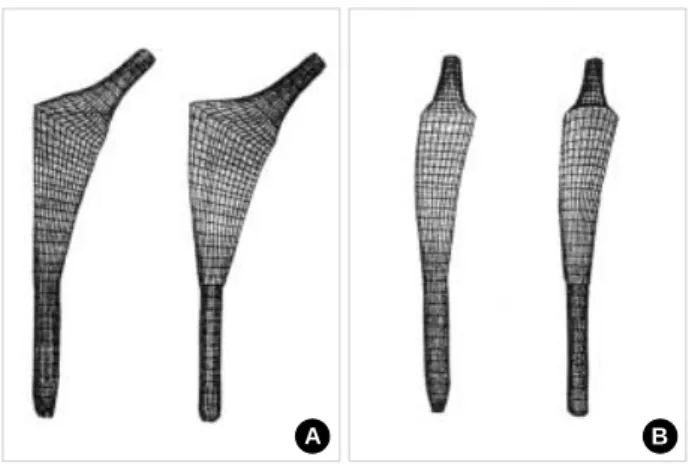
The finite element meshes of the implants were developed in accordance with bone geometry and the stem shape was constructed18). Each stem consisted of an inner core of 6-noded linear wedge elements, which were surrounded by two rings of 8-noded bilinear brick elements, with a total of approxi- mately 5000 elements per stem. Frontal and lateral shapes of two finite element models were constructed (Fig. 1).
Element stiffness is described in accord with the assumed strain formulation12). The accuracy of this approach was con- firmed by a convergence test for a bonded proximal stem and an unbonded distal stem-tip (the 8-node brick elements were converted to quadratic 20-node elements).
3) Interface conditions
Interactions were modeled using the Coulomb friction law10). For each model, three interface conditions were sim- ulated as follows: (A) Unbonded and uniform friction prop- erties over the entire implant surface. A friction coefficient value of 0.3 was assumed between the implant and the sur- rounding bone; (B) Unbonded and increased friction coef- ficient in the region of the porous coating. Rancourt et al.12) experimentally determined the coefficient of friction at the interface between the porous coating and the bone as between 0.4 and 0.8. A value of 0.6 was used in all analyses in the present study; and (C) Bonded in the region of the porous coating and unbonded (uniform frictional model) over the remainder of the implant surface. The bonded in the porous coating region simulated complete bone ingrowth over the entire coated region. Furthermore, no shear or tensile stress limit was imposed on the bonded region. Therefore, any magnitude of shear or tensile stress could be transmitted across this interface.
4) Material properties
The femur was modeled as a linear elastic tubular struc- ture composing of isotropic bone (a modulus of elasticity of 14.0 gigaPascals, and a Poisson’s ratio of 0.3). A segment of the femur, 140 mm long, was modeled and the most proxi- mal surface was inclined 40°medially from the horizontal plane. A region of cancellous bone in the greater trochanter was assigned as a modulus of elasticity of 0.32 gigaPascals and a Poisson’s ratio of 0.3. The elastic modulus of titanium was assigned as 110 gigaPascals. Cross sections of the femur were symmetrical about a mediolateral axis. The distal por- tion of the femur was fixed.
5) Loading
The loading conditions were simulated that occur during the single-legged stance phase of gait5,7). The system of forces in the hip was resolved into a reaction force on the femoral head and a tensile force in the abductor muscles. In this anal- ysis, the femoral shaft was inclined at an angle of 12°to the vertical axis in the frontal plane. To calculate the forces in the joint for a person of weight 60 kg, the mass of the sup- porting leg was subtracted, which resulted in a spinal load of approximately 450 N. This load produced a femoral head reaction force (FH) of 1,460 N, acting at an angle of 20°,
Fig. 1.Finite element models of experimental and reference fe- moral stems. (A) Frontal view of the two femoral stems. (B) Lat- eral view of the two femoral stems.
A B
when measured clockwise from the femoral shaft axis in the frontal plane. The force had components of 784 N, 117 N and -1,346 N in the X, Y and Z directions, respectively. The abductor muscles had a resultant stabilizing force (FT) of approximately 800 N, acting at an angle of 26°, with com- ponents of -117 N, -382 N and 784 N in the X, Y and Z directions, respectively.
The femoral head geometry was not modeled, as it did not influence stress transfer from the component to the bone.
Therefore, the femoral head reaction force was applied to a node located at the center of the femoral head. Surface nodes on the section of the femoral neck were also linked to the node at the center of the femoral head. Hence, the reaction force was shared over this region, and thus simulated the presence of a rigid prosthetic head, as shown in Fig. 2.
6) Boundary conditions
The model was constrained only at the distal end of the cortex. All nodes at this end were constrained in the verti- cal direction. The base of the cortex was constrained from rigid body motion by dividing the cortex into four regions, as shown in Fig. 3, and by constraining the nodes so that they were unable to cross the boundary divisions. This arrange- ment prevented the rotation of the cortex at this point. By applying nodal constraints in this way, the cortex was free to expand or contract as it would do in a natural joint.
7) Analysis procedure
The finite element program ABAQUS (Version 5.5) was used for all analyses (Hibbit Karlsson and Sorensen, Inc, Paw- tucket, Rhode Island, USA), and a Newton Raphson itera- tive solution scheme was used to calculate nodal displace-
ments and to solve the contact equations. Contact behavior required the most computing time in these analyses.
2. Torsional stability test
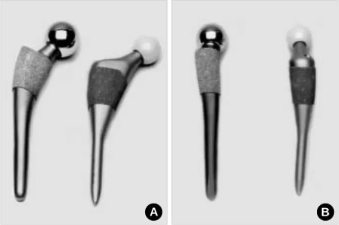
Ten preserved human femoral specimens were selected and divided into two groups of five. A reference noncemented anatomic stem (DePuy, Leeds, UK) was implanted in five speciemens and an experimental noncemented anatomic stem (DePuy, Leeds, UK) was implanted in the remaining five speciemens (Fig. 4). All stems were manufactured of Ti-alloy. All stems were implanted by one surgeon (YHK) to minimize implantation technique variability. Each spec-
Fig. 4.Anteroposterior and lateral views of a reference and of an experimental noncemented anatomic stem. (A) Anteroposterior view of a reference and an experimental stem. The diameter of the experimental stem is markedly reduced distally and the medi- al part of the proximal stem is more curved, which probably will ensure a closer cortical fit in the calcar region. Moreover, the lateral part of the stem is designed to fit the lateral flare of the femur. (B) Lateral view of a reference and of an experimental stem. The diameter of the distal experimental stem is markedly reduced and the anteroposterior diameter of the proximal stem is substantially increased compared to the reference stem.
A B
Fig. 2.Application of the femoral head reaction force.
Neck of the stem
Rigid surface node
Femoral head reaction force FH
Rigid surface elements
Fig. 3.Boundary conditions at the distal tip of the cortex.
Y
X
imen was carefully inspected for fractures, both visually and radiographically. Fractured specimens were excluded from the mechanical testing.
Each specimen was then potted in dental cement and fixed to a special driver. They were then mounted in a servohy- draulic testing machine (Model 1321, Instron, Canton, Mas- sachusetts, USA) so that the long axis of the femoral implant and rotational axis of the Instron were colinear.
Rotational micromotion of the implant relative to the prox- imal femoral cortical surface was measured using a single, linearly variable differential transducer (LVDT) (LBB-375- PA-060, Scheevitz, Pensauken, New Jersey, USA). The LVDT was attached to the calcar femorale, and a flag was attached to the medial edge of the femoral implant just above the cut edge of the calcar femorale. The LVDT measurement point was always located on the flag 35 mm from the centerline of the stem.
The femoral neck was grasped using a specially made clamp, and torsional load was applied using a servohydraulic machine. LVDT and torque cell output were recorded on a chart recorder (Model 9500 Astromed, Westwarwick, Rhode Island, USA). Rotational micromotion of the implant rela- tive to the proximal femoral inner cortical surface was mea- sured in micrometers. Rotational micromotion was defined as deformation recovered after each load was released. Per- manent rotational displacement was defined as that displace- ment at which the implant failed to recover after load release.
Since different sizes of femoral implants were used in this study, it was necessary to calculate the exact linear displace- ment at the medial bone-prosthesis interface rather than take the actual displacement measured on the flag attached to the implant.
Although the actual rotational micromovement cannot be measured using linear units, the measured linearly values could be considered to be equivalent to the amount of actu- al rotational micromovement, because the implant angles of rotation were very small.
Each specimen was subject to a two-part loading regimen.
Torsion was applied in internal rotation at 0.1 Hz using a ramp wave form. Peak torsion was maintained for 5 seconds before it was returned to zero. Each femur model was sub- ject to 11 cycles. The first torsion cycle at 4.9 N.m, with subsequent cycles performed in 2.45 N.m increments to give a maximum torque of 29.4 N.m. After each loading
cycle, a slope test was performed to detect component loos- ening. This test consisted of a 4.9 N.m torsional load applied to the stem in internal and external rotation and measured implant loosening with respect to the previous cycle.
Three piezoelectric transducers (CR 15, Physical Acous- tics, Lawrenceville, New Jersey, resonant frequency=150 kHz) were coupled to the specimen with ultrasonic gel and held in place with electrical tape. The transducers were placed on the proximal femur (channel 1), the distal femur (chan- nel 2), and on a waveguide on the end of the implant neck (channel 3). Detected AE signals were sent through pream- plifiers (1220-100-300-6P-PAC) and amplified to 40 dB before entering the acquisition system (Locan-AT, PAC).
These signals were stored on floppy disks for later analysis.
Only the output from channel 1 was used during the data analysis. Statistical analysis was performed using the unpaired, two-tailed tests to compare deflection statistics.
RESULTS
1. Finite element analysis
1) Contact stresses in the proximal stem
Under all interface conditions, the compressive stresses of the coated surface were below 1.5 MPa. Shear stresses in the two friction models were below 0.5 MPa, and below 1 MPa in the bonded model. Negative (tensile) stresses were devel- oped in some regions of the unbonded interface, and these tensile stresses were somewhat higher in the experimental models (up to -3.7 MPa) than in the reference models (-1.7 MPa) (Fig. 5, 6).
The peak contact stresses were lower (by 14-27%) in the nonuniform friction models (B) than in the uniform friction models (A), and were 50% lower than in the bonded mod- els. Conversely, as was expected, highest shear stresses were observed in the bonded interface condition, though these dropped considerably (by 27-48%) when relative slippage was allowed with a friction coefficient of 0.6. Further reduc- tions in peak contact shear stresses occurred (8-30%) when the friction coefficient in the coating region was reduced from 0.6 to 0.3.
2) Contact stresses in the distal stem
The peak stresses at the distal stem tip are shown in Fig.
7. Both the implant design modification and the interface condition had a noticeable influence on the magnitude of
the stresses. The smooth decline in stress magnitude at the stem tip in the experimental model indicates that both the addition of lateral flare and the distal stem diameter reduc- tion contributed to lowering the contact stress at the stem tip. The contact stress exerted over the cortex at the stem tip in the experimental model was 50% of that in the ref- erence model.
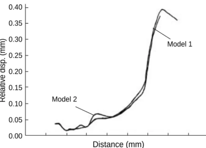
3) Relative displacement
Displacements of the implant relative to the surround- ing bone are shown in the path plots (Fig. 8, 9). The trend of displacement was the same for both implant models and interface conditions. The relative displacement of the exper- imental stem was less than that of the reference stem (less than 0.3 mm). Also, the relative displacement of the stem in the coated region was small (less than 0.05 mm), but it increased distally in a linear fashion and was approximately 0.45 mm at the stem tip. The relative displacement of the
stem at the stem tip region was predominantly elastic.
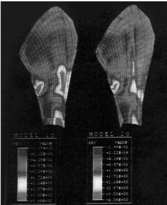
4) Cancellous bone stresses in proximal femur
Maximum tensile and twice maximum shear (TRESC) stresses in cancellous bone are illustrated in the posterior and
Fig. 5.Bonded interface, lateral surface contact pressures.
Contact pressure (MPa)
5.00
4.00
3.00
2.00
1.00
0.00
-1.00
Distance (mm) Model 1
0.00 50.00 100.00 150.00 200.00
Model 2
Fig. 7.Distal peak contact pressures.
Peak disital pressure (MPa)
18.0 16.0 14.0 12.0 10.0 8.0 6.0 4.0 2.0 0.0
Model 1 Model 2
Union fraction Non unionfraction Bonded
Fig. 6.Bonded interface, medial surface contact pressures.
Contact pressure (MPa)
6.00 5.00 4.00 3.00 2.00 1.00 0.00 -1.00 -2.00 -3.00 -4.00
0.00 20.00 40.00 60.00 80.00 100.00120.00140.00160.00180.00 Distance (mm)
Model 2
Model 1
Fig. 8.Bonded interface, relative displacement at lateral surface.
Relaitive disp. (mm)
0.45 0.40 0.35 0.30 0.25 0.20 0.15 0.10 0.05 0.00
Distance (mm) Model 1
Model 2
Fig. 9.Bonded interface, relative displacement at medial sur- face.
Relaitive disp. (mm)
0.40 0.35 0.30 0.25 0.20 0.15 0.10 0.05 0.00
Distance (mm)
Model 1
Model 2
anterior contour plots for both models and for all three inter- face conditions (Fig. 10, 11).
A stress concentration in the proximal femoral cancellous bone was noticeably higher in the experimental model than in the reference model.
Although the reference model had slightly lower peak ten- sile and shear stresses in the cancellous bone of the proximal femur than the experimental model, the overall characteris- tics of stress transfer were not changed by stem shape mod-
ification. The reduction of the distal stem diameter caused a negligible difference in tensile and shear stresses in can- cellous bone of the proximal femur.
2. Torsional stability test
When rotational micromotion was compared in the two groups, the experimental stem was found to have significant- ly (p<0.05) less micromotion than the reference stem between 10 and 20 N.m (Fig. 12). When total permanent rotational
Fig. 10.Bonded interface, posterior cancellous bone, twice maxi- mum shear stresses.
Fig. 11.Bonded interface, anterior cancellous bone, twice max- imum shear stresses.
Micromovement (microns)
800 700 600 500 400 300 200 100 0
5 10 15 20 25 30
Reference stem
Experimental stem
Fig. 12.Rotational micromovement versus torque.
Torque (NM)
Micromovement (microns)
600
500
400
300
200
100
0
5 10 15 20
Reference stem
Experimental stem
Fig. 13.Permanent rotational displacement versus torque.
Torque (NM)
displacement values were compared, the experimental stem was also found to be significantly better (p<0.05) than the reference stem between 10 and 29 N.m (Fig. 13). These findings indicate that a reference stem showed significant- ly more micromotion at all torque levels than the experimen- tal stem. Also, the total permanent rotational displacement was significantly (p<0.05) greater in the reference stem than in the experimental stem.
DISCUSSION
The results of this study demonstrated that, in both the experimental and reference models, the hip joint load was transferred evenly to the cancellous bone of the proximal femur. While the relative displacement of the implant in the porous coated region was negligible, it was high in the distal portion of the stem. The increase in stem displacement in the distal portion resulted from femoral cortex compaction by a femoral stem under axial load. The displacement of the stem was elastic and recoverable. There was no evidence of implant subsidence. Contrary to expectation, the implant geometry modification and the change in interface condi- tions had negligible effects on the relative displacement of the stem in the bone.
Although the peak contact stress values in cancellous bone were slightly different in the experimental and reference models, the overall characteristics of the stress transfer were essentially the same in both models. The presence of lateral flare in the experimental model did, however, potentiate higher loading in the proximal femur.
Reduction of the distal stem diameter from 12 mm to 10 mm had little influence on the stress transfer to the proxi- mal femur. However, the combination of a distal stem diam- eter reduction and the presence of the lateral flare contribut- ed to more physiological loading in the proximal femur and to lowering contact pressure in the region at the distal stem.
This finding was the most favorable scenario since it could reduce stress shielding related proximal bone resorption and reduce the prevalence of thigh pain.
Bending stresses in the cortex were unaffected by implant geometry and interface condition variations. These findings suggest that the modes of global deformation in the recon- structed joint were not affected significantly by these vari- ables.
By increasing the coefficient of friction from 0.3 to 0.6 in
the coating region, contact stresses were reduced, but shear stresses were correspondingly increased. However, the over- all pattern of stress transfer was not altered significantly by changing the coefficent of friction.
Bonding the interface in the region of the porous coat- ing resulted in an approximately 50% reduction in peak contact stress along both the medial and lateral surfaces of the proximal femur. However, the reduction of contact stress increased shear stress in the proximal femur, particularly on the lateral side (peak shear stress increased to 3). Also, tensile stress was generated in the distal part of the coated region13). The presence of the lateral flare increased contact stress in the proximal lateral region of the femur. Therefore, major stress transfer in the experimental model with a reduced distal stem diameter occurred noticeably in the proximal medial and proximal lateral regions of the femur.
Several authors have reported that rotational micromo- tion of the femoral stem is minimized by tight fixation in both metaphysis and diaphysis14-17). Ohl et al.11)found that tight proximal and distal fixation is necessary to control both rotational micromotion and permanent rotational displace- ment caused by torsional loading. Theoretically, mechani- cal fixation of the reference stem should be excellent because it had tight fixation in both metaphysis and diaphysis. How- ever, the findings of the current study demonstrate that the reference stem had more rotational micromotion than the experimental stem had. This finding suggests that rotation- al micromotion of the stem can be developed despite the fact that the smooth distal portion of the reference stem remains tightly fixed in the diaphysis. On the contrary, although the experimental stem was fixed only in the metaphysis, the rotational micromotion of the experimental stem was min- imal. This finding emphasizes that tight fixation of the stem in both coronal and sagittal planes of the metaphyseal region of femur is crucial to achieve the rotational stability of stems in both reference and experimental models.
This study concludes that the torsional stability of the experimental stem is enhanced by following factors: increas- ing stem thickness in the anteroposterior plane; adding a lateral flare to the stem; and a congruent fit between the proximal medial portion of the stem and calcar femorale.
ACKNOWLEDGMENTS
The author would like to express his thanks to Greg Starke,
Ph.D. at University of Cape Town, South Africa for his com- puter work.
REFERENCES
1. Bathe KJ: Finite element procedure. 1st ed. Englewood Cliffs, NJ, Prentice Hall: 15-35, 1996.
2. Cristofolini L, Viceconti M, Capello A and Toni A: Mechan- ical validation of whole bone composite femur models. J Biomech, 29: 525-535, 1996.
3. Crowninshield RD, Johnston RC, Andrews JG and Brand RA:A biomechanical investigation of the human hip. J Biomech, 11: 75-85, 1978.
4. Dalstra M, Huiskes R and Van Erning L: Development and validation of a three-dimensional finite element model of the pelvic bone. J Biomech Eng, 117: 272-278, 1995.
5. Davy DT, Kotzar GM, Brown RH, et al: Telemetric force mea- surements across the hip after total arthroplasty. J Bone Joint Surg, 70-A: 45-50, 1988.
6. Huiskes R and Chao EYS: A surgery of finite element analysis in orthopaedic biomechanics: the first decade. J Biomech, 16: 385- 409, 1983.
7. Huiskes R and Verdonschot N: Biomechanics of artificial joints- the Hip. In: Mow VC, Hayer WC(eds). Basic orthopaedic biome- chanics, Ed 2. New York, Raven Press 1997.
8. Keaveny TM and Bartel DL: Effects of porous coating and col- lar support on early load transfer for a cementless hip prosthesis. J Biomech, 26: 1205-1216, 1993.
9. Keaveny TM and Bartel DL: Mechanical consequences of bone ingrowth in a hip prosthesis inserted without cement. J Bone Joint
Surg, 77-A: 911-923, 1995.
10. Mann KA, Bartel DL, Wright TM and Burstein AH: Coulomb frictional interface in modeling cemented total hip replacements: a more realstic model. J Biomech, 28: 1067-1078, 1995.
11. Ohl MD, Whiteside LA, McCarthy DS and White SE: Tor- sional fixation of a modular hip component. Clin Orthop, 287: 135- 141, 1993.
12. Rancourt D: Friction properties of the interface between porous- surfaced metals and tibial cancellous bone. J Biomed Mater Res, 24:
1503-1519, 1990.
13. Skinner HB, Kim AS, Keyak JH and Mote CD: Femoral pros- thesis implantation induces changes in bone stress that depend on the extent of porous coating. J Orthop Res, 12: 553-563, 1994.
14. Sugiyama H, Whiteside LA and Engh CA: Torsional fixation of the femoral component in total hip replacement: the effect of sur- gical press-fit technique. Trans Orthop Res Soc, 36: 258, 1990.
15. Sugiyama H, Whiteside LA and Kaiser AD: Examination of rotational fixation of the femoral component in total hip arthro- plasty: a mechanical study of micromovement and acoustic emis- sion. Clin Orthop, 249: 122-128, 1989.
16. Whiteside LA, Amador D and Russell K: The effects of the collar on total hip femoral component subsidence. Clin Orthop, 231: 120-126, 1988.
17. Whiteside LA and Easley JC: The effect of collar and distal stem fixation on micromotion of the femoral stem in uncemented total hip arthropalsty. Clin Orthop, 239: 145-153, 1989.
18. Zienkiewicz OC: The finite element method. 2nd ed. London, McGraw-Hill Book Company 85-98, 1977.
목 적: 골간단부와 골간부를 모두 고정한 대조군과, 골간단부만을 고정한 실험군에서 finite element 분석과 비틀림 안정성 시험 결과를 상세히 보고한다.
대상 및 방법: 모든 분석에 finite element 프로그램 ABAQUS 소프트웨어(version 5.5)를 사용하였다. 흔들림을 계산하고, 접점방정식을 풀기위해 Newton Raphson iterative solution 도식을 사용하였다. 재건된 근위대퇴의 finite element 모델 을 만들었다. 성인의 우측대퇴 표본을 계수화한 절편으로 골형상의 모델을 얻을 수 있었다. 골형상과 일치하는 두개의 대 퇴시스템(대조군과 실험군)을 디자인하였다. 근위대퇴골피질 표면에 대한 삽입물의 회전미세운동을 하나의 linearly vari- able differential transducer (LVDT)를 사용하여 측정하였다. 대퇴골 내에서 스템의 전위를 측정하기 위해 3개의 piezo- electric transducer를 사용하였다.
결 과: 근위대퇴골 피질과 대퇴시스템의 모든 경계면 상태에서 대퇴스템의 근위피복부의 접촉 stress는 1.5 MPa 이하이었 다. 두 접촉 대퇴스템의 전단 stress는 0.5 MPa 이하였고 근위피복부의 전단 stress는 1 MPa 이하이었다. 원위대퇴골의 내 측피질에 가해지는 접촉압력이 실험군에서 대조군의 50% 정도이었다. 대퇴스템의 대퇴골 내에서의 상대적 전위거리는 대퇴스템의 피복부에서 0.05 mm이었으며 윈위부에서 일차직선으로 증가하여 대퇴스템의 끝 부분에서는 0.45 mm이었 다. 실험군에서 대퇴골 근위부 내외 전후 측면으로 stress가 현저히 증가하였으나 대조군에서는 stress의 증가가 덜 현저하 였다. 전반적인 stress 전이는 대퇴스템 모양 변혁만으로는 영향을 받지 않았다. 실험 스템에서 대조스템에 비교하여 회전 미세운동과 영구회전전위가 두드러지게 줄었다.
결 론: 실험군의 대퇴스템의 비틀림 안정성은 대퇴스템의 전후면의 스템 두께의 증가, lateral flare를 대퇴스템에 첨가하는 것과 대퇴골의 calcar femorale와 대퇴스템의 밀접한 접촉에 의해 증가하였다. 실험군의 짧은 원위스템은 대퇴스템의 안정 성에는 크게 공헌하지 못하므로 대퇴스템의 원위스템은 제거하여도 대퇴스템의 안정성에는 영향이 없을것으로 사료되고, 원위스템을 제거하므로서 stress shielding에 의한 뼈의 흡수를 감소시킬 수 있으며 또한 대퇴부 통증을 감소시킬 수 있다.
색인 단어: 대조대퇴스템, 실험대퇴스템, Finite element분석, 비틀림 안정성시험
무시멘트 대퇴스템의 대조군(골간단부와 골간부 고정)과 실험군 (골간단부만의 고정)에서의
finite element
분석과 비틀림 안정성 시험김영후
이화여자대학교 의과대학, 한국인공관절센터