Design and Implementation of a MIMO Antenna for LTE700/2300/2500/PCS/Wibro/Bluetooth/Wimax
Mobile Handset
Yeon Chan Hong
*, Seong Ha Lee
*, Woon Geun Yang
*★Abstract
In this paper, we designed and implemented the MIMO (Multiple-Input Multiple-Output) antenna for the mobile handset that could be used for multiple services. Simulation results were obtained using SEMCAD X by SPEAG based on the FDTD (Finite Difference Time Domain) Method which showed that S11 values were less than -6 dB (VSWR < 3) for LTE (Long Term Evolution) 700/2300/2500, K-PCS (Korea-Personal Communication Service : 1,750 ∼ 1,870 MHz), US-PCS (US-Personal Communication Service : 1,850 ∼ 1,990 MHz), Wibro (2,300 ∼ 2,390 MHz), Bluetooth (2,400 ∼ 2,483 MHz), and US-WiMAX (US-World interoperability for Microwave Access:
2,400 ∼ 2,590 MHz) frequency bands. Measured results of the fabricated antenna also showed that it could be used for LTE 700/2300/2500, K-PCS, US-PCS, Wibro, Bluetooth, and US-WiMAX. services.
Key words: LTE, MIMO Antenna, antennas, mobile handset, monopole antenna
* Dept. of Electronics Engineering, University of Incheon
★Corresponding author
※ Acknowledgement
- This work was supported by University of Incheon Research Grant in 2011.
- Thanks to SPEAG for providing free license of SEMCAD X used in this study
Manuscript received May 22, 2012 ; revised July 1, 2012 ; accepted July 12, 2012
I. Introduction
The LTE(Long-Term Evolution) operation is in demand for modern mobile devices such as the smart phones, laptop computers, and tablet computers. The LTE operation can provide a much higher communication data rate than the WWAN (Wireless Wide Area Network) operation and mainly includes three operation bands of the LTE 700 (704 –787 MHz), LTE 2300 (2300–2400 MHz), and LTE 2500 (2500–2690 MHz)[1-2].
These antennas which can cover all the operating bands of the WWAN and LTE operations are attractive for use in mobile devices as the main internal antenna for voice and data communications.
However, it is noted that the LTE is best suited for the multiple-input multiple-output operation[2-3].
A small sized eight-band LTE 700/2300/2500, K-PCS (Korea-Personal Communication Service, 1750 – 1870 MHz), US-PCS (US-Personal Communication Service, 1850 – 1990 MHz), Wibro (2300 – 2390 MHz), Bluetooth (2400 – 2485 MHz), WiMAX(US-World interoperability for Microwave Access: 2,400 - 2,590 MHz) antenna will be very attractive for the LTE MIMO (Multiple-Input Multiple-Output) operation in the mobile devices. In regards to published papers, however, there are very few promising LTE antennas that occupy a small volume and are capable of covering all the LTE 700/2300/2500, K-PCS, US-PCS, Wibro, Bluetooth, WiMAX bands for mobile device applications[3].
Furthermore, there is a great demand for reducing the handset size, which remains relatively large in modern mobile handsets due to the presence of various integrated components for different applications. Therefore, small sized multiband internal antennas for wireless terminals are an emerging trend in the mobile handset industry[4].
In this paper, we propose a MIMO antenna for wideband operation covering LTE 700/2300/2500,
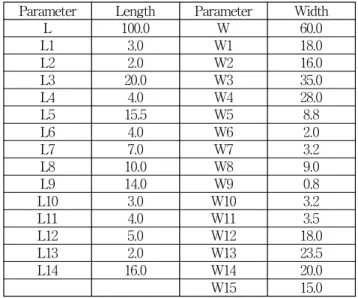
Parameter Length Parameter Width
L 100.0 W 60.0
L1 3.0 W1 18.0
L2 2.0 W2 16.0
L3 20.0 W3 35.0
L4 4.0 W4 28.0
L5 15.5 W5 8.8
L6 4.0 W6 2.0
L7 7.0 W7 3.2
L8 10.0 W8 9.0
L9 14.0 W9 0.8
L10 3.0 W10 3.2
L11 4.0 W11 3.5
L12 5.0 W12 18.0
L13 2.0 W13 23.5
L14 16.0 W14 20.0
W15 15.0
Fig. 1 shows the geometry of the proposed MIMO antenna. Also, the parameters of the proposed antenna are presented in Table 1. The antenna size of example design is 51 mm(W) × 20 mm(L) × 5 mm(H). For the design studied here, the antenna is
(a)
proposed antenna is composed of two branches. And one branch has a rectangular slit. In case of monopole antenna, the basic antenna size is calculated as λ/4. Short left branch covers middle and high bands and long right branch covers low band.
Design parameters are optimized using electromagnetic simulator. And based on the obtained results, a folded monopole antenna is implemented.
Table 1 shows values of the design parameters which were derived through the simulation.
Table 1. Design parameters of the proposed antenna.
(unit : mm)
Ⅲ. Simulation and Measurment
The commercial program SPEAG SEMCAD X based on the FDTD (Finite Difference Time Domain) method was used in order to obtain suitable parameters values and analyze the behavior of the proposed antenna.
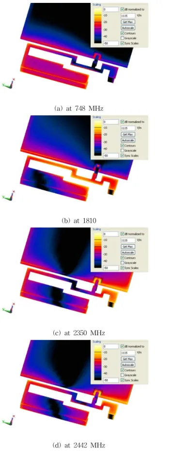
Fig. 2 shows the surface current distribution in the
(a) at 748 MHz
(b) at 1810
(c) at 2350 MHz
(d) at 2442 MHz
(e) at 2495 MHz
(f) at 2595 MHz
Fig. 2. Current distribution of the proposed antenna.
from the SEMCAD X simulation at 748 MHz, 1810 MHz, 2350 MHz, 2442 MHz, 2495 MHz, and 2595 MHz.
The proposed antenna has two branch lines. The long branch is the major radiation element for the proposed antenna at 748 MHz. On the left side, a short branch plays a major role for 2442 MHz, 2495 MHz and 2595 MHz.
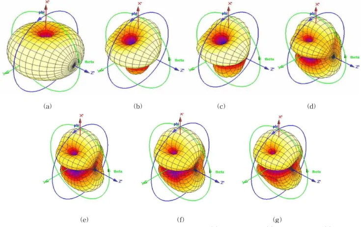
Fig. 3. shows simulated 3D radiation patterns at 748 MHz, 1810 MHz, 1920 MHz, 2350 MHz, 2442 MHz, 2495 MHz, 2595 MHz.
Fig. 4. shows the measurement and simulation results on the S11 of the proposed antenna. The results show a strong agreement between measurement and simulation. The implemented antenna satisfied multiple operation bands including LTE 700/2300/2500, K-PCS, US-PCS, Wibro, Bluetooth, and US-WiMAX bands.
(a) (b) (c) (d)
(e) (f) (g)
Fig. 3. Simulated 3D radiation patterns for the proposed antenna. (a) at 748 MHz, (b) at 1810 MHz, (c) at 1920 MHz, (d) at 2350 MHz, (e) at 2442 MHz, (f) at 2495 MHz, (g) at 2595 MHz.
Fig. 4. Simulated and measured S11 & S22 Fig. 5. Simulated and measured S12
y-z plane x-y plane
z-x plane (a) at 748 MHz
y-z plane x-y plane
z-x plane (b) 1810 MHz
y-z plane x-y plane
z-x plane (c) 1920 MHz
y-z plane x-y plane
z-x plane (d) 2345 MHz
y-z plane x-y plane
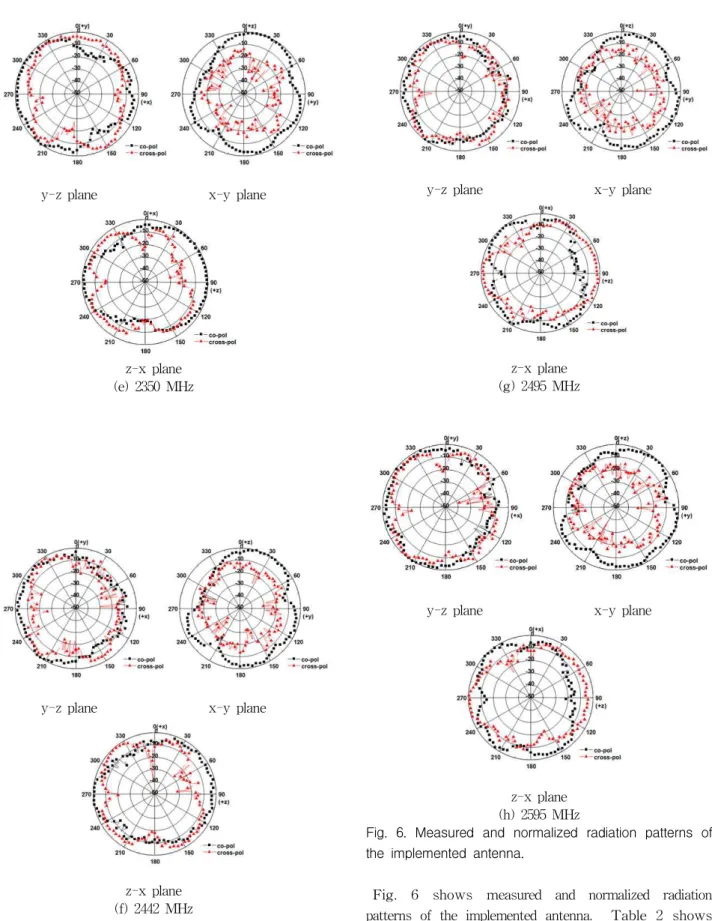
z-x plane (e) 2350 MHz
y-z plane x-y plane
z-x plane (f) 2442 MHz
y-z plane x-y plane
z-x plane (g) 2495 MHz
y-z plane x-y plane
z-x plane (h) 2595 MHz
Fig. 6. Measured and normalized radiation patterns of the implemented antenna.
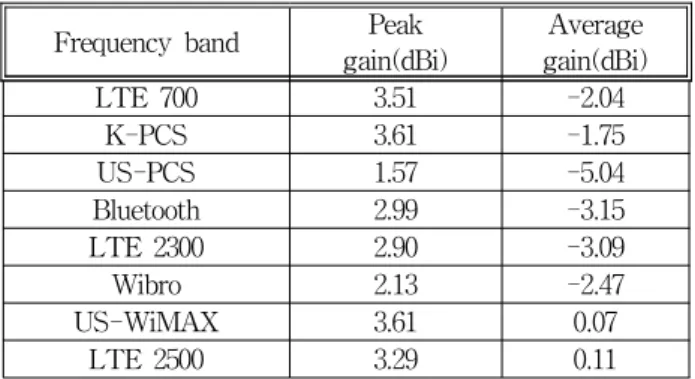
Fig. 6 shows measured and normalized radiation patterns of the implemented antenna. Table 2 shows the measured results on peak gain and the average gain of the implemented antenna. On each band, the
antenna. The average gain is the averaged value of the measured gain for each frequency band measurement. As shown in Table 2, a good gain characteristic is obtained for 748MHz and omni-directional radiation pattern is obtained for co-pol radiation pattern as shown in Fig. 6 (a) which is a desired pattern for a mobile handset.
Table 2. Measured antenna gains.
Frequency band Peak
gain(dBi) Average gain(dBi)
LTE 700 3.51 -2.04
K-PCS 3.61 -1.75
US-PCS 1.57 -5.04
Bluetooth 2.99 -3.15
LTE 2300 2.90 -3.09
Wibro 2.13 -2.47
US-WiMAX 3.61 0.07
LTE 2500 3.29 0.11
Through this table we can see that the maximum peak gain and average gain of the LTE 700 band are 3.51dBi, -2.04dBi, respectively. For the K-PCS band, the maximum peak gain and average gain are 3.61dBi, -1.75dBi, respectively. For the US-PCS band, the maximum peak gain and average gain are 1.57dBi, -5.04dBi, respectively. For the Bluetooth band, the maximum peak gain and average gain are 2.99dBi, -3.15dBi, respectively. For the LTE 2300 band, the maximum peak gain and average gain are 2.90dBi, -3.09dBi, respectively. For the Wibro band, the maximum peak gain and average gain are 2.13dBi and -2.47dBi, For the US-WiMAX band, the maximum peak gain and average gain are 3.61dBi and 0.07dBi, For the LTE 2500 band, the maximum peak gain and average gain are 3.29dBi, and 0.11dBi, respectively.
Compared to ref. [6], an implemented antenna shows a little bit higher antenna gain.
Couplings between the antennas and currents on the ground surface make it difficult to get high isolation between antennas. These mutual interferences increase an envelope correlation between antennas and also decrease radiation efficiency.
To minimize a coupling between two antennas, antenna distance should be more than a half wavelength of the operation frequency. But in this case, it is difficult to apply to commercializing devices because of the limited volume of the mobile devices. Measured and simulated S12 at 750MHz of the proposed antenna is -9.33 dBi, –3.27 dBi, respectively. For the stable 4G communication system, MIMO antenna with high isolation is required. Consequently, improvement on isolation of the MIMO antenna will be studied.
Ⅳ. Conclusion
A MIMO antenna suitable for LTE 700/2300/2500, PCS, Wibro, Bluetooth, Wimax has been proposed, implemented and evaluated. The proposed antenna has a small volume of 51×20×5mm3, and its ground size is 60×100mm2. The three desired operating frequency bands for covering the LTE 700, and K-PCS/US-PCS and LTE 2300/2500, Wibro, Bluetooth, US-WiMAX are implemented suitably.
Good radiation characteristics for frequencies over the three LTE bands have been observed.
We expect that the proposed MIMO antenna can be applicable for multi-band mobile handsets and tablet computers.
References
[1] Dong Ki Cho, Ho Cheol Son, and Jin Woo Lee, Sang Woon Lee, and Mun Soo Lee, “A study on the enhancement of isolation of the MIMO antenna for LTE/DCS1800/USPCS1900 handset”, Journal of IEEK, vol. 47, no. 10, Oct. 2010.
[2] Wei-Yu Li and Kin-Lu Wong, “Seven-band surface-mount loop antenna with a capacitively coupled feed for mobile phone application,” Microwave and Optical Technology Letter, vol. 51, no. 1, pp.
81-88, Jan. 2009.
[3] Kin-Lu Wong, Chao-An Lyu, and Liang-Che Chou, “Small-size multiband planar antenna for LTE700/ 2300/2500 operation in the tablet computer”, Microwave and Optical Technology Letter, vol. 54, no.
1, pp. 81-86, Jan. 2012.
[4] Ki Suk Yoon, Su Bin Park, Sung Min Kim, and Woon Geun Yang, “Penta-band internal antenna for
Woon Geun Yang (Member)
1983 : BS degree in Electronics Engineering, Seoul National University.
1985 : MS degree in Electronics Engineering, Seoul National University.
1994 : PhD in Electronics Engineering, Seoul National University.
1988~ : Faculty of Dept. of Electronics Engineering, University of Incheon.
1997~2001 : Consulting Professor, LG Electronics Inc.
2001~2002 : Invited Researcher, ETRI
(Electronics and Telecommunications Research Institute)
2004~2005 : Consulting Professor, LG Electronics Inc.
1985 : MS degree in Electronics Engineering, Seoul National University.
1989 : PhD in Electronics Engineering, Seoul National University.
1992~ : Faculty of Dept. of Electronics Engineering, University of Incheon.
Seong Ha Lee (Member)
2011 : BS degree in Electronics Engineering, University of Incheon.
2011~ : MS course in Electronics Engineering, University of Incheon.
no. 8, Aug. 2006.
[7] Xing Zhao, Youngki Lee, and Jaehoon Choi,
“Design of printed MIMO antenna with metamaterial matching network for LTE mobile handset application”, ISAP 2011, Oct. 2011.
[8] Minseok Han and Jaehoon Choi, “Dual-band MIMO antenna using polarization diversity for 4G mobile handset application”, Microwave and Optical Technology Letter, vol. 53, no. 9, pp. 2075-2079, Sep.
2011.
[9] Woon Geun Yang, Ling Zhi Cai, and Cheol Yong Yang, “Design and implementation of internal multi-band monopole antenna for mobile phones”, Journal of IKEEE, vol. 15, no. 4, Dec. 2011.
[10] Hongpyo Bae, Frances J. Harackiewicz, Myun-Joo Park, Taekyun Kim, Namhoon Kim, Deokyun Kim, and Byungje Lee, “Compact mobile handset MIMO antenna for LTE700 applications”, Microwave and Optical Technology Letter, vol. 52, no.
11, pp. 4219-2422, Nov. 2010.