Pseudo-Orthogonal Space-Time Block Codes for MIMO-OFDM Systems over
Frequency-Selective Channels
Heunchul Lee, Seokhwan Park and Inkyu Lee
School of Electrical Engineering Korea University, Seoul, Korea
Abstract
This paper proposes a new class of Space-Time Block Codes, which is manipulated from the existing transmit diversity schemes.
We analyze the performance and the receiver complexity of the proposed scheme and confirm that the new diversity scheme can yield performance gain over other existing four-transmit antenna cases. By relaxing the diversity criterion on code designs, the proposed space-time code provides a full transmission rate for four-transmit antennas and makes it possible to approach the open-loop Shannon channel capacity. Outage capacity and simulation results are used to show that substantial improvements in performance while maintaining a simple linear processing receiver structure are obtained in frequency selective channels
1. Introduction
Recently, many researchers have studies using multiple antennas with space-time codes (STC) since a simple transmit diversity concept was introduced by Alamouti [1]. The STC techniques are used to improve the performance of multiple-input multiple-output (MIMO) systems. The potential gains of the STC/MIMO system are presented in [2,3,4,5,6,7,8,9]. A core idea is the space-time signal processing in which the time domain operation is complemented with the spatial dimension processing inherent in the use of spatially distributed multiple antennas. Mostly, space-time coding schemes have been developed assuming flat fading channels. As the increasing demand for higher bit rates leads to wideband communications, the wireless channels become frequency selective. It has been presented in [10] [11] that multicarrier modulation realized by orthogonal
This work was supported by the Ministry of Information and Communication (MIC), Korea, under the Information Technology Research Center (ITRC) support program, supervised by the Institute of Information Technology Assessment (IITA).
frequency division multiplexing (OFDM) is well suited for
such broadband applications. The OFDM modulation technique divides the total available bandwidth into a number of equally spaced frequency bands. By applying a proper cyclic prefix, the individual subchannels can be considered to show flat fading channel characteristics. Furthermore, OFDM can exploit frequency diversity by applying channel coding.∗
The construction of space-time coding schemes is to a large extent a trade-off among the following three goals:
maximizing the error performance (i.e., diversity order and coding gain), maximizing the code rate and maintaining a simple decoding [5] [12]. For flat fading channels, optimizing the diversity order is the most critical point in designing STC.
In contrast, for frequency selective channels where frequency diversity is available, the full diversity becomes a less important issue. Therefore, a better strategy is to loosen the full diversity condition and complement the loss of the diversity order by the channel frequency diversity exploited by OFDM-based systems so that we can concentrate on the full rate and maximize the coding gain instead. In this paper, we propose pseudo-orthogonal space-time block codes for MIMO-OFDM systems over frequency-selective channels. It will be shown that the proposed pseudo-orthogonal scheme provide additional coding advantage while maintaining a simple decoding algorithm.
The organization of the paper is as follows. In section II, we
construct a new class of space-time block codes (STBC) and derive a receiver algorithm. In section III, we analyze the performance of the new scheme. In section IV, we compute the outage capacity of the proposed STBC and compare it to other alternative schemes. In section V, the simulation results are presented comparing to other competing designs. Finally, the paper is terminated with conclusions in section VI.
2. A New Class of Space-Time Block Code
In this section, we introduce a new class of space time block code. We relax the definition of complex orthogonal designs in [2] to obtain the full rate STBC. Here we define a pseudo-orthogonal matrix as follows.
Definition 1. A pseudo-orthogonal1 (PO) design in variables
1
,
2, ,
nx x K x
*
is an n by n matrix
C
such that● The entries of
C
are* *
1
,
1,
2,
2, , ,
nx x x x x x
± ± ± ± K ±
n±
● , where is a diagonal matrix with
th
H
=
C C D D
( ) i i ,
diagonal element of the form
( l x1i 12+ l x
2i 22+ + K l x
ni n 2)
,
with non-negative coefficients
l l
1i, ,
2iK , l
ni such that1 2
i i i
l + + + = l K l
nn
where
H
and denote the complex-conjugate and transpose and the complex conjugate respectively. In contrast to the definition of orthogonal designs in [2], the pseudo-orthogonal schemes allow zero coefficients*
i
l
j such thatD
is no longer an identity matrix.For simplicity, we focus on the four transmit antenna case in this paper. The CDMA transmit diversity method introduced in [13] satisfies the pseudo-orthogonal code design conditions. We start from the Alamouti scheme [1] as a base matrix to build higher order matrices. Let us first define the code matrix
X
ij asij i* *j
j i
x x
x x
⎡ ⎤
= ⎢− ⎣ ⎦
X ⎥
. (1)
Then,
X
ij is a well known Alamouti code matrix. We1 Quasi-orthogonal and Semi-orthogonal are already defined for different class.
extract some properties from the Alamouti matrix (1) and 2x2 Hadamard matrix in [14].
Then, the transmission matrix is given as
1 2 3 4
* * * *
12 34 2 1 4 3
12 34 1 2 3 4
* * * *
2 1 4 3
x x x x
x x x x
x x x x
x x x x
⎡ ⎤
⎢ − − ⎥
⎡ ⎤ ⎢ ⎥
= ⎢ ⎣ − ⎥ ⎢ ⎦ = ⎢ − − ⎥ ⎥
− −
⎢ ⎥
⎣ ⎦
X X
C X X
.(2)
The code matrix (2) satisfies the pseudo-orthogonal code design conditions such that
1
† 1
2
2
0 0 0
0 0
0 0 0
0 0 0
d d
d d
0
⎡ ⎤
⎢ ⎥
⎢ ⎥
= ⎢ ⎥
⎢ ⎥
⎢ ⎥
⎣ ⎦
C C
where
d
1= 2 ( x
12+ x
2 2)
and(
2)
2
2
3 4d = x + x
2 . It is straightforward to check that the minimum rank of the matrix( x
c1− x x
e1,
c2− x
e2, x
c3− x x
e3,
c4− x
e4)
C
as in [3] istwo. For simplicity, we assume the single receive antenna case.
Let us define the received signal vector , the code matrix , and the noise vector
n
Then the received signals can be written asr
C
.
1 1
2 2
3 3
4 4
r h
r h
r h
r h
⎡ ⎤ ⎡ ⎤
⎢ ⎥ ⎢ ⎥
⎢ ⎥ ⎢ ⎥
= = +
⎢ ⎥ ⎢ ⎥
⎢ ⎥ ⎢ ⎥
⎢ ⎥ ⎢ ⎥
⎣ ⎦ ⎣ ⎦
r C n
(3)where we assume that is a vector of additive noise terms, which are independent and identically-distributed complex Gaussian with variance
n
2
1
σ
n=
. The channel coefficient is the path gain from the transmit antennai
to the receive antenna. The path gains are modeled as samples of independent complex Gaussian random variables with variance 0.5 per dimension. This choice models a Rayleigh fading environment.h
iBy taking the complex-conjugate operation on the second and the fourth element of
r
in (3), we obtain
r % = Hx n + %
(4)where 1 2* 3 *4 ,
n n n n
T⎡ ⎤
= ⎣ ⎦
n %
[
1 2 3 4]
x x x x
T=
x
and* *
1 2 3 4
r r r r
T= ⎣ ⎡
r % ⎤⎦
⎤ ⎥
⎥ ⎥
⎥ ⎥⎦
0
. Here is a channel matrix with space (in columns) and time (in rows) dimensions defined as
H
1 2 3 4
* * * *
2 1 4 3
1 2 3 4
* * * *
2 1 4 3
h h h h
h h h h
h h h h
h h h h
⎡ ⎢ − −
= ⎢
⎢− −
⎢ − −
⎢⎣
H
.This channel matrix inherently possesses a pseudo-orthogonal property such that
1
1
2
2
0 0 0
0 0
0 0 0
0 0 0
H
γ γ
γ γ
⎡ ⎤
⎢ ⎥
⎢ ⎥
= ⎢ ⎥
⎢ ⎥
⎢ ⎥
⎣ ⎦
H H
(5)where
γ
1= 2 h ( 12+ h
22)
and γ
2 = 2 h ( 32+ h
42)
.
+ h
42)
.We are now ready to begin linear processing at the receiver using the vector channel model in (4). We will assume that the realization of is known to the receiver, but not to the transmitter. The MIMO channel can be decomposed into parallel channels by applying the channel matched filter
H
H
H, his results inand t
r ) = H r
H% = Dx n + )
(6) whereD
is a diagonal matrixD = diag ( γ γ γ γ
1,
1,
2,
2)
and
=
Hn ) H n %
.The estimated signal
x )
can then be obtained as1 1
− −
= = +
x ) D r ) x D n )
.Computing the noise autocorrelation matrix yields
(
1)(
1)
1 1
1
.
H nn
H H
E E
− −
− −
−
⎡ ⎤
= ⎢ ⎣ ⎥ ⎦
⎡ ⎤
= ⎣ ⎦
=
R D n D n
D H nn HD D
) )
% %
The diversity gains corresponding to recovering
( , x x
1 2)
and
( , x x
3 4)
areγ
1 andγ
2, respectively. Thus the diversity gain reduces from( h12+ h
22+ h
32+ h
42)
to
2 h ( 12+ h
22)
or 2 h ( 32+ h
4 2)
compared to the
full diversity scheme. Note that the proposed scheme achieves
the full rate at the expense of the reduced transmit diversity.
+ h
4 2)
compared to the full diversity scheme. Note that the proposed scheme achieves the full rate at the expense of the reduced transmit diversity.We will later observe that in spite of the partial transmit diversity, the proposed scheme outperforms the full diversity designs for frequency selective channels.
It has been shown [2] that transmission using orthogonal designs provides a full diversity and a simplified decoding algorithm and also that for more than two transmit antennas there exists no complex orthogonal code which achieves the full diversity and the full rate at the same time. Therefore, for a system employing more than two transmit antennas, either the diversity order or the transmission rate should be sacrificed. In order to achieve the full rate, the proposed pseudo-orthogonal codes do not fully satisfy the complex orthogonal code design conditions in [2]. Nonetheless, we maintain an orthogonality property so that the proposed code can still employ a very simple maximum-likelihood decoding algorithm at the cost of the partial diversity order.
Suppose a set consisting of all possible symbol vectors . Then the size of is equal to
S
x S M
4, whereM
represents the number of constellation points. The ML detection for the transmitted symbol vector in (4) can be obtained as
arg min
2∈S
= −
x
x
)r Hx
) % )
. (7) Using the fact that is pseudo-orthogonal as shown in (5), the ML solution yieldsH
( ) ( )
( ) ( ) ( )
( )
22
arg min arg min arg min
arg min .
H S
H H
S H S
H S
∈
∈
∈
∈
= − −
= − −
= −
= −
x
x
x
x
x r Hx r Hx
r Hx H H r Hx H r Hx
H r Dx
) )
)
)
) % ) % )
) )
% %
% )
% )
(8)
Thus the ML decoding rule in (7) is reduced to a simple decorrelating expression in (8).
Let us define as the
i
th column vector in . Then the decision metric for detectingh
iH
x
1 orx
2 is obtained from (8) as2 1 H i
− γ x
ih r %
,And similarly the metric for detecting
x
3 orx
4 is2 2 H
j
− γ x
jh r %
.It is also straightforward to see that the decision rule can be extended to multiple receive antenna. The decoding scheme for the pseudo-orthogonal design is as simple as the one established for the complex orthogonal designs in [2]. Also soft output for the transmitted symbol is readily available.
These soft decisions are fed to the outer channel code (e.g., convolutional codes) to yield better performance.
3. Code Design Criteria
We analyze the proposed STBC in terms of the performance criteria presented in [3]. The design criteria for space-time codes are fully formulated through the codeword difference matrix , which is defined as
. Here is the transmitted code matrix and is the erroneously detected matrix. The probability of transmitting the codeword
B
cece
=
c−
eB C C C
cC
e( c
1(1), , ( ), c l
1=
c K K
)
, c l
n( ), K , (1) c
l and deciding erroneously in favor of adifferent codeword is given by [3]
( e
1(1), , e
n(1), , ( ), e l
1, e l ( ) )
=
e K K K
n( )
( )
21 1 1
, 1, 2, , , 1, 2, ,
exp ( ) ( )
4
ij
m l n
s
ij i i
j k i
o
P h i n j m
E h c k e k
N
= = =→ = =
⎛ ⎛ ⎞ ⎞
≤ ⎜ ⎜ ⎝ − ⎜ ⎝ ⎟ ⎠ ∑∑ ∑ − ⎟ ⎟ ⎠
c e K K
where , and
l
represent the number of transmitters, receivers, and the packet, respectively. Under the assumption of Rayleigh fading channels, the above error probability bound can be rewritten after some algebra asn m
( )
1
4
m rm r
i s
i o
P E
λ N
− −
=
⎛ ⎞
⎛ ⎞
→ ≤ ⎜ ⎟ ⎜ ⎟
⎝ ∏ ⎠ ⎝ ⎠
c e
(9)where
r
denotes the rank of matrixA = B B
†ce ce andλ
i denotes nonzero eigenvalues of . Thus a diversity advantage of and a coding advantage ofare achieved. Since the matrix has an equivalent property with the matrix in the sense of rank and determinant, we proceed to investigate the matrix
to minimize the pairwise error probability (PEP), which determines the performance at high signal-to-noise ratios.
A rm
(
1 2 1/r
λ λ K λ
r) B
ceA
B
ceConcentrating on the four transmit antenna systems, we compare with other complex orthogonal designs. Let us define
P
and as the pseudo-orthogonal designs and the orthogonal designs, respectively. Then the diversity order isO
2 2 2
1
4 2
3 2
min rank min rank 2 0
0 0
0 0
2 2
0
H
ce ce ck ek
c e c e
k
ck ek
k
P P x x
x x
≠ ≠ =
=
⎡ ⎡ ⎤
⎡ ⎤ = ⎢ − ⎢ ⎥
⎣ ⎦ ⎣ ⎣ ⎦
⎡ ⎤ ⎤
+ − ⎢ ⎥ ⎥ =
⎣ ⎦⎦
∑
∑
I
I .
It is now clear that the diversity of the pseudo-orthogonal designs is 2 while the diversity of orthogonal designs is 4.
We recognize here that the multiplicative term 2 in diagonal terms makes a coding advantage in terms of the determinant criteria for the pseudo-orthogonal codes. The evaluations of the determinant criteria for
P
andO
then yield4 4
2
1 8
min det min
for 1, , 4
H
ce ce ck ek
c e c e
k
ck ek
O O x x
x x k
≠ ≠ =
⎡ ⎤
⎡ ⎤ = ⎢ − ⎥
⎣ ⎦ ⎣ ⎦
= − =
∑
K
and
2 2
2
1 4 2
2
3 4
min det min 4
4 for
H
ce ce ck ek
c e c e k
ck ek
k
ck ek
P P x x
x x
x x k
≠ ≠ =
=
⎡ ⎤
⎡ ⎤ = ⎢ − ⎥
⎣ ⎦ ⎣ ⎦
⎡ ⎤
⊗ ⎢ ⎣ − ⎥ ⎦
= − =
∑
∑
K 1, , 4
where
⊗
denotes product between nonzero values and leave out the zero values.The minimum value of
( det ⎡ ⎣ C C
Hce ce⎤ ⎦ )
1/r determines the coding advantage in (9). Therefore, the coding gain of the orthogonal designO
isx
ck− x
ek2 whereas the coding gain of the pseudo-orthogonal designP
is2 x
ck− x
ek 2. Consequently, the pseudo-orthogonal designs have a 3dB coding gain over the orthogonal design.4. Channel Capacity
In this section, we analyze the channel capacity for the proposed scheme and compare with other alternatives. We require that the total transmitted power is held constant independently of the number of transmit antennas.
Components of are assumed to be independent and identically distributed. Then we have
x
H
E
NN
⎡ ⎤ = ρ
⎣ xx ⎦ I
where
ρ
is the SNR at the receiver and denotes the identity matrix of order .I
NN
The capacity of systems with transmit antennas is given by [4]
N
2 2
1
log 1 b/s/Hz.
N
N i
i
C h
N ρ
=
⎛ ⎞
= ⎜ + ⎟
⎝ ∑ ⎠
(10)
Note that the capacity
C
N approaches the Gaussian capacitylog (1
2+ ρ )
as becomes larger [15]. In practice, the random variableN
2 1
1
Ni
h
iN ∑
= is already close to 1 when is as small as 4 [3]. This motivates us to explore a compromise between the full rate and full diversity.N
The Alamouti scheme [1] achieves the open-loop capacity of (10) with
N = 2
−100 −5 0 5 10 15 20
1 2 3 4 5 6
ρ[dB]
bps/Hz
4x1 open−loop capacity 4x1 pseudo−orthogonal 4x1 quasi−orthogonal 2x1 Alamouti 4x1 rate 3/4 orthogonal
Figure 1. Outage capacities compared to other alternative schemes
(
12 22)
log
21
Al
2
h h
C ⎛ ρ +
⎜ ⎟
= ⎜ ⎜ ⎝ + ⎟ ⎟ ⎠
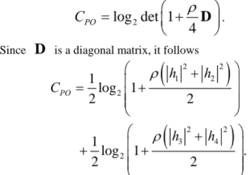
We can calculate the channel capacity of the pseudo-orthogonal scheme using the vector channel model (6).
The capacity is then given by
log det 1
2 PO4
C = ⎛ ⎜ + ρ ⎞ ⎟
⎝ D ⎠
. SinceD
is a diagonal matrix, it follows( )
( )
2 2
1 2
2
2 2
3 4
2
1 log 1
2 2
1 log 1 .
2 2
PO
h h
C
h h
ρ
ρ
⎛ + ⎞
⎜ ⎟
= ⎜ ⎜ ⎝ + ⎟ ⎟ ⎠
⎛ + ⎞
⎜ ⎟
+ ⎜ ⎜ ⎝ + ⎟ ⎟ ⎠
We now investigate the outage capacity to illustrate the impact on the systems. The
ε
outage capacity is defined as [15]b
( ) : max such that (
C
εoutb b b P b
⎞
.
) ε
= ⎡ ⎣ ≤ ⎤ ⎦
where
P b ( )
denotes the probability that the data rate can not be supported. The outage capacity is calculated by Monte-Carlo simulations and provides additional insight into the performance characteristics of different designs [17]. The 10% outage capacities of the different schemes are plotted in Figure 1. The channel capacities for the quasi-orthogonal codes and orthogonal codes are obtained from [17]. For comparison purposes, this figure includes the system with two transmit antennas and one receive antenna as a reference. No other alternatives outperform the pseudo-orthogonal design except for 4x1 open-loop capacity, which is merely a theoretical case. We emphasize that the pseudo-orthogonal design employs much simpler decoding algorithm than any other alternatives for four transmit antennas.b
5. Simulation Results
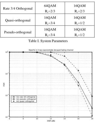
In this section, we present the simulation results for the four-transmit antenna systems. The system parameters are summarized in Table I. The binary convolutional code polynomials
(133, 171) in octal notation are used throughout the simulation.
3bps/Hz 2bps/Hz
Rate 3/4 Orthogonal 64QAM Rc=2/3
16QAM Rc=2/3 Quasi-orthogonal 16QAM
Rc=3/4
16QAM Rc=1/2 Pseudo-orthogonal 16QAM
Rc=3/4
16QAM Rc=1/2 Table I. System Parameters
6 8 10 12 14 16 18
10−3 10−2 10−1 100
SNR (dB)
FER
3bps/Hz in 5 tap exponentially decayed fading channel
4x1 rate 3/4 orthogonal 4x1 pseudo−orthogonal 4x1 quasi−orthogonal
Figure 2. Performance comparison to other alternative schemes
4 5 6 7 8 9 10 11 12 13
10−3 10−2 10−1 100
SNR (dB)
FER
2bps/Hz in 5 tap exponentially decayed fading channel
4x1 rate 3/4 orthogonal 4x1 pseudo−orthogonal 4x1 quasi−orthogonal
Figure 3. Performance comparison to other alternative schemes
The spectral efficiencies of 2bps/Hz and 3bps/Hz are assumed.
We use a typical indoor channel model with a 5 tap power delay profile having exponentially decayed fading
characteristics where each ray is assumed to be independently Rayleigh fading. The OFDM modulation defined in the 802.11a standard with 64 point FFT are used. One OFDM symbol duration is 4
μ s
including the 0.8μ s
guard interval. This specification is designed to handle the root mean square (RMS) delay spread up to 250ns. The 5 tap multipath channel used in the simulations accounts for approximately the RMS spread of 100 ns. The length of the frame is assumed to consist of four OFDM symbol. It has been shown [18] that a rotation of constellation results in a performance improvement for the quasi-orthogonal codes. A optimal rotation of constellation obtained in [18] is used for the quasi-orthogonal codes. For the rate 3/4 orthogonal codes, we have used the code matrix in [19].First, Figure 2 shows the comparison between different schemes with 3 bps/Hz in a 4 by 1 system. It is observed from the plot that the proposed scheme exhibits about a 1dB gain over the orthogonal designs and performs as good as quasi-orthogonal codes at 1% FER. Considering the receiver complexities, the pseudo-orthogonal codes with a simple decoding algorithm are much more attractive than the quasi-orthogonal codes which require the more complex decoder structure. It is also interesting that there is no distinctive slope change among different schemes in Figure 2.
This is due to the fact that the frequency selective channel contains some level of
frequency diversity inherent in the channel with OFDM.
The performance of OFDM-based systems can be further improved by applying lower rate channel coding exploiting additional frequency diversity. The frequency selective channels have more dramatic effect on the performance of pseudo-orthogonal codes. The frequency diversity can complement the partial transmit diversity of the pseudo-orthogonal codes. Figure 3 shows that the performance gain of the pseudo-orthogonal codes over the other schemes increases as lower channel coding rate is adopted.
The simulation results justify our code design that we can benefit from a reasonable compromise between a full rate and a full diversity. They also confirm that the coding gain shown in section III enhances the performance in the frequency selective channels, where a coding gain plays more important role than a diversity gain. Consequently, the simulation results show that a better performance is possible when more frequency diversity exists in the channel.
6. Conclusion
In this paper, a new class of space-time block codes has been presented and evaluated for frequency selective channels.
We have shown that the proposed scheme has a simple decoding structure and outperforms the existing other orthogonal designs for four transmit antenna systems.
Furthermore, the computer simulation demonstrates that we need to consider the channel characteristics and take a compromise between the full rate and the full diversity. We have used the design criteria to justify the improvement of the performance for the pseudo-orthogonal. The proposed scheme can be generalized to the systems with larger number of transmit antennas.
References
[1] S. M. Alouini, “A simple transmitter diversity scheme for wireless communications,” IEEE Journal on Selected Areas in Communications, pp. 1451-1458, October 1998.
[2] V. Tarokh, H. Jafarkhani, and A. R. Calderbank,
“Space-time block codes from orthogonal designs,”
IEEE Transactions on Information Theory, vol. 45, pp.
1456-1467, July 1999.
[3] V. Tarokh, N. Seshadri, and A. R. Calderbank,
“Space-time codes for high data rate wireless communication: performance criterion and code construction,” IEEE Transactions on Information Theory, vol. IT-44, pp. 744–765, March 1998.
[4] I. E. Telatar, “Capacity of multi-antenna Gaussian channels,” Eur. Trans. Telecom., vol. 10, pp. 585–595, November 1999.
[5] A. Naguib and et al, “From Theory to Practice:An Overview of MIMO Space-Time Coded Wireless Systems,” IEEE Journal on Selected Areas in Communications, vol. 21, pp. 281–302, April 2003.
[6] G. J. Foschini, “Layered space-time architecture for wireless communication in a fading environment when using multi-element antennas,” Bell Labs. Tech. J., vol.
1, pp. 41–59, 1996.
[7] G. J. Foschini and M. Gans, “On limits of wireless communications in a fading environment when using multiple antennas,” Wireless Pers. Commun., vol. 6, pp.
311–335, Mar. 1998.
[8] S. H. Muller-Weinfurtner, “Coding Approaches for Multiple Antenna Transmission in Fast Fading and OFDM,” IEEE Trans. on Signal Processing, vol. 50, pp.
2442–2450, October 2002.
[9] E. Biglieri, G. Caire, and G. Taricco, “Recent Results on Coding for Multiple-Antenna Transmission Systems,” in 6th Int. Symp. on Spread-Spectrum Tech. & Appl., pp.
117–121, 2000.
[10] L. J. Cimini, “Analysis and simulation of a digital mobil channel using orthogonal frquency division multiplexing,” IEEE Transactions on Communications, vol. 33, pp. 665–675, July 1985.
[11] J. A. Bingham, “Multicarrier modulation for data transmission: An idea whose time has come,” IEEE Commun. Mag., pp. 5–14, May 1990.
[12] E. G. Larsson and P. Stoica, Space-Time Block Coding for Wireless Communicaions. The Edinburgh Building, Cambridge, UK: Cambridge University Press, 2003.
[13] L. M. Jalloul, K. Rohani, K. Kuchi, and J. Chen,
“Performance analysis of CDMA transmit diversity methods,” Vehicular Technology Conference, vol. 3, pp.
1326 – 1330, Sept. 1999.
[14] A. V. Geramita and J. Seberry, “Orthogonal Designs, Quadratic Forms and Hadamard Matrices,” Lecture Notes in Pure and Applied Mathematics, vol. 43, 1979.
[15] G. J. Foschini and M. Gans, “On Limits of Wireless Communications in a Fading Environment when Using Multiple Antennas,” Wireless Personal Communications, vol. 6, pp. 311–335, March 1998.
[16] B. Lu, X. Wang, and K. R. Narayanan, “LDPC-Based Space-Time Coded OFDM Systems Over Correlated Fading Channels: Performance Analysis and Receiver Design,” IEEE Transactions on Communications, vol.
50, pp. 74–89, January 2002.
[17] C. B. Papadias and G. J. Foschini,
[18] “Capacity-Approaching Space-Time Codes for Systems Employing Four Transmitter Antennas,” IEEE Trans. on Information theory, vol. 49, pp. 726–733, March 2003.
[19] N. Sharma and C. Papadias, “Improved quasi-orthogonal codes through constellation rotation,” IEEE Transactions on Communications, vol. 51, pp. 332–335, march 2003.
[20] O. Tirkkonen and A. Hottinen, “Square-Matrix Embeddable Space-Time Block Codes for Complex Signal Constellations,” IEEE Transactions on Information Theory, vol. 48, pp. 384–394, February 2002.
저 자 소 개
이 흔 철 (Heunchul Lee)
2003 년 2 월 고려대학교 전기공학과 졸업 2005 년 2 월 고려대학교 전파공학과 석사
2008 년 2 월 고려대학교 전자전기공학과 박사 2008 년 3 월~현재 : 동대학원 박사후 과정
<관심분야> Space-Time coding, signal processing and coding for wireless communications.
박 석 환 (Seokhwan Park)
2005 년 2 월 고려대학교 전기전자전파공학부 졸업 2007 년 2 월 고려대학교 전파공학과 석사
2007 년 3 월~현재 고려대학교 전자전기공학과 박사과정
<관심분야> Downlink Beamforming and Detection Techniques for
Multi-Antenna and Multi-User Systems
이 인 규 (Inkyu Lee) 1990 년 2 월 서울대학교
제어계측공학과 졸업
1992 년 2 월 스탠포드대학교 전자공학과 석사
1995 년 2 월 스탠포드대학교 전자공학과 박사
2002 년 9 월~현재 고려대학교
전기전자
전파공학부 부교수
<관심분야>Digital Communications, signal processing, and coding techniques applied to wireless communications.