하중 위치에 따른 시멘트 유지형 임플란트 지지골의 유한요소법 응력 분석
김 갑 진
부산가톨릭대학교 치기공학과Finite element analysis of stress distribution on supporting bone of cement retained implant by loading location
Kap-Jin Kim
Department of Dental Laboratory Science, Catholic University of Pusan
Purpose: The purpose of this study is to evaluate the effect of two different oblique mechanical loading to occlusal surfaces of cement retained implant on the stress distributions in surrounding bone, using 3-dimensional finite element method.
Methods: A 3-dimensional finite element model of a cement retained implant composed of three unit implants, simplified ceramic crown and supporting bone was developed according to the design of ement retained implant for this study. two kinds of surface distributed oblique loads(100 N) are applied to following occlusal surfaces in the single crowns; 1) oblique load on 2 occlusal points(50N for each buccal cusp, 2 buccal cusps exist), 2) oblique load on 4 occlusal points(25N for each buccal and lingual cusp, 2 buccal and 2 lingual cusps exist)
Results: The results of the comparison of the stress distributions on surrounding bone are as follows. In the condition of oblique load on 2 occlusal points, VMS was 741.3 Mpa in the M1( Ø 4.0×13㎜) model and 251.2 Mpa in the M2( Ø 5.0×13㎜) model. It means the stress on the supporting bone is decreased. The results of oblique load on 4 occlusal points are similar to this one.
Conclusion: Increasing the diameter of the implant fixture is helpful to distribute the stress on the supporting bone. Also, to obtain the structural stability of the supporting bone, it is effective to distribute the load evenly on the occlusal surface of crown in producing single crown implant.
[Abstract]
Key words :implant, finite element method, occlusal loading position, supporting bone
성 명 김 갑 진 전 화 051-510-0599 E-mail [email protected]
교신저자
Ⅰ. 서 론
치과 임플란트 보철물은 저작운동에 의한 반복하중을 받게 되므로 장기간의 안정성이 보장되어야 하며, 이를 위해서는 임플란트 자체의 구조적 안정성과 고정체와 지 지골간의 골유착과 같은 주위 골조직의 안정성 등이 유지 되어야 한다(Zhou 등, 2016).
주위 골조직의 안정성이 파괴되는 사항으로는 하중 조 기 부여, 지지조직 감염 등의 시술 실패와 과다한 외부 교 합하중으로 인한 고정체와 지지골 계면에서의 골유착 파 괴를 들 수 있다(Wang 등, 2016). 임플란트 상부구조물 에 가해지는 하중의 대부분을 상부 피질골이 지지한다고 알려져 있는데, 과도한 교합 응력은 골 흡수를 유발하고 이러한 흡수는 고정체와 골 접촉 계면과 주위 지지골 파 괴로 임플란트 시술 실패를 가져오게 된다(Himmlova 등, 2004). 그러므로 피질골 퇴행은 임플란트 시술 실패 를 초래하는 중요한 원인 중의 하나가 될 수 있으며, 임플 란트는 역학적으로 상부 피질골의 퇴행을 방지할 수 있는 응력 분포를 가지도록 고안되어져야 한다(Baggi 등, 2008).
임플란트에 가해지는 외부 하중은 대부분 저작운동에 의한 것이며 교합면을 통하여 전달된다. 임플란트 보철물 제작시 교합점 위치 설정은 고정체의 식립 위치와 방향, 교합관계, 인공치아 형태 등이 고려되어 결정된다. 교합 점 위치 선정은 외부 하중 위치가 치조골의 구조적 안정 성에 미칠 수 있는 생체역학적 영향을 고려하지 않을 경 우 고정체와 골의 유착 파괴를 발생시킬 수 있는 과하중 교합 응력 발생으로 작용하여 성공적인 임플란트 시술에 악영향을 미칠 수 있다(Eskitascioglu 등, 2004).
유한요소법을 이용한 연구는 실험에 영향을 줄 수 있는 많은 인자들에 대한 영향을 직접 시뮬레이션 함으로써 다 양한 인자들의 영향 정도를 미리 예측하여 실질적인 실험 기획을 용이하게 할 수 있으며, 시간과 경비를 절감할 수 있는 이점이 있다. 또한 발생되는 응력의 크기 및 분포를 전체적으로나 구성부분 개별적으로 파악할 수 있는 장점 이 있어 여러 재료로 구성된 구조물의 경우에 각 구조물
응력분포와 변화 양상, 변위량 등을 정성적으로 측정하는 데 있어 매우 효과적이다(Chang 등, 2010).
최근 유한요소법을 이용한 구조적으로 안정된 임플란트 디자인에 대한 연구와 다양한 매식체의 길이와 직경 등이 주변 골조직의 응력분포에 미치는 영향성 등에 관한 연구 와 저작운동 등의 외부하중 종류와 방향이 임플란트의 구 조 및 치조골의 안정성에 미치는 영향에 관한 연구 등이 활발하게 보고되고 있다(Ding 등, 2009; Sevimay 등, 2005).
그러나, 임플란트 관련 연구들은 생역학적 분석 방향이 임플란트 디자인과 표면 성질에 많이 편중되어 있으며 특 히, 상부 보철물 설계에 있어 간소화된 디자인을 사용하 고 있어 단관 임플란트 형태의 치과 보철물에서 하중 형 태나 위치에 따른 지지골의 구조적 안정성에 대한 연구는 상대적으로 부족하다.
따라서 본 연구에서는 기존 연구와 달리 상부 보철물을 범용성 프로그램을 사용하여 보다 정량적으로 설계하였 다. 그리고 단관 임플란트 상부 보철물의 하중 위치를 협 측교두 2개에 각각 50N 경사하중을 적용시켰을 때와 협 측과 설측 4개 교두에 각각 25N 경사하중을 적용했을 때 발생하는 지지골의 von Mises 응력값(이하 VMS)과 분포 양상을 고정체 직경을 달리하여 비교 분석하였다.
Ⅱ. 연구 방법
1. 3차원 실험 모델 설계
교합하중 적용에 따른 임플란트 고정체 지지골에서 발
생하는 응력 크기와 분포 양상을 파악하기 위한 3차원 유
한요소법 분석을 위해 제작한 구치부 단관 모델은 국내 D
사의 internal type 고정체와 시멘트 유지형 지대주와 지
대주나사를 선택하여 제조사 설계도면을 바탕으로 자료를
입력하였다. 임플란트 구조에 결합되는 상부 치관보철물
은 금속-도재관(metal-ceramic crown), 고정체 지지 치
조골 형태를 제작하여 이를 <Fig. 1>에 나타내었고 실험에
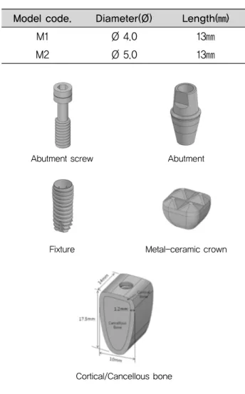
이용한 고정체 직경과 길이는 <Table 1>에 제시하였다.
고정체를 지지하는 치조골 형태는 협설폭 10㎜, 근원심 폭 14㎜, 높이 17.5㎜로 제작하고 1.2㎜ 두께 피질골 (cortical bone)과 잔존부위는 해면골(cancellous bone) 로 구성하였다.
상부 보철물 구조는 하악 제1 대구치를 가상한 형태로 모델링 하였다. 상부 치관보철물에 나사 구멍은 설계하지 않고 단순화하였다. 교합면은 근원심폭경 8㎜, 협설폭경 8㎜로 구성하였고 치아 교두 형태는 4교두 형태로 모델링 하였다. 금속-도재관 높이는 자연치를 모방한 8㎜로 하 였으며 2.5㎜ 지대주 구조를 포함한 지지골 상부 노출 구 조물의 총 높이는 10.5㎜로 하였다. 상부 보철물 구조는 시멘트 유지형으로 내부 지대주와 결합되는 금속 내관 (coping cap)과 치아형태를 모방한 도재관(ceramic crown)으로 구성하였으며, 보철물은 지대주에 치과용 시 멘트로 유지시키나 시멘트 층에 의한 영향성을 피하기 위
해 상부 보철물과 지대주는 완전 결합된 상태로 설정하였 다. 그리고 지대주와 고정체의 연결은 지대주나사 체결에 의한 결합으로 제조사 지시대로 20N㎝ 조임력 결합으로 제작하였고 각 구조가 결합된 모델을 <Fig. 2>에 나타내 었다.
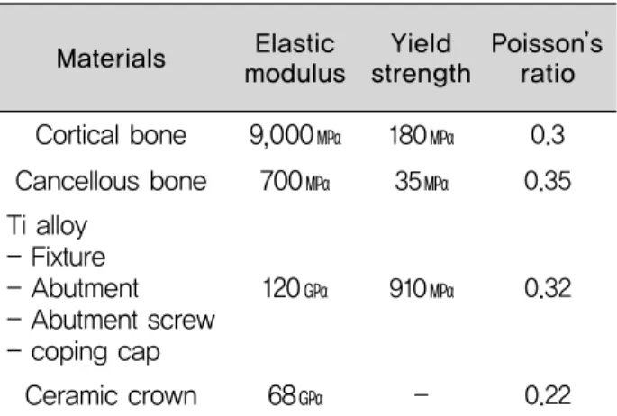
인체 피질골과 해면골은 이방성(anisotropy)이나 수치 적 계산에 의한 유한요소 분석을 위해 모델을 구성하는 전체 구조 부분은 등방성(isotropy)이고 균질성 (homogenization)이며 선형 탄성(linear elasticity)인 물질로 가정하였으며, 모델링과 유한요소 응력 분석은 유 한요소 해석 범용 프로그램인 Solidworks(Premium 2013, Dassault System., France)를 사용하였다.
모델을 구성하는 재료들의 탄성계수(Elastic modulus) 와 포와송비(Poisson’ s ratio)의 물성적 자료는 일반적인 역학실험의 공인 자료를 이용하였으며 <Table 2>에 나타 내었다.
Table 1. Characteristics of model code and fixture size Length(㎜) Diameter(Ø)
Model code.
M1 M2
Ø 4.0 Ø 5.0
13㎜
13㎜
Abutment screw Abutment
Fixture
Cortical/Cancellous bone
Metal-ceramic crown
Fig. 1. Schematic diagram of single implant dimensional data
Fig. 2. Schematic image of the loading conditions.
⒜: 2 point oblique loading 50N for each buccal cusp,
total 100N ⒝: 4 point oblique loading 25N for each
buccal and lingual cusp, total 100N
고정체 길이와 직경에 따른 3종의 모델링에 상용된 각 구성부분의 절점(node)과 요소(element) 수는 <Table 3>
에 제시하였다.
2. 하중 조건 및 구속 조건
본 연구에서의 하중 형태는 하중 위치에 따른 치조골의
VMS 분포를 분석하려는 목적에 충실하고자 협측교두 2 점과 협측교두와 설측교두를 포함하는 4점에 설측에서 협측으로 향하는 45° 경사하중을 적용하였으며 두 가지 하중조건은 각각 100N으로 하였다. 구속조건으로는 지지 골 최하단부위의 모든 절점을 6방향 자유도를 구속시켜 이 동 및 회전이 없도록 하였다. 교합점을 의미하는 하중 위치 는 교합면 중앙과 중앙으로부터 설측과 협측으로 2.8㎜ 이 동한 지점으로 2점과 4점을 지정하였다. 하중 조건에 대 한 그림은 <Fig. 2>에 나타내었다.
가해진 하중으로 인하여 발생하는 임플란트 주위 치조 골 조직의 구조적 안정성은 VMS값을 이용하여 분석하였 다. 각 모델과 하중 조건에 따른 최대 VMS 크기와 위치 를 분석하였으며 등간격으로 구분된 VMS 값 분포를 색 깔별로 나타내었다.
Ⅲ. 결 과
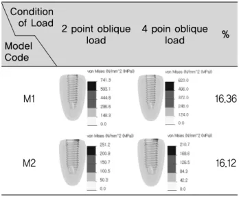
1. 하중 위치에 따른 지지골 VMS 응력 분석
2점 교합점 모델에 100N 경사하중을 적용하여 지지골 응력 분포를 비교한 결과 M1(Ø4.0×13㎜) 단관 모델에 서는 VMS 741.3㎫로 나타났으며, M2(Ø5.0×13㎜)는 251.2㎫로 지지골에 대한 응력이 감소한 것으로 나타났 다. 그리고 4점 경사하중 조건 모델의 경우 M1(Ø4.0×
13㎜)의 단관 모델에서는 VMS 620㎫로 나타났으며, M2(Ø5.0×13㎜)는 210.7㎫로 지지골에 대한 응력이 감 소하여 2 점 경사하중과 비슷한 경향성을 나타내었다. 또 한 모든 모델에서 지지골에서의 응력 양상은 고정체의 직 경에 관계없이 지지골 상부 즉 임플란트 고정체 상부와 골 접촉부 치밀골에서 응력이 집중되는 양상으로 나타났다.
2. 고정체 직경과 길이가 동일한 모델의 2 점 경사하 중과 4 점 경사하중의 VMS 분석
동일 조건 모델에서 2 점과 4 점 경사하중을 비교했을 때, M1 경우 2 점 경사하중에서 741.3 ㎫ 4 점 경사하중 620 ㎫을 나타냈다. 그리고 M2 는 2 점 경사하중에서 251 ㎫ 4 점 경사하중에서 210.7 ㎫을 나타냈다. 2 종의 모델은 각각 4 점 경사하중을 적용했을 때 2 점 경사하중 FEM model
Materials Elastic modulus
9,000㎫
700㎫
120㎬
68㎬
Yield strength
180
㎫35
㎫910
㎫-
Poisson’ s ratio
0.3 0.35
0.32
0.22
Cortical boneCancellous bone Ti alloy
- Fixture - Abutment - Abutment screw - coping cap
Ceramic crown
Table 3. Number of element and node of each models M2 M1
Mesh type Used mesh
Max.
element size Min.
element size Total node
number Total element
number Maximum aspect
ratio Element percentage of aspect ratio < 3
Element percentage of aspect ratio > 10 Distorted element
%(jacobian) Jacobian point
Solid mesh Curvature based
meshing
2.39871㎜
0.479743㎜
31229
20659
284.73
69.8
3.2
0 0
4 4
Solid mesh Curvature based
meshing
2.39896㎜
0.479793㎜
40733
27769
47.902
72.9
2.09
에 비해 약 16% 정도 VMS 값이 감소하는 경향을 나타내 었다.
Ⅳ. 고 찰
성공적인 치과용 임플란트 시술은 상부 보철물을 통하 여 고정체에 가해지는 하중 흡수와 분산이 필수적이며, 이를 위하여 두 구조물 사이의 생체역학적인 안정성을 고 려해야 한다(Olate 등, 2010).
생체역학적 안정성과 관련하여 Herbst 등(2000)은 임 플란트가 악골에 직접 결합되어 있기 때문에 기능 시 가 해진 외력이 고정체를 통하여 악골에 직접 전달되므로 교 합력을 균등하게 분산시키기 위해서는 임플란트와 관련
된 요소들이 상대적으로 견고하여야하며, 장기간에 걸쳐 피로한도를 초과하는 응력을 받아서는 안된다고 주장하 였다. 또한 Petropoulos 등(2004)은 이와 관련하여 직경 을 증가시키거나, 임플란트 수를 증가시키면 근원심 굽힘 모멘트를 감소시켜, 협설 방향으로의 안정성이 증가한다 고 주장하였다.
본 연구 결과를 선행 연구 결과와 비교 했을 때 사용한 모델이 다르며 하중 조건도 본 연구와 하중점 크기와 위 치가 달라서 직접적인 비교는 불가능하지만 Matsushida 등(1989)은 유한요소 분석법을 이용해 서로 다른 직경 고 정체가 치조골 내에서 응력 분포에 미치는 영향을 분석하 였는데 치밀골 내의 응력은 고정체 직경이 증가됨에 따라 감소되어 직경이 큰 임플란트가 응력 분산 관점에서는 유 리하다고 제안하였다.
본 연구에서도 2점 경사하중에서 M1 고정체 사용 시 지 지골 응력분포가 가장 높게 나타났으며, 가장 낮은 수치 를 나타낸 M2 고정체의 응력분포를 비교했을 때, 66.2%
의 응력 감소를 나타내었다. 4점 경사하중에서도 2점 경 사하중과 비슷한 경향을 나타내었다.
본 연구의 하중 위치에 따른 VMS의 변화양상은 Eskitascioglu 등(2004)이 발표한 교합점을 협측에만 두 는 것보다 상대적으로 중심쪽으로 이동된 지점에 새로운 교합점을 더 만들었을 때 VMS가 낮아진다는 결과와 같 은 양상을 보였다. 이러한 결과를 바탕으로 하중 위치를 교합면 전체로 분산 시키는 것이 지지골 응력 감소에 매 우 효과적인 것으로 확인되어 본 연구의 모델과 분석이 타당하다는 근거가 된다고 판단된다.
본 연구의 제한점으로는 초기 가정으로 정한 지지골의 균질성, 등방성은 생체와 차이가 있으며, 인체에서의 실 제 교합력은 동하중으로 정하중에 비하여 응력 지속시간 과 크기에 차이가 있으므로 보다 정확한 물성치와 모델 구성, 하중의 적용 등의 계속적인 연구가 필요하다고 할 수 있다. 그리고 임플란트 교합면의 교합점의 위치는 구 조물의 안정성 확보에 영향을 미칠 수 있다는 것을 알 수 있었으며 교합면 디자인에 있어서도 중요하게 고려되어 져야 할 것으로 사료된다.
Table 4. Maximum values of von Mises Stress on the each models
(unit: ㎫)
4 poin oblique load 2 point oblique
load Condition of
Load Model Code
M1
M2
741.3 (100%)
251.2 (33.88%)
620 (100%)
210.7 (33.98%)
Table 5. Results of distribution of von Mises stress of supporting bone by the 2 type oblique loading
(unit: ㎫)
4 poin oblique
load %
2 point oblique load Condition
of Load Model Code
M1
M2
16.36
16.12