The Movement Monitoring of Structures using GPS
Shon, Howoong*․Oh, Seok Hoon**․Kim, Youngkyung*
*Dept. of Civil and Geotechnical Engineering, Paichai Univertity, Daejeon 302-735 Korea
**Dam Safety Center, KOWACO, Korea
ABSTRACT For the monitoring of structures, it is desirable for the measurement system to deliver equal precision in all components. When using GPS the accuracy, availability, reliability and integrity of the position solutions is very dependent on the number and geometric distribution of the available satellites. Therefore the positioning precision is not the same in all there component, and large variations (in positioning) precision can be expected during a 24-hour period. This situation becomes worse when the line-of -sight to GPS satellites becomes obstructed, such as in urban environments.
Pseudolites can be used to augment GPS and improve a geometrically weak satellite constellation.
The use of pseudolites as supplement(s) of GPS for the movement measurement of bridges is demonstrated in this paper. It is shown that pseudollites can improve the vertical position components.
Key words GPS, Movement measurement, accuracy, DOP
1. Introduction
One of the deformation monitoring applications is meas- uring the movement of bridges. Under unfavourable wind conditions or heavy traffic suspension bridges may move up to a few meters. Therefore, a positioning system to mon- itor the bridge movements can provide very valuable information. This information can be used to warn of dan- gerous condition and estimates the long-term deterioration of the structures. Additionally, this information is of value for traffic management.
The Global Positioning System (GPS) has been used for many years for the deformation monitoring of structures such as bridges, dams and buildings, as well as geodetic ap- plications, including the measurement of crustal motion, and the monitoring of ground subsidence and volcanic activity. The very precise carrier phase measurements can deliver cm-level positioning accuracy. However, when us- ing GPS, the accuracy, availability, reliability and integrity of the position solutions is very dependent on the number and geometric distribution of the available satellites. In some situations, such as the monitoring of structures in the urban environments, the availability of GPS satellites may be insufficient for positioning requirements. Also, due to the geometric distribution of the GPS satellite con-
stellation, the accuracy of the height component is generally 2 or 3 times worse than for the horizontal components.
Additionally in mid and high latitude areas (higher than 45°), the accuracy in the North component is worse than the East component, due to the 55 degree inclination of GPS satellites (Meng et al., 2002).
One option to improving the satellite geometry is to use ground-based transmitters of GPS-like signals (called
"pseudolites" or PLs). PLs can be optimally located to pro- vide additional ranging information, and therefore improve the positioning precision. With four or more PL devices, positioning without any GPS satellites is possible.
2. Experiment
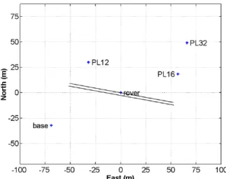
A test was conducted at the bridge. Three PLs (PL12, PL16 and PL32) were used in the trial, and their config- uration is illustrated in Fig. 1. The locations of the PLs were selected so that there was a clear line-of-sight to both the reference receiver antenna and the bridge antenna.
Additionally, their location was selected so as to be easily
surveyed by GPS. Practical locations of the PLs was limited
to the footpaths alongside the bridge, which were at neg-
ative elevation angles to the rover antenna. Also, the loca-
tion of one PL(PL12) meant that the line-of-sight signal to
Table 1 Pseudolite geometry with respect to base and rover.
Fig. 1 Location of GPS receivers and Pseudolites.
the base antenna passed through one of the bridge arches.
The elevation angles of the PLs from the base antenna were close to zero, and Table 1 lists the elevation and azimuth angles, and distance, of the PLs from both the base and rover antennas.
Two types of GPS receivers were used in the trial, and connected to the same antenna. The receivers were used to provide an independent check on the quality of the GPS data and their dual-frequency capability would enable ambi-
guities to be resolved kinematically On-The-Fly (OTF).
The PLs were assigned GPS PRN codes 12, 16 and 32, and operated in a pulsed mode with a 10% duty cycle. Their pow- er was adjusted to give good signal-to-noise ratios at both the base and rover, and not too strong so as to jam the GPS signals. All PLs used passive patch antennas, manufactured by Micropulse. During the test the receivers collected ap- proximately 50 minutes of data at a 1Hz sampling rate.
2.1 Geometry analysis of GPS and pseudolite augmented GPS
There were between 4 and 5 satellites available above 15 degrees during the trial, and Fig. 2 shows the elevation and sky-plot of the satellite and PLs with respect to the rover.
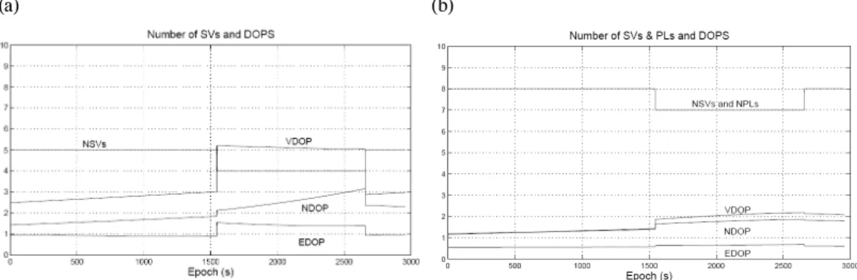
It is useful to investigate the geometry of the GPS satellites during the trial, and the improvement due to the PL augmen- tation at the rover antenna. Figs. 3a and b show the Dilution of Precision (DOP) in East, North and Vertical directions, together with the number of SVs/PLs available. From Fig.
3a it is clear that the drop in the number of GPS satellites
from 5 to 4 has a major impact on all the DOP values. The
mean DOP values indicate that the worst geometry is in the
Vertical component (3.7), then North (2.1), and best in East
(1.1). With the addition of the three PLs, the drop in number
(a) (b)
Fig. 3 Dilution of precision with respect to rover.
Table 2 Summary of DOP values GPS-only and GPS augmented with pseudolites.
of satellites from 5 t0 4 has less of an impact on the DOP values, as indicated in Fig. 3b, and the mean DOP values are all less than 1 (Table 2). The best geometry improve- ments are in the Vertical (58%) and East (46%), and the least improvement is in North (20%). Moreover, the average DOP in the Vertical. (1.5) is slightly better than in the North (1.7), When GPS is augmented with PLs.
2.2 Data Processing and pseudolite multipath error
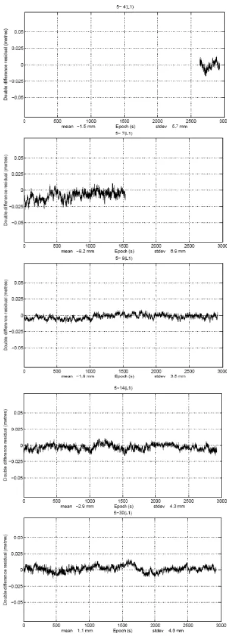
For all the data processing a satellite elevation mask of 15 degrees was used, and the final solution type was L1 dou- ble-difference ambiguity-fixed. For PLs used in a static en- vironment, over short distances, multipath is the dominant error and theoretically is a constant. Therefore, it is neces- sary to determine any multipath bases associated with the PL data before using them in position computations. In or- der to compute the multipath biases it was assumed that any small bridge movements would not significantly affect the PL multipath bias. Carrier phase double-differenced re-
siduals were computed for the GPS and PL data using SV as a reference satellite. Plots of double-differenced re- siduals for the satellites are as expected, with small mean values (less than 8.3 mm) indicating no significant biases.
There are visually some small time series fluctuations, which are possibly due to bridge movement and/or multipath. Fig. 4 shows that the PL double-difference re- siduals have significant constant biases, caused by the multipath. The mean values of the time series, in milli- meters, are 47.2 (PL12), 29.8 (PL16) and - 13.8 (PL32). The largest bias is for PL12, and could be due to the fact that the line-of-sight passes through one of the bridge arches.
2.3 Results of GPS-only positioning
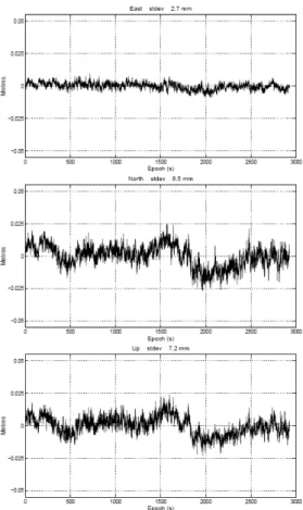
Figs. 6 and 7 show the GPS-only positioning results in
East, North and Vertical. It is clear that the fluctuations in
both are very similar, but there is less noise in the Allstar
solution. The standard deviations of the Allstar solution are
between 7 and 12% smaller than those of the Leica (Table
Fig. 4 PL DD residuals.
Fig. 5 GPS DD residuals.
3). This shows that the Allstar receiver can provide good quality L1 carrier phase data. From the position time series it is also clear that the precision in the Vertical and North are worse than the East, with standard deviations approx- imately two times larger. From the geometric analysis in section 2.1 this result is as expected. with best to worst pre- cision in the position components of East, North, Vertical.
2.4 Results of GPS-PL positioning
Fig. 8 shows the PL-augmented GPS solution position- ing results for East, North and Vertical from Allstar re- ceiver, and Table 4 gives the standard deviations of the posi- tion time series. The standard deviations in the East compo- nent are less than 3mm and smaller by 41% in comparison
in the Vertical component is better than the North. From the
geometric analysis in section 2.1 this result is as expected,
with best to worst precision in the position components of
Fig. 6 Leica SR GPS-only positioning result in East, North and Vertical.
Fig. 7 CMC AllstarGPS-onlypositioning result in East, North and Vertical.
Table 3 Standard deviations of East, North and Vertical time series for GPS-only and GPS-PL.
known (all PLs had similar SNR values).
2.5 Analysis of GPS-PL result
It is useful to consider the orientation of the bridge with respect to the position components. Fig. 1 shows that the length of the bridge runs approximately in an East-West direction. Therefore, movements in the East-West direc- tion are expected to be small, and this clearly is the case in the East time series plot (Fig. 8). On the other hand Vertical and North movements of the bridge are expected. However, some of the fluctuations in the North and Vertical time series are very similar and Vertical time series are very similar and of very low frequencies. Because of these two factors the
very low frequency fluctuations in the North and Vertical time series are unlikely to be actual bridge movement.
3. Conclusions
In this paper it has been demonstrated that when GPS is augmented with PLs similar positioning precision (sub-cm) can be obtained for both the horizontal and vertical components. Due to location of the pseudolites in the trial, the best improvements in precision were in the East and Vertical components by 41% and 31% respectively, and least in the North component (6%).
The pseudolite measurements had constant biases due to
multipath error, of which the largest was near 5cm.
Fig. 8 GPS-PL CMC Allstar positioning result in East, North and Vertical.
However the almost static nature of the trial allowed the multipath bias to be calibrated and removed from the pseu- dolite measurements.
the Multipath error from one of the satellites propagated into the North and Vertical positioning time series and con- taminated any detectable bridge movements. This satellite was critical to the North-South geometry and so could not be removed from the solution. There are several possible options by which satellite multipath could be reduced, and
Ltd. for their valuable comments and GPS equipments.
Also we extend our thanks to KOWACO for the help in the field work.
REFERENCES
Barnes, J., J. Wang, C. Rizos, T. Nunan, and C. Reid (2002a) The development of a GPS/Pseudolite positioning system for vehicle tracking at BHP Billiton steelworks.15th Int. Tech.
Meeting of the Satellite Division of the US Inst. of Navigation, 24-27 September, Portland, Oregan, 1779-1789.