소형 자동차의 머플러 형상에 따른 유동에 관한 융합 연구
최계광1, 조재웅2*
1공주대학교 금형설계공학과 교수, 2공주대학교 기계자동차공학부 교수
A Convergent Study on Flow According to the Configuration of Small Car Muffler
Kye-Kwang Choi1, Jae-Ung Cho2*
1Professor, Department of Metal Mold Design Engineering, Kongju national University
2Professor, Division of Mechanical & Automotive Engineering, Kongju National University
요 약 본 연구에서는 자동차 머플러의 형상별 유동해석을 수행하여 가장 유동성을 증가할 수 있는 설계 모델을 찾는 데에 있다. Model B가 최대 압력이 비교적 가장 작게 나오고 Model C가 가장 크게 나왔다. 자동차의 머플러 형상에 따른 최고의 유동 속도를 비교하면 Model A가 비교적 입구 및 출구에서의 유동의 흐름이 원활했다. 그러나 Model B는 머플러 내에서의 유동 속도는 크지만 출구에서는 유동 속도가 가장 적어져서 유동의 효율성은 떨어져 보인다. 머플 러의 형상에 따른 유동 해석 결과에 의하여 좀 더 유동이 원활한 모델을 찾음으로서 머플러를 효율적으로 설계할 수 있다고 사료된다. 본 연구 결과를 이용하면 실제 실험을 하지 않아도 소형 자동차의 머플러 형상에 따른 유동을 조사할 수 있다. 또한 소형 자동차의 머플러의 미적인 융합 설계에 도움이 될 수 있다고 보인다.
주제어 : 소형 자동차, 머플러, 유동, 유동 압력, 유동 속도, 융합
Abstract The flow analysis by each configuration of automotive muffler in this study was carried out.
And it aims at finding the design model that can increase the flow property best. It is shown that model B has the lowest maximum pressure and model C has the largest. Compared with the best flow rate according to the shape of the automotive muffler, model A had the comparatively smooth flow stream at the entrance and exit. However, model B has the largest flow rate in the muffler but the least flow rate in the exit, making it look less efficient. By the flow analysis result according to the muffler configuration, it is thought to design the muffler effectively by looking for the model with more smooth flow. The result of this study can be used to investigate the flow according to the configuration of small car muffler without actual test. It also seems to be helpful in the aesthetic convergent design of small car muffler.
Key Words : Small car muffler, Muffler, Flow, Flow pressure, Flow velocity, Convergence
*Corresponding Author : Jae-Ung Cho([email protected])
Received September 2, 2020 Revised October 5, 2020 Accepted January 20, 2021 Published January 28, 2021
1. 서론
전기 자동차, 수소 자동차 등 나날이 발전해 나가고 있 고 그만큼 수요도 증가하고 있다. 자동차가 증가함에 따 라 우리는 항상 환경문제나 소음문제가 같이 따라온다.
이렇게 증가하는 자동차 때문에 환경문제나 소음문제도 나날이 심각해지고 있다. 자동차의 증가함에 따라 환경문 제나 소음 문제가 심각해지고 있다. 아파트 옆에 도로가 늘어나고 그에 따라 소음이 증가한다. 소음 문제를 해결 할 수 있는 부품은 바로 머플러이다. 머플러는 자동차의
유동 해석 결과를 통하여 유동이 더 원활한 형상을 찾으 므로서 쉽게 머플러를 효율적으로 설계할 수 있다고 사 료된다[11-17]. 본 연구에서의 해석 결과를 활용하면 실 제로 소형 자동차의 머플러 형상에 따른 유동시험을 하 지 않고서도 그 유동을 조사할 수 있다고 보인다. 그리고 본 연구의 결과는 소형 자동차의 머플러의 미적 융합 설 계에 도움이 될 수 있다고 보인다[3-6].
2. 모델 및 유동 조건
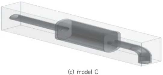
본 연구에서는 자동차의 머플러 형상에 따른 유동 해 석을 수행하기 위하여 해석 프로그램인 ANSYS를 이용 하였다. Fig. 1은 머플러의 형상에 따른 유동장을 나타낸 다. 유동장의 크기는 사각형 모델로서 가로, 세로 및 길이 가 60 mm, 200mm, 385mm로 하였다. 그리고 Fig. 2 는 대표적으로 유동 해석 조건을 나타낸다. 본 연구의 유 동 해석을 위한 조건으로는 입구부에 10m/s의 속도를 부여하였다. 출구부에는 1 atm의 압력 조건을 부여하였 다. 그 외의 모든 부분들에서는 No Slip Condition 조 건을 주었다. 또한 해석에 사용된 유체는 일반적인 기체 를 대표할 수 있는 25℃에서의 공기의 물성치를 사용하 였다.
(a) model A
(b) model B
Fig. 2. Condition of flow analysis
Table 1. Numbers of nodes and elements on flow models
Model Nodes Elements
Model A 7438 29616
Model B 8302 32624
Model C 8353 32434
Table 1은 유동 모델의 형상별 메시에 대한 절점수와 요소수들을 나타낸다.
3. 해석 결과
Fig. 3은 머플러의 다양한 면 분포에 대한 등고선들이 고 자동차 머플러에 따른 모델별, 유동 모델의 중간 부분 에서의 배면도에서의 압력 분포를 비교한 그림들이다.
Model A에서의 최대 압력은 136673 Pa로 유동이 처음 으로 통과하는 입구 부분에서 제일 크게 나온다. Model B는 최대 압력은 118783 Pa로 나온다. Model C는 최 대 압력이 173954 Pa이 나오는데 세 모델 유동이 통과 하는 머플러의 입구 부분에서 최대 압력이 측정된다. 유 동이 통과하는 부분에서 최고 압력이 제일 높은 모델은 Model C가 제일 높고 그 다음으로 Model A이고 Model B가 가장 낮게 나왔다.
(a) Model A
(b) Model B
(c) Model C
Fig. 3. Flow pressure contour on rear side by each model
Fig. 4는 유동 모델의 중간 부분에서의 배면도에서의 유동 속도의 분포를 비교한 그림들이다. Model A에서의 최고 속도는 274.662 m/s로 유동이 처음으로 통과하는 입구 부분에서 크게 나온다. Model B는 최고 속도는 278.449 m/s로 나오는데 입구 부분에서 가장 속도가 빠 르다. Model C는 최고 속도는 204.997 m/s가 나오는 데 들어오는 입구와 출구에서 나타난다. 유동이 통과하는 부분에서 최고 속도가 제일 높은 모델은 Model B가 제 일 높고 그 다음으로 Model A이고 Model C가 제일 속 도가 낮은 것으로 나왔다.
(a) Model A
(b) Model B
(c) Model C
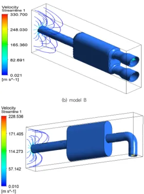
Fig. 4. Flow velocity contour on rear side by each model Fig. 5는 머플러 형상에 따른 유동 해석 비교로서 Model A, B 및 C에서 유동의 최대 속도는 322.373 m/s, 330.700 m/s 및 228.536 m/s로서 Model B가 유동의 흐름이 제일 빠르게 나타났다.
(a) model A
(b) model B
(c) model C
Fig. 5. Flow velocity contour by each model
(a) Model A
(b) Model B
(C) 출구
Fig. 6. Flow velocity on the section just before exit by each model
Fig. 6은 유동 모델의 오른쪽 바깥으로부터의 45mm 에 있는 출구 직전에서의 유동 속도에 대한 등고선을 표 시하고 있다. Model A가 그 최대 속도가 251.451 m/s 로 가장 크게 나왔고 Model C가 191.285 m/s로 그 다 음으로 크게 나왔고 Model B가 171.303 m/s로 나왔다.
Model A가 비교적 입구 및 출구에서의 유동의 흐름이 원활했지만 Model B는 머플러 내에서의 유동속도는 크 지만 출구에서는 유동 속도가 가장 적어져서 유동의 효 율성은 떨어져 보인다.
4. 결론
본 연구는 자동차 머플러의 형상별 유동해석을 수행하 여 가장 유동성을 높일 수 있는 설계 모델을 검토하였다.
이에 대한 연구결과는 아래와 같다.
1. 자동차 머플러가 받는 압력에 대한 결과를 확인하 였다. 세 모델 유동이 통과하는 머플러의 입구 부분 에서의 최대 압력을 보였다. Model B가 최대 압력 이 비교적 가장 작게 나오고 Model C가 가장 크게 나왔다.
2. 자동차 머플러 형상에 따른 최고 속도를 비교하였 다. Model A가 비교적 입구 및 출구에서의 유동의 흐름이 원활했지만, Model B는 머플러 내에서의 유동속도는 크지만 출구에서는 유동 속도가 가장 적어졌다. 유동의 효율성은 떨어져 보인다.
3. 머플러의 형상에 따른 유동 해석 결과를 통하여 좀 더 유동이 원활한 형상을 찾음으로서 머플러를 효 율적으로 설계할 수 있다고 사료된다. 그리고 본 연 구의 결과는 소형 자동차의 머플러의 미적 융합 설
계에 도움이 될 수 있다고 보인다.
REFERENCES
[1] J. U. Cho. (2015). Study on Convergence Technique through the Flow Analytical Study inside the Faucet for Bathroom. Journal of the Korea Convergence Society, 6(2), 37-42.
DOI : 10.15207/JKCS.2015.6.2.037
[2] S. H. Jo, J. I. Park & K. W. Nam. (2006). Numerical Simulation in the IC Engine Lubricating Gerotor Oil Pump. The Korean Society of Mechanical Engineers, 30(10), 1019-1025.
DOI : 10.3795/KSME-B.2006.30.10.1019
[3] J. H. Lee & J. U. Cho. (2015). Study on Convergence Technique through Flow Analysis at the Flexible Joint of the Pipe Laying. Journal of the Korea Convergence Society, 6(3), 13-18.
DOI : 10.15207/JKCS.2015.6.3.013
[4] H. C. Lee & J. U. Cho. (2014). A Study on Air Flow Analysis due to the Shape of Automotive Body. Journal of the Korea Convergence Society, 5(2), 19-23.
DOI : 10.15207/JKCS.2014.5.2.019
[5] S. C. Yoo. (2018). Development of the Design and Manufacturing Technologies of the Experimental Four-Valve SI Engine for In-Cylinder Air Flow Study Using the Laser Based Flow Diagnostic Techniques.
Journal of the Korean Society of Mechanical Technology, 20(3), 377-382.
DOI : 10.17958/ksmt.20.3.201806.377
[6] O. B. Suk & J. U. Cho. (2018). A Convergence Study through Flow Analysis due to the Configuration of Automotive Air Breather. Journal of the Korea Convergence Society, 9(10), 265-270.
Doi : 10.15207/JKCS.2018.9.10.265
[7] M. H. Chung, S. M. Yang & H. Y. Lee. (2005). 3D Flow Analysis of Globe Valve with Air Operated Actuator.
Korean Society for Fluid machinery, 8(4), 7-13.
DOI : 10.5293/KFMA.2005.8.4.007
[8] J. U. Cho. (2014). A Flow Analysis on Wing Shape of Cooling Fan at Automobile. Journal of the Korea Convergence Society, 5(4), 75-79.
DOI : 10.15207/jkcs.2014.5.4.075
[9] R. D. Gyeom & L. K. Bock. (2019). Flow Characteristics and Wind Loads on the Solar Panel and Floating System of Floating Solar Generato. Journal of the Korea Academia-Industrial cooperation Society, 20(10), 229-235.
DOI : 10.5762/KAIS.2019.20.10.229
[10] D. W. Jeong, Y. S. Won & S. H. Kang. (2019).
Comparison Study on Aerodynamic Performance and Wake Flow Field for a MW-Class Wind Turbine Model.
Journal of the Korean Society of Visualization, 17(2),
32-38.
DOI : 10.5407/jksv.2019.17.2.032
[11] S. W. Park, I. S. Choi, K. C. Noh, S. P. Ryu & K. S.
Yoon. (2012). An Experimental Study on Measurement of Flow Coefficient Using the Steady-Flow Test Rig.
Journal of the Korean Society of Marine Engineering, 36(4), 423-429.
DOI : 10.5916/jkosme.2012.36.4.423
[12] C. W. Kang, C. S. Yi & C. W. Lee. (2019). Experiment and Flow Analysis of the Flow Coefficient Cv of a 1 inch Ball Valve for a Thermal Power Plant. J ournal of the Korean Society of Manufacturing Process Engineers, 18(3), 109-115.
DOI : 10.14775/ksmpe.2019.18.3.109
[13] J. Y. Cho, S. H. Go & H. G. Kim. (2017). Analysis of Drainage Efficiency of Different Type of Drainage using Computational Fluid Dynamic Method. Journal of the Korean Society of Manufacturing Process Engineers, 16(2), 34-43.
DOI : 10.14775/ksmpe.2017.16.2.034
[14] H. K. Kim & H. M. Cho. (2014). A Study on Comparative Analysis of Internal ECV Through Flow Analysis. Journal of the Korean Society of Mechanical Technology, 16(1), 1161-1166.
DOI : 10.17958/ksmt.16.1.201402.1161
[15] P. G. Park, E. S. Lee, E. H. Jeong & J. H. Kim, (2007).
Numerical Flow Analysis of a Supersonic Impulse Turbine with Nozzles and Rotor Blades, Korean Society for Fluid machinery, 10(1), 26-33.
DOI : 10.5293/KFMA.2007.10.1.02
[16] J. H. Ku. (2017). A Study on the Platform for Big Data Analysis of Manufacturing Process. Journal of Convergence for Information Technology, 7(5) , 177-182.
[17] S. Y. Min & S. I. Kim. (2018). Study on Improvement of tap water drinking rate of Seoul city Tap water
‘Arisu’ through usage and recognition analysis. Journal of Digital Convergence, 16(9), 399-404.
최 계 광(Kye-Kwang Choi) [정회원]