• 검색 결과가 없습니다.

Thermal Characteristics of 20 W LED Module on Light Thermal Conductive Plastic Heat Sink: Comparison with that on Aluminum Die Casting Alloy (ADC-12)

N/A
N/A
Protected

Academic year: 2021

Share "Thermal Characteristics of 20 W LED Module on Light Thermal Conductive Plastic Heat Sink: Comparison with that on Aluminum Die Casting Alloy (ADC-12)"

Copied!
6
0
0

로드 중.... (전체 텍스트 보기)

전체 글

(1)

DOI: http://dx.doi.org/10.4313/JKEM.2016.29.6.380 ISSN 1226-7945 (Print), 2288-3258 (Online)

경량화 열전도성 플라스틱 Heat Sink기반 20 W급 LED Module의 열 특성: 다이캐스팅합금 (ADC-12)과 비교 연구

여정규1, 허인성2, 이승민3, 최희락4, 유영문2,a

1 부경대학교 LED공학협동과정

2 LED-해양융합기술연구센터

3 원광대학교 정보통신공학과

4 부경대학교 재료공학과

Thermal Characteristics of 20 W LED Module on Light Thermal Conductive Plastic Heat Sink: Comparison with that on Aluminum Die Casting Alloy (ADC-12)

Jung-Kyu Yeo

1

, In-Sung Her

2

, Seung-Min Lee

3

, Hee-Lack Choi

4

, and Young-Moon Yu

2,a

1 LED Engineering Interdisciplinary Program, Pukyong National University, Busan 48547, Korea

2 LED-Marine Convergence Technology R&D Center, Pukyong National University, Busan 48547, Korea

3 Department of Information & Communication Engineering, Wonkwang University, Iksan 54538, Korea

4 Materials Science and Engineering, Pukyong National University, Busan 48547, Korea

(Received January 13, 2016; Revised March 24, 2016; Accepted April 3, 2016)

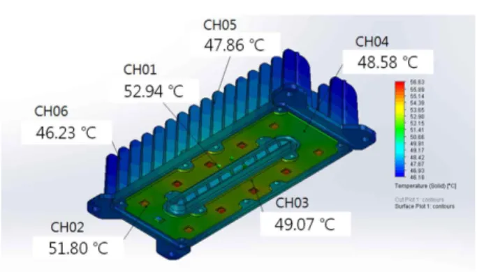
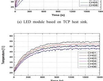
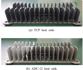
Abstract: Thermal characteristics of 20 W LED module on light thermal conductive plastic (TCP) heat sink were

investigated in comparison with that on aluminum die casting alloy (ADC-12). Thermal simulations of the heat sinks were conducted by using flow simulation of SolidWorks with the following input parameters: density is 1.70 and 2.82 kg/㎡, thermal conductivity is 20 and 92 W/(m·K) for TCP and ADC-12, respectively. The simulated and measured temperatures of the LED modules on TCP heat sink were consistent with its measured temperature, which was 3℃ higher that on ADC-12. The fabricated LED module on TCP heat sink with a weight of 120.5 g was 30% lighter in weight than that of the ADC-12 reference with 171.0 g.

Keywords: LED module, Thermal conductive plastic (TCP), Heat sink, Thermal simulation

1. 서 론

1)

세계적으로 환경보호 추세에 따라 조명 분야에서도 형광램프 및 백열전구보다 친환경 및 고효율적인 LED

a. Corresponding author; [email protected] Copyright ©2016 KIEEME. All rights reserved.

This is an Open-Access article distributed under the terms of the Creative Commons Attribution Non-Commercial License (http://creativecommons.org/licenses/by-nc/3.0) which permits unrestricted non-commercial use, distribution, and reproduction in any medium, provided the original work is properly cited.

(light emitting diode)를 사용한 조명 개발이 활발히 진

행 중이며 판매되고 있다. 하지만, LED는 반도체 소자의

단점 중에 하나인 열에 취약한 특성을 가지고 있기 때문

에 발생한 열을 효과적으로 전달해야 신뢰성을 확보할

수가 있다 [1]. LED 접합부에서 발생한 열을 외부로 전

달하는 방법으로는 열전도도가 높은 금속을 heat sink로

제작하여 부착하는 방법이 가장 대표적이다. 하지만, 금

속으로 heat sink를 제작하게 되면 연마 및 코팅 등의

후처리 공정이 필요하며, 공기 중에서의 부식발생과 조명

(2)

기기의 무게가 무거워지는 단점이 있다.

부식방지 및 경량화를 할 수 있는 열전도성 플라스틱 을 이용한 LED 조명 제품들이 다양하게 연구되어지고 있다. 자동차 LED 전조등 방열구조 연구 [2]와 5 W LED module 방열체에 대한 연구 [3], 엔지니어링 플라 스틱의 방열판 적용 [4]에 관한 연구 등이 진행되고 있으 며, 방열성능 향상에 대한 재료설계 연구 또한, LED의 방열에 관한 연구 [5], LED 광원의 효율 개선을 위한 방 열설계에 관한 연구 [6], 백색 LED 자동차 헤드램프의 방열설계 [7] 등 다양하게 진행되고 있다.

본 논문에서는 기존의 방열부품으로 사용 중인 알루 미늄, 구리 등의 금속재료들이 가지고 있는 문제점인 중량과 부식, 후처리 공정을 해결하고자 [8], thermal conductive plastic (TCP)을 적용하여 한국도로공사 LED 조명등기구 표준의 부속서 A [9]에 부합한 20 W급 LED module의 heat sink를 설계하고자 한다. 또한, SolidWorks의 flow simulation을 활용하여 열해석 시뮬 레이션을 진행하고, 시뮬레이션 결과를 토대로 제작된 20 W급 heat sink를 이용하여, TCP 재질과 ADC-12 합금 (aluminum die casting alloy)의 방열 성능을 비 교 분석하였다.

2. 실험 방법 2.1 Heat sink 설계

그림 1은 설계된 heat sink의 2D 도면을 나타내고 있 다. Heat sink의 크기는 가로 150 mm, 세로 65 mm, 높이 35 mm이며, heat sink의 fin count는 16개, fin thickness는 2 mm, base thickness는 3 mm로 설계 하였다.

Fig. 1. 2D drawing of heat sink.

2.2 열해석 시뮬레이션 조건

시뮬레이션 환경 조건은 0.6 ㎥의 임의의 공간에서 y 축의 반대 방향으로 9.81 m/s

의 중력 가속도를 설정하 고, 내부 대기 온도 25℃에서 시뮬레이션을 진행하였다.

그림 2는 20 W급 LED module의 3D 모델링을 도식 화한 것으로 해석 모델은 크게 4가지로 구분되며 LED package (PKG)의 재질은 사파이어, PCB의 재질은 Al 5052와 copper, heat sink는 TCP와 ADC-12 합금으로 설정하였다.

LED PKG와 PCB-Cu와의 접촉은 성분이 Sn-95%, Ag-35%인 solder를 이용하여 결합하였으며, heat sink 와 PCB-Al의 접촉은 두께 0.152 mm이며, 열저항이 0.00051℃·㎡/W인 thermal pad로 결합하였다. 열해석 시뮬레이션은 총 20 W의 소비 전력에 약 35%의 광파워 (optical power)를 제외한 13 W를 LED PKG에 인가하 여 진행하였다.

Fig. 2. 3D drawing of 20 W LED module.

본 논문에 사용된 TCP는 Celanese사 E3607 제품을 활용하였다. TCP의 base polymer는 polyamide (PA)이 다. PA 수지의 특성으로는 마찰계수가 적고, 내마모성이 좋으며, 인장강도 및 충격강도가 우수하다. 또한, 전기 절연성과 내열성이 우수하며, 내유성이 극히 좋은 것으로 알려져 있다.

표 1은 열해석 시뮬레이션에 적용한 각 부분의 재질에

대한 물성치를 나타내고 있다. Heat sink 재질로 사용된

TCP의 밀도는 1.56 kg/㎥이고, 비열은 1,100 J/(kg·K),

열전도도는 20 W/(m·K)이다. ADC-12 합금의 밀도는

2.82 kg/㎥이고, 비열은 963 J/(kg·K), 열전도도는 92

W/(m·K)이다 [10].

(3)

Table 1. Material properties used in thermal simulation.

Layer Material Density [kg/㎥]

Specific Heat [J/(kg·K)]

Conductivity [W/(m·K)]

Heat sink

TCP 1.56 1,100 20.0

ADC-12 2.82 963 92.0

PCB-Al Al-5052 2.68 921 140.0

PCB-Cu Copper 8.90 390 390.0

LED PKG Sapphire 3.98 761 23.1

2.3 20 W급 LED module의 온도측정

실제 제작된 20 W급 LED module의 온도 측정을 위 하여 접촉식온도계를 이용하여 총 6 point를 측정하였 다. 전면 PCB에 2 point와 후면 heat sink 부분에 4 point를 측정하였다.

그림 3은 6 point를 나타내고 있다.

Fig. 3. Temperature measurement point of the LED module.

2.4 LED PKG의 접합온도 측정

LED PKG의 접합온도 측정은 JEDEC51-1에 의거 T3Ster 장비를 활용하여 LED PKG에 감지전류 1 mA와

정격전류 700 mA를 인가하여 온도 변화량을 측정하였 다. 여기에 초기 외부온도 23℃를 더해주면 접합온도를 구할 수 있다.

2.5 Heat sink 염수부식 시험

TCP 재질과 ADC-12 합금 재질의 heat sink를 염수 에 대한 부식 발생을 알아보기 위해 상온의 바닷물에 3 일간 넣어두었다.

아래의 그림 4는 실제 실험 사진을 나타내고 있으며, 좌측이 TCP 재질이고 우측이 ADC-12 합금 재질의 heat sink를 나타내고 있다.

Fig. 4. Salt corrosion testing of heat sink.

3. 결과 및 고찰 3.1 Heat sink 설계

2가지 재질의 heat sink 부피는 63,480 ㎣으로 동 일하며, TCP 재질의 heat sink의 무게는 120.5 g, ADC-12 합금 heat sink의 무게는 171.0 g으로 확인 되었다. Heat sink를 TCP 재질로 제작을 할 경우 ADC-12 합금으로 제작할 때 보다 50.5 g, 약 30%의 무게 절감이 가능하다는 것을 확인하였다.

Table 2. Properties of heat sink.

Material Volume

[㎣]

Weight [g]

TCP 63,480 120.5

ADC-12 63,480 171.0

(4)

3.2 열해석 시뮬레이션

그림 5는 2가지 재질의 열해석 시뮬레이션을 나타내고 있다. (a)는 TCP 재질 heat sink일 때의 결과로 heat sink의 최소온도는 42.63℃이고, 최고온도는 52.60℃로 확인되었다. (b)는 ADC-12 합금 heat sink일 때의 결과 로 heat sink의 최소온도는 46.18℃이고, 최고온도는 49.13℃로 확인되었다.

(a) LED module based on TCP heat sink.

(b) LED module based on ADC-12 heat sink.

Fig. 5. Thermographic images of thermal simulations of LED modules based on (a) TCP and (b) ADC-12 heat sinks.

열해석 시뮬레이션 결과, TCP 재질 heat sink의 최소 온도와 최고온도의 차이는 9.97℃로 ADC-12 합금 heat sink의 온도 차이 2.95℃보다 약 7℃ 높은 특성을 확인 하였으며, 그 이유로는 TCP 재질이 ADC-12 합금보다 열전도도가 약 78% 정도가 낮으므로 LED PKG에서 발 생한 열이 heat sink의 fin 부분까지 열전도가 잘 일어 나지 않기 때문이다. 하지만, 한국도로공사 LED 조명등 기구 표준에서 제시한 LED 조명의 외부 온도기준이 8 5℃ 이하이므로 기준에 만족하는 것을 확인하였다.

표 3은 각 부분의 온도를 나타내고 있으며, TCP 재질 heat sink를 사용할 경우 ADC-12 합금 heat sink를 사 용할 때 보다 PCB-Al, PCB-Cu, LED PKG, 3 부분에서 의 온도가 약 3℃ 높은 것으로 확인되었다.

Table 3. Simulation results of LED modules based on TCP and ADC-12 heat sinks.

Layer

Minimum [℃]

Average [℃]

Maximum [℃]

TCP ADC-12 TCP ADC-12 TCP ADC-12

Heat sink 42.63 46.18 49.24 48.16 52.60 49.13 PCB-Al 53.46 49.52 55.05 52.07 56.54 53.26 PCB-Cu 53.67 50.59 55.07 52.09 56.77 53.48

LED

PKG 55.40 52.57 55.80 54.98 59.91 56.63

3.3 LED module 온도측정

그림 6의 (a)는 TCP 재질의 heat sink일 때, (b)는 ADC-12 합금의 heat sink일 때, 열해석 시뮬레이션을 통해 얻은 6 point의 온도를 나타내고 있다.

(a) LED module based on TCP heat sink.

(b) LED module based on ADC-12 heat sink.

Fig. 6. Thermographic images of 6 points thermal simulations

of LED modules based on (a) TCP and (b) ADC-12 heat

sinks.

(5)

(a) LED module based on TCP heat sink.

(b) LED module based on ADC-12 heat sink.

Fig. 7. Measured temperatures at 6 points of fabricated LED modules based on (a) TCP and (b) ADC-12 heat sinks.

Table 4. Temperatures at 6 points of the simulated and fabricated LED modules based on (a) TCP and (b) ADC-12 heat sinks. (Ts: simulated temperature, Tm: measured temperature)

No.

TCP-based ADC-12-based

Ts [℃]

Tm [℃]

Ts-Tm [℃]

Ts [℃]

Tm [℃]

Ts-Tm [℃]

CH01 57.05 56.70 0.35 52.94 54.50 1.56

CH02 55.29 55.50 0.21 51.80 52.80 1.00

CH03 52.27 54.90 2.63 49.07 50.60 1.53

CH04 51.49 51.10 0.39 48.58 50.70 2.12

CH05 47.21 46.90 0.31 47.86 50.70 2.84

CH06 42.81 43.30 0.49 46.23 48.20 1.97

그림 7은 실제 제작된 LED module의 온도 측정 결 과 이며, (a)는 TCP 재질의 heat sink, (b)는 ADC-12 합금의 heat sink일 때를 나타내고 있다. TCP 재질일 경우, 채널 3에서 열해석 시뮬레이션과 실제 온도측정 결과의 차이가 2.63℃로 가장 크게 차이 났으며, 채널 3 을 제외한 나머지 5곳의 온도 차이는 약 1℃ 이내인 것 으로 확인되었다. 각 포인트의 정확한 수치는 표 4를 통 해 확인할 수 있다.

ADC-12 합금일 경우, 채널 5에서 열해석 시뮬레이션 과 실제 온도측정 결과의 차이가 2.84℃로 가장 크게 차 이 났으며, 채널 5를 제외한 나머지 5곳의 온도 차이는 약 2℃ 내외인 것으로 확인할 수 있었다.

3.4 LED PKG의 접합온도 측정

그림 8은 LED PKG의 접합온도 측정에 사용된 20 W 급 module을 나타내고 있다.

(a) LED module based on TCP heat sink.

(b) LED module based on ADC-12 heat sink.

Fig. 8. Real pictures of fabricated LED modules based on (a) TCP and (b) ADC-12 heat sinks.

Fig. 9. Junction temperature of LED PKG.

(6)

T3ster로 측정된 LED PKG의 온도 변화량은 그림 9 를 통해 확인할 수 있으며, TCP 재질 heat sink를 부착 하였을 때 46.63℃로 측정되었고, ADC-12 합금 heat sink를 부착하였을 때 45.72℃로 측정되었다.

실제 TCP 재질 heat sink를 부착하였을 때 LED PKG의 접합온도는 초기 외부온도 23℃를 더한 69.63℃

이고, ADC-12 합금 heat sink를 부착하였을 때 LED PKG의 접합온도는 68.72℃인 것을 확인할 수 있었다.

TCP 재질 heat sink를 사용하면 0.91℃가 높으나, 접합 온도가 85℃ 이하로 LED PKG의 신뢰성에는 문제가 없 을 것으로 사료된다.

3.5 Heat sink 염수부식 시험

2개의 heat sink를 3일간 염수에 넣어둔 결과 TCP 재질은 부식이 발생하지 않았으며, ADC-12 합금 재질은 부식이 발생이 시작된 것을 확인할 수 있었다. 추후 KS C IEC 60068-2-11에 의거하여 정확한 염수 분무 시험 을 진행할 예정이다.

(a) TCP heat sink.

(b) ADC-12 heat sink.

Fig. 10. Salt corrosion test results of (a) TCP and (b) ADC-12 heat sinks.

4. 결 론

20 W급 LED module의 heat sink를 TCP 재질과 ADC-12 합금으로 제작하여 방열 성능을 비교해 본 결 과 다음과 같은 결론을 얻었다.

1) Heat sink를 TCP 재질로 제작할 경우 무게를 약

30% 경량화 할 수 있으며, 연마 및 코팅 등의 후처리 공정의 불필요와 부식방지의 장점이 있다.

2) 열해석 시뮬레이션 결과, TCP 재질의 heat sink와 ADC-12 합금 heat sink의 최고 온도 차이는 3.47℃ 차 이가 나는 것을 확인하였다.

3) 실제 온도측정 결과 TCP 재질이 ADC-12 합금보 다 열전도의 성능이 떨어져 외부온도가 높으나, 한국도로 공사 LED 조명등기구 표준에서 제시한 85℃ 이하이므로 heat sink 재료로 사용하기에 적합하다고 사료된다.

4) LED PKG의 접합온도는 TCP 재질 heat sink를 부 착하였을 때 69.63℃로 접합온도가 85℃ 이하로 LED PKG의 신뢰성에는 문제가 없을 것으로 사료된다.

본 연구를 통해 TCP 재질을 활용하여 20 W급 LED module의 heat sink에 적용하였으며, ADC-12 합금으 로 제작할 때 보다 무게 감량이 가능하다는 점과 후처리 공정이 필요 없을 것으로 사료된다.

감사의 글

이 논문은 부경대학교 자율 창의 학술 연구비(2015년) 에 의하여 연구되었음.

REFERENCES

[1] J. K. Yeo, I. S. Her, Y. M. Yu, S. I. Lee, and H. L.

Choi, J. Korean Inst. Electr. Electron. Mater. Eng., 27, 535 (2014).

[2] H. J. Kim, D. K. Lee, H. J. Park, H. S. Yang, P. S. Na and J. S. Kwak, J. Korean Inst. Electr. Electron. Mater.

Eng., 28, 544 (2015).

[3] J. W. Lee, Thesis, p. 3, Kongju National University, Gongju (2013).

[4] Y. T. Cho, Journal of the Korean Society of Manufacturing Process Engineers, 12, 61 (2013).

[DOI: http://dx.doi.org/10.14775/ksmpe.2013.12.6.052]

[5] H. H. Wu, K. H. Lin, and S. T. Li, J. Microelectron, 43, 280 (2012). [DOI: http://dx.doi.org/10.1016/j.mejo.2012.01.007]

[6] B. S. Seo, K. J. Lee, Y. S. Cho, and D. H. Park, J.

Korean Inst. Electr. Electron. Mater. Eng., 26, 158 (2013).

[7] J. Wang, Y. X. Cai, X. J. Zhao, and C. Zhang, J.

Microelectron, 45, 245 (2014).

[8] W. H. Choi, D. H. Choi, and D. H. Park, Jou. of Korean Soc. of Mechanical Technology, 17, 51 (2015).

[DOI: http://dx.doi.org/10.17958/ksmt.17.1.201502.51]

[9] Korea Expressway Corporation Standard, LED Luminaires, (2013).

[10] MatWeb, http://www.matweb.com/

수치

그림  1은  설계된  heat  sink의  2D  도면을  나타내고  있 다.  Heat  sink의  크기는  가로  150  mm,  세로  65  mm,  높이  35  mm이며,  heat  sink의  fin  count는  16개,  fin  thickness는  2  mm,  base  thickness는  3  mm로  설계 하였다.
Fig.  3.   Temperature  measurement  point  of  the  LED  module.
Fig.  6. Thermographic  images  of  6  points  thermal  simulations  of  LED  modules  based  on  (a)  TCP  and  (b)  ADC-12  heat  sinks.
Table  4.  Temperatures  at  6  points  of  the  simulated  and  fabricated  LED  modules  based  on  (a)  TCP  and  (b)  ADC-12  heat  sinks
+2

참조

관련 문서

1 John Owen, Justification by Faith Alone, in The Works of John Owen, ed. John Bolt, trans. Scott Clark, "Do This and Live: Christ's Active Obedience as the

As a result of the thermal conduction analysis, a cooling zone is formed on the surface of the welding metal along the arc by a cooling medium, compared

Also, the design of an optimal heat sink requires a complete knowledge of all heat transfer characteristics between the heat source and the ambient air

The second method is for compensation thermal expansion offering pre-load assembling that the temperature change by the repetitive movement and the friction

This study the changes in structure and mechanical characteristics by the analysis on mechanical characteristics of the welding part and the post weld

This is because that the thermal conductivity and solar weighted absorption fraction of MWCNT/Fe 3 O 4 hybrid nanofluid is lower than those of MWCNT

Three-Dimensional heat conduction analysis on dissimilar joint by TIG Assisted FSW (TAFSW) is carried out using an analytical model to determine the thermal histories

This study reports sensitivity enhancement method of a temperature sensor based on fiber Bragg grating (FBG) in combination with an auxiliary materials with a